
|
|
| Journal Home Page |
[This article first appeared in Spaceflight magazine, a publication of the British Interplanetary Society, in Vol. 16, No.10, October 1974 (pp. 378-382). It was prepared in response to a number of requests from members for data and information on the Apollo on-board computers and especially the Lunar Module programs, routines and descent-type logic. The subject is difficult to compress - a complete technical description of the computer subsystems would be rather large - and readers requiring more detailed information are invited to contact the author at spaceuk@netcomuk.co.uk.][For those who wish to read more about the application of computers to spaceflight, the NASA History site has Computers in Spaceflight: The NASA Experience by James E. Tomayko.]
[We would like to thank Phill for contributing this essay to the Apollo Flight Journal.]
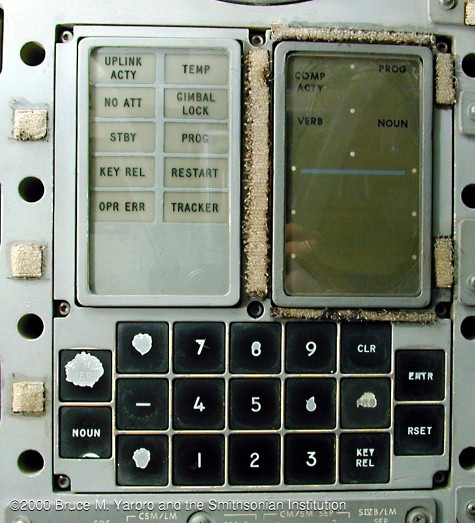
The Display & Keyboard (DSKY) mounted in the Main Display Console of the Apollo 13 spacecraft, Odyssey.
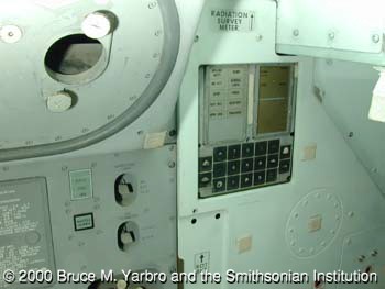
Odyssey's DSKY mounted in the Lower Equipment Bay next to the control panel for the spacecraft's optics.
The G&N system is semi-automatic, directed and operated by the three-man crew. It performs the basic functions of inertial guidance, attitude reference and optical navigation and is inter-related mechanically or electrically with the stabilisation and control, electrical power, environmental control, telecommunications and instrumentation systems. There are three main subsystems: inertial guidance, computer and optical. The inertial guidance subsystem senses acceleration changes and attitude changes instantaneously and provides attitude control and thrust control signals to the stabilisation and control system. Optical navigation subsystem sightings of celestial bodies and landmarks on the Moon and Earth are used by the computer subsystem to determine the spacecraft's position and velocity and to establish proper alignment of the stable platform.
The astronaut and computer communicate in a number language via the Display and Keyboard unit (pronounced 'disky' and abbreviated to DSKY), which has a 21-digit display and a 19-button keyboard. Two-digit numbers represent programmes, verbs and nouns. Five-digit numbers represent data such as position, velocity, etc. In the Apollo Command Module there is one computer and two DSKY's. The computer and one DSKY are located in the lower equipment bay and one DSKY on the main console. In the Apollo Lunar Module there is one main DSKY panel, the Primary G&N Panel, with a secondary Abort Guidance Panel at the LMP position. The Apollo Command Module G&N system and the Apollo Lunar Module G&N system are almost identical except that in the Lunar Module system the optical telescope is different and there is no sextant.
The computer is functionally divided into seven blocks: timer, sequence generator, central processor, memory, priority control, input-output and power. The timer generates the synchronisation pulses to assure a logical data flow from one area to another within the computer. Additionally, it generates timing waveforms used in alarm circuitry and other spacecraft areas for control and synchronisation. The sequence generator directs the execution of machine instructions by generating control pulses which sequence data throughout the computer. By combining the order code of an instruction word with synchronisation pulses from the timer, control pulses are formed. The sequence generator contains the order code processor, command generator and control pulse generator. The sequence generator executes the instructions stored in memory by producing control pulses, which regulate the data flow among various areas of the computer and elements of the central processor causing data to be processed according to the specification of each machine instruction.
The central processor performs all arithmetic operations required of the computer, buffers all data coming from and going to the memory, checks for correct parity of all words coming from memory and generates a parity bit for all words written into memory. It consists of flip-flop registers, the write, clear and control logic, write amplifiers, memory buffer register, memory address register and decoder and the parity logic. Primarily, the central processor performs operations indicated by the basic instructions of the programme stored in memory. Communication within the central processor is achieved through the write amplifiers. Data flows from memory to the flip-flop registers (or vice-versa), between individual flip-flop registers, or into the central processor from external sources. In all cases, data is placed on the 'write' lines and routed to a specific register or to another functional area under the control of the write, clear and read logic. The logic section accepts control pulses from the sequence generator and generates signals to read the content of a register onto the write lines and write this content into another register of the central processor or to another functional area of the computer. The particular memory location is specified by the content of the memory address register. The address is fed from the 'write' lines into this register, the output of which is decoded by the address decoder logic. Data is subsequently transferred from memory to the memory buffer register.
The memory buffer register buffers all information read out or written into memory. The flip-flop registers are used to accomplish the data manipulation and arithmetic operations. Each register is 16 bits (one computer word) in length. Control pulses, associated with each register, dictate data flows into and out of each register. These control pulses are generated by the write, clear and read control logic. External inputs through the 'write' amplifiers include the content of both the fixed and erasable memory bank registers, all interrupt addresses from priority control, control pulses associated with specific arithmetic operations and the start address for an initial start condition. Data from the input and output channels is placed on the 'write' lines and routed to specific destinations either within or external to the central processor.
Memory provides the storage for the computer and is divided into fixed memory and erasable memory. The fixed memory is high density core rope; tiny nickel-iron cores woven together with thousands of copper wires and encapsulated in plastic. Each core functions as a transformer and storage does not depend on magnetisation giving it the advantages of indestructibility, permanence of data and storage of vast data amounts in a small volume. The technique requires, however, that programmes for classes of various Apollo missions be developed and verified before the rope is woven, because the programme determines the weaving or wiring sequence. The erasable memory uses planes or ferrite (iron) cores as storage devices. A core is a magnetic storage device having two directions by passing a sufficient current through a wire piercing the core. The direction of the current determines the direction of magnetisation. The core retains this magnetisation until an opposite current switches the core in the opposite way. Wires carrying current through the same core are algebraically additive. Sense wires which pierce a switched core will carry an induced pulse.
Priority control establishes a processing priority of operations, resulting from conditions which occur both internally and externally, that must be performed by the computer. Priority control consists of counter priority control and interrupt priority control. Counter priority control initiates actions which update counters in the erasable memory. Interrupt priority control transfers control of the computer to one of many interrupt subroutines stored in the fixed memory. The Input-Output section routes and conditions signals between the computer and other areas of the spacecraft. The computer has a number of inputs besides counter and programme interrupt inputs. These are inputs from the spacecraft hardware or actions by the astronaut and enable the computer to be aware of conditions that exist in its 'environment', such as velocity change or angle changes. The outputs of the computer are data, control or condition indications. Some of these are controllable through the computer programme while others are present as a function of computer circuitry.
The Power section provides voltage levels necessary for the operation of the computer and is provided by two switching-regulator power supplies, a +4-volt and a +14-volt power supply, energised by the fuel cell power-plants in the electrical power subsystem.
| Number | Title |
|---|---|
| Service | |
| P00 | LGC Idling |
| P06 | PGNCS Power |
| P07 | Systems Test (Non-flight) |
| Ascent | |
| P12 | Powered Ascent Guidance |
| Coast | |
| P20 | Rendezvous Navigation |
| P21 | Ground Track Determination |
| P22 | RR Lunar Surface Navigation |
| P25 | Preferred Tracking Attitude |
| P27 | LGC Update |
| Pre-thrusting | |
| P30 | External delta-V |
| P32 | Co-elliptic Sequence Initiation (CSI) |
| P33 | Constant Delta Altitude (CDH) |
| P34 | Transfer Phase Initiation (TPI) |
| P35 | Transfer Phase Midcourse (TPM) |
| Thrust | |
| P40 | DPS Thrusting |
| P41 | RCS Thrusting |
| P42 | APS Thrusting |
| P47 | Thrust Monitor |
| Alignments | |
| P51 | IMU Orientation Determination |
| P52 | IMU Realign |
| P57 | Lunar Surface Alignment |
| Descent & Landing | |
| P63 | Landing Maneuvre Braking Phase |
| P64 | Landing Maneuvre Approach Phase |
| P66 | Rate of Descent Landing (ROD) |
| P68 | Landing Confirmation |
| Aborts & Backups | |
| P70 | DPS Abort |
| P71 | APS Abort |
| P72 | CSM Co-elliptic Sequence Initiation (CSI) Targeting |
| P73 | CSM Constant Delta Altitude (CDH) Targeting |
| P74 | CSM Transfer Phase Initiation (TPI) Targeting |
| P75 | CSM Transfer Phase Midcourse (TPM) Targeting |
| P76 | Target delta V. |
A generic LGC or CGC programme, such as LUMINARY I-D or COLOSSUS, is a functional grouping of major programmes (e.g. P30), routines (e.g. R30) and Service programmes (e.g. Interpreter). Table 1 lists the LGC programmes and major routines of the Apollo 14 mission as an example. The basic language of communication between the operator (astronaut) and the computer is a pair of words known as Verb and Noun. Each of these is represented by a two-digit decimal number. The verb code indicates what action is to be taken (operation) and the noun code what action is to be applied (operand). Typical verbs are those for displaying and loading while nouns usually refer to a group of erasable registers within the computer memory. Registers 1, 2 and 3 displays show the content of registers or memory locations and are read as decimal numbers, if a plus or minus sign is present, or as an octal number if no sign is used. Programme, verb and noun information is fed to the computer through the DSKY. The DSKY has ten numerical pushbutton keys (0 to 9), two sign keys (+ and -) and seven instruction keys (Verb, Noun, Clear, Proceed, Key Release, Enter and Reset). When a key is depressed, 14 volts are applied to a diode encoder to generate a unique 5-bit code for that key. There is, however, no 5-bit code for the Proceed key. Standard procedure for the execution of keyboard operations consists of a sequence of several key depressions. Normally, this is Verb, V1, V2, Noun, N1, N2, Enter. If the selected Verb-Noun combination requires data from the operator, the Verb and Noun lights flash on and off about once per second after the Enter key has been depressed. Table 2 lists, as an example, the Verb and Nouns available for the Apollo 14 Lunar Guidance Computer (LGC).
| Verb codes | |
|---|---|
| 05 | Display Octal Components 1, 2, 3 in R1, R2, R3. |
| 06 | Display Decimal (Rl or R1, R2 or R1, R2, R3) |
| 25 | Load Component 1, 2, 3 into R1, R2, R3. |
| 27 | Display Fixed Memory |
| 37 | Change Programme (Major Mode) |
| 47 | Initialise AGS (R47) |
| 48 | Request DAP Data Load Routine (RO3) |
| 49 | Request Crew Defined Maneuvre Routine (R62) |
| 50 | Please Perform |
| 54 | Mark X or Y reticle |
| 55 | Increment LGC Time (Decimal) |
| 57 | Permit Landing Radar Updates |
| 59 | Command LR to Position 2 |
| 60 | Display Vehicle Attitude Rates (FDAI) |
| 63 | Sample Radar Once per Second (R04) |
| 69 | Cause Restart |
| 71 | Universal Update, Block Address (P27) |
| 75 | Enable U, V Jets Firing During DPS Burns |
| 76 | Minimum Impulse Command Mode (DAP) |
| 77 | Rate Command and Attitude Hold Mode (DAP) |
| 82 | Request Orbit Parameter Display (R30) |
| 83 | Request Rendezvous Parameter Display (R31) |
| 97 | Perform Engine Fail Procedure (R40) |
| 99 | Please Enable Engine Ignition |
| Noun Codes | |
|---|---|
| 11 | TIG of CSI |
| 13 | TIG of CDH |
| 16 | Time of Event |
| 18 | Auto Maneuvre to FDAI Ball Angles |
| 24 | Delta Time for LGC Clock |
| 32 | Time from Perigee |
| 33 | Time of Ignition |
| 34 | Time of Event |
| 35 | Time from Event |
| 36 | Time of LGC Clock |
| 37 | Time of Ignition of TPI |
| 40 | (a) Time from Ignition/Cutoff (b) VG (c) Delta V (Accumulated) |
| 41 | Target Azimuth and Target Elevation |
| 42 | (a) Apogee Altitude (b) Perigee Altitude (c) Delta V (Required) |
| 43 | (a) Latitude (+North) (b) Longitude (+East) (c) Altitude |
| 44 | (a) Apogee Altitude (b) Perigee Altitude (c) TFF |
| 45 | (a) Marks (b) TFI of Next/Last Burn (c) MGA |
| 54 | (a) Range (b) Range Rate (c) Theta |
| 61 | (a) TGO in Braking Phase (b) TFI (c) Cross Range Distance |
| 65 | Sampled LGC Time |
| 66 | LR Slant Range and LR Position |
| 68 | (a) Slant Range to Landing Site (b) TGO in Braking Phase (c) LR Altitude-computed altitude |
| 69 | Landing Site Correction, Z, Y and X |
| 76 | (a) Desired Horizontal Velocity (b) Desired Radial Velocity (c) Cross-Range Distance |
| 89 | (a) Landmark Latitude (+N) (b)Longitude/2 (+E) (c)Altitude |
| 92 | (a) Desired Thrust Percentage of DPS (b) Altitude Rate (c) Computed Altitude |
 The current LM position and velocity vectors were determined from the navigation routine. The target position vector, velocity vector, acceleration vector and down-range component of Jerk (time derivative of acceleration) were obtained from the stored memory. The down-range components of these state vectors (current and desired) are used in the Jerk equation to determine the time-to-go (TGO) from the current to the desired conditions. If the TGO, current state vector and desired state vector are known, then the commanded acceleration vector can be determined from the quadratic guidance law. By using spacecraft mass, calculating the vector difference between commanded acceleration and the acceleration of lunar gravity, applying Newton's Law, then a commanded thrust vector can be found, the magnitude of which was used to provide throttling of the LM Descent Propulsion System (DPS). The vector direction was used by the LM Digital Autopilot (DAP) to orientate the DPS thrust by either trim gimbal attitude commands or RCS commands to re-orient the entire spacecraft.
The first programme used during the Apollo LM descent to the lunar surface was P63, which contained an ignition algorithm and the basic guidance logic. Based upon a stored, preselected target site surface range, the ignition logic determined the time for the crew to ignite the DPS for PDI (Powered Descent Initiate). After DPS ignition, the basic guidance logic was used to steer the LM to the conditions for the beginning of the Approach Phase (See Fig. 3).
When the Braking Phase Guidance programme, P63, reaches the preselected values, the guidance programme switches automatically to programme P64 (Approach Phase Guidance). This is basically the same as P63 but with a new set of targets but, in addition, provided window-pointing logic for the Landing Point Designator (LPD) operation. The LPD was a scale etched onto the LM forward triangular window, on the Commanders side, which the Commander could sight along to view the landing area to which the Apollo LM was being guided. The computer calculated the look-angle (relative to the forward LM body axis, ZB) and displayed it on the DSKY to assist the Commander in his LPD operation. The guidance programme switched automatically from programme P64 to programme P65 (Velocity Nulling Guidance) when the TGO reached a preselected value (See Fig. 4).
The P65 programme was used for an automatic vertical descent to the surface of the Moon by nulling all components of velocity to preselected values, if this was required. There was no position control during this programme. At any time during the operation of automatic guidance modes (P63, P64 or P65) the crew could call-up optional programmes P66 (Rate of Descent) or P67 (Manual Guidance) through the DSKY. During the P66 operation, the crew could control spacecraft attitude with the computer commanding the DPS throttle to maintain the desired altitude rate. This would normally have occurred near the end of the P64 programme, near low gate, prior to switching to P65 programme for manual control of the final touchdown position. Programme P67 maintained navigation and display operations for complete manual control of the throttle and altitude. This was not a 'normal' mode unless the programme, P66, was inoperative.
| Pre-launch & Service | |
|---|---|
| P00 | CMC Idling |
| P01 | Pre-launch or service initialisation |
| P02 | Pre-launch or service - gyro compassing |
| P03 | Pre-launch or service - optical verification of gyro compassing |
| P06 | GNCS Power down |
| PO7 | Systems Test |
| Boost/Coast | |
| P11 | Earth orbit insertion monitor (EOI) |
| P20 | Universal tracking |
| P21 | Ground track determination |
| P25 | Contingency VHF Range-Rate |
| P27 | CMC Update |
| P29 | Time-to-longitude |
| Pre-thrust Targeting | |
| P30 | External delta-V |
| P31 | First phasing maneuvre (NC1) |
| P32 | Second phasing maneuvre (NC2) |
| P33 | Corrective combination maneuvre (NCC) |
| P34 | Co-elliptic maneuvre(NSR) |
| P35 | Transfer Phase Initiation (TPI) |
| P36 | Transfer Phase Midcourse (TPM) |
| P37 | Rendezvous Final Phase |
| P38 | Plane Change (PC) |
| Thrusting | |
| P40 | SPS |
| P41 | RCS |
| P47 | Thrust Monitor |
| P48 | Rendezvous thrust monitor |
| Alignment | |
| P50 | ATM Orientation determination |
| P51 | IMU Orientation determination |
| P52 | IMU Realign |
| P53 | Back-up IMU orientation determination |
| P54 | Back-up IMU realign |
| P55 | ATM star tracker gimbal angles |
| Entry | |
| P61 | Entry preparation |
| P62 | Entry CM/SM separation and pre-entry maneuvre |
| P63 | Entry initialisation |
| P64 | Entry-Post 0.05g |
| P65 | Entry-Up control |
| P66 | Entry-ballistics |
| P67 | Entry-Final phase |
| Post Thrusting | |
| P77 | CSM Velocity vector updating |
|
|
| Journal Home Page |