Perspective
Since 1960, the NASA Manned Space Flight Program has successfully accomplished 55 manned flight missions. This outstanding record has been based for the most part on the building of a competent technical and management organization within NASA and the aerospace community. The systems management approach, which was exercised to its fullest during the Apollo program, has been the basis for all subsequent manned programs - Skylab, Apollo-Soyuz, and now Shuttle. The completeness of the identification of requirements to the thoroughness of critical design and certification reviews to obtain maximum assurance that the Shuttle flight hardware is acceptable to fly is essentially the same as the system implemented on the previous manned programs.
It is the considered opinion of the Production and Development Team that there have been many outstanding achievements in the Space Shuttle development, and even though the cause of the 51-L accident appears to be isolated to one element of the system, the possibility exists that if the accident is directly or indirectly related to a Development and Production deficiency, then a similar deficiency could exist in other elements of the program. Consequently, the report highlights potential areas of concern without corresponding treatment of the program approaches and activities that are exemplary.
Introduction
In response to the STS 51-L accident on January 28, 1986, an interim mishap Investigation Board was established by the Acting Administrator of NASA to initiate an investigation into the cause of the Shuttle Challenger accident. On March 11, 1986, the Acting NASA Administrator created the STS 51-L Data and Design Analysis Task Force to replace the interim mishap Investigation Board and to support the activities of the Presidential Commission on the Space Shuttle Challenger Accident. Rear Admiral Richard Truly was designated as Chairman of the 51-L DDATF who in turn organized the task force with four principal teams to be coincident with and responsible to the four previously identified Commission panels for: (a) Development and Production, (b) Prelaunch Activities, (c) Mission Planning and Operation, and (d) Accident Analysis.
This report pertains to the Shuttle program review activities ,of the Development and Production Team. The Development and Production Team was chartered to undertake a critical review and analysis of the design, development, test and evaluation of the NSTS hardware and systems involved in the STS 51-L accident, in order to ascertain the adequacy of these program activities.
With the exception of an initial meeting of the Commission's Development and Production Panel held at JSC on March 5, 1986, the NASA team in conjunction with the Commission panel conducted all reviews jointly as a group. These reviews consisted of contractor visits to Morton Thiokol, Incorporated, Wasatch, Utah; Rocketdyne, Canoga Park, California; Rockwell International, Downey, California; Martin Marietta, Michoud Aerospace, Michoud, Louisiana; and United Space Boosters, Incorporated, Huntsville, Alabama.
The Development and Production (D&P) Team, in conjunction with representatives of the Presidential Commission Development and Production Panel, conducted a series of reviews at the prime contractor facilities at the Johnson Space Center (JSC) and the Marshall Space Flight Center (MSFC) for the purpose of assessing the hardware acquisition program.
The four key areas investigated by the Development and Production Team/Panel were common to all the National Space Transportation System (NSTS) elements. They were: (a) the design of the element including design requirements, control and certification; (b) the development of the hardware: (c) the testing and qualification of the hardware; and (d) the evaluation of the results of the production of the product to meet the stringent requirements of the Space Shuttle Program. In all of the four areas, there was a consistency in the formality and rigor of how the elements were to proceed through these stages. The various Panels, Boards, and the logical progression of the extremely detailed major reviews all functioned essentially the same across the program.
A systematic review approach was utilized to assure continuity of the reviews, and a common agenda was followed by all parties. Special emphasis was placed on the design and qualification of the critical elements of the Space Shuttle launch vehicle and the evolution of the margins of safety of the critical structures.
The Commission Panel received an extremely comprehensive reviews, in the conduct of its duties and has full confidence that with the detailed reevaluation of the safety related critical items and the improvements or correction of any deficiencies, the Space Shuttle Program will be able to safely conduct its missions. The NASA development and production process is sound and the expansion of the operating margins will allow future safe space missions.
Each contractor addressed his procedures and approaches used to develop the Failure Modes and Effects Analysis (FMEA), the Critical Items List (CIL), and Hazards Analysis (HA).
Requirements for these products emanated from NASA Handbook (NHB) 5300.4. The purpose of the FMEA is to identify the various potential failure modes of the flight elements' components and assess the associated effects on the specific flight element as well as the total launch vehicle and mission. The potential failure modes are derived from analyses of function, design, and related manufacturing processes. The CIL identifies the critical failure mode; and the rationale for retention. The items contained in the CIL are classified in five major categories commensurate with the degree of criticality. The Hazard Analysis identifies the hazards and their status of resolution and categorizes them as controlled (by design, procedure, etc.) or as accepted risk.
It was the consensus of the Commission Panel that a reassessment of the FMEA/CIL, in conjunction with the hazard analyses, should be conducted to assure that Criticality 1 and 2 items are re-evaluated and that the hazard analyses properly identify the Criticality 1 items. Thus, the associated risks and hazards will be thoroughly understood and appropriate action can be taken to minimize their criticality. This effort should identify the major items which can be prioritized and receive the necessary management attention.
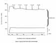
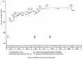
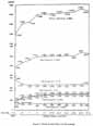
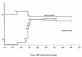
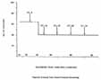
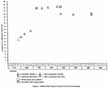
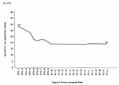
Figures 1 through 8 depict the history, by flight element, of the total number of critical items and hazards.
A fundamental finding by the Commission/Panel was that the NASA system and the working relationships with their respective element contractors were outstanding for the SSME, SRB, ET and Orbiter. MSFC/Rocketdyne (SSME), MSFC/Martin Marietta Michoud Aerospace (ET), MSFC/USB1 (SRB), and JSC Rockwell International (Orbiter) all had exceptional working relationships which anticipated and solved problems together and functioned very smoothly within the rigors of the design, development, test and evaluation of the hardware elements. These relationships have continued into the operational phase of the Shuttle program. The flow of technical data and potential problems has not been as timely or comprehensive with MSFC/MTI as with the other elements, and as a result, there have been gaps in the understanding of exactly how the SRM performed.
The investigation revealed that the contractual specifications imposed upon the Solid Rocket Motor (SRM) contractor clearly specified the natural and induced environmental requirements. These requirements were not met. Specifically, the design requirement for the motor to operate over a propellant mean bulk temperature of 40 to 90 degrees Fahrenheit was the only thermal requirement considered. Consequently, the as-built hardware was not verified to the intended natural and induced environments. Of particular interest were the field joints. Since they were not tested to the complete set of environmental requirements, a total understanding of the joint design limits was not obtained. This was further complicated because of insufficient development testing and analyses concerning the operational characteristics of the joint putty, joint rotation, and O-ring compression and resiliency.
The configuration of the SRM qualification test article did not totally represent that of the flight hardware. For example, preparation of the joint putty was not accomplished comparably on the qualification motor and the flight motor. The putty performance is a possible cause of the 51-L accident.
Prior to the STS 51-L accident, there was insufficient knowledge on the part of MTI and NASA relative to the performance characteristics of the putty used in the SRM field joint. It was originally thought that the putty would allow the SRM hot gas to pressurize the primary O-ring during the motor ignition transient. It has been subsequently learned that humidity and temperature enhance the putty characteristics relative to its pressure holding characteristics thereby delaying the proper actuation of the primary O-ring. The uncertainty of these characteristic changes directly effects the ability of the field joint to seal.
The adequacy of the SRM joint O-ring process and quality control was found to be questionable. The O-ring is allowed to include five scarf joints, a quantity which was arbitrarily established, and repairs of inclusions and voids are routinely made by the vendor after his receipt of the material supplies. Due to the criticality of this hardware in the operation of the SRM, it appears that more stringent control is necessary.
Mandatory inspection points were temporarily omitted from the O-ring acceptance criteria at MTI, and the secondary O-ring for the suspect 51-L field joint was processed when the mandatory inspection points were not in effect. The possibility exists that other areas similar in criticality may be suspect if a complete assessment of all mandatory inspections is not performed.
The SRM's were static tested in the horizontal position rather than in the flight attitude. A review of the considerations for this decision reveals the decision to be based mostly on programmatic considerations and the concern of determining the thrust values more accurately. It was not obvious that the effects of this deviation in test and flight configuration received sufficient attention.
It has been determined by measurement of two flown case segments that both the SRM tang and clevis sealing surfaces have increased in diameter beyond the anticipated design limits. The growth is believed to be material related and related to the hydrostatic proof test pressure level. This uncertainty must be resolved prior to any planned reuse of case segments.
Difficulty has been experienced with the SRM segments during mating operations at the launch site. The loaded segments are transported by railcar in the horizontal position. This shipment orientation could cause the cases to assume undesirable out-of-round conditions and contribute to the mating operations difficulty.
The Space Shuttle Main Engine (SSME) is recognized as a high technology, high power density, state-of-the-art rocket engine. It contains many high energy sources and therefore is a very complex and high risk element of the Space Shuttle system.
[K9] NASA and the contractor, both of which have experience in high technical liquid propulsion capabilities, have a thorough knowledge of the technical requirements for the development and operation of the engine. These capabilities allow technical penetration by the personnel such that potential problems are recognized in a timely manner and necessary resolutions are implemented. The mutual understanding of the complexity of the system and the attention of detail given has no doubt been an important factor in the success of the program to date.
The current SSME design is certified for 15 missions. Future operational requirements indicate a need for a continuous hot fire and off-nominal test program with multiple engines to demonstrate time far in excess of the Orbiter fleet leader. Such testing will demonstrate the full margin extent of critical components and subsystems.
The Orbiter development and production has been accomplished with thorough rigor and formality. However, there are several improvements now in process, as well as other potential improvements previously considered which should be re-reviewed and prioritized to assure minimization of hazards.
During the review process, the subject of the contractual separation of the launch site processing and inspection activities from the design organizations was addressed. Concern was expressed that the processing personnel may not possess the necessary technical background gained during the design and development phase to adequately determine system degradation resulting from multiple missions. The processing contractor also may not appreciate or recognize the criticality of the hardware being tested and processed.
Some of the manifested payloads require Orbiter modifications. Extremely complex and critical payloads such as Centaur should receive special safety emphasis reviews.
It was concluded that the development and certification of the non-SRM portions of the SRB have followed the NASA requirements and approved plans. The hardware design is mature. In order to assure continued success, attention must continue to be given to the details associated with the reacceptance of the reused hardware.
The Commission Panel suggested that additional instrumentation be incorporated on the SRB, prior to resumption of flights, to measure the SRM case joint parameters and SRB bending.
The ET contractor demonstrated that his technical and management staff are well versed in their respective areas of responsibilities and that the program is controlled and implemented by a disciplined system.
The lightweight External Tank configuration design incorporated a factor of safety of 1.25 for those loads that are well defined. A proration of the 1.25 factor and the more conservative 1.4 factor was used in other areas. This approach produced a lightweight design with sufficient margins of safety that resulted in more payload capability for the Space Shuttle Program.
The External Tank design incorporates a vent and relief valve on the L02 and LH2 tanks. The position indicator switch tolerances allow the valve to indicate being in the closed position when it may in fact be open up to 0.30 inch. Additional analyses and/or testing should be conducted to determine if this situation is a safety issue, followed by the necessary appropriate action.
II. Directive Appointing Development and Production Team/Charter
The 51-L Data and Design Analysis Task Force (DDATF) was established March 7, 1986, by Rear Admiral Richard H Truly, Associate Administrator for Space Flight, National Aeronautics and Space Administration (NASA). A detailed charter defining the DDATF organization, duties, responsibilities, and authority was published. As an attachment thereto, the General Assignment for Project Analysis Team document was issued which defined organization and responsibilities for the Project Analysis Team. Appendix A contains the aforementioned documentation.
Subsequent to the formation of the Project Analysis Team, its title was revised to the Development and Production Team to be consistent with the nomenclature of the Presidential Commission Panel of the same title.
III. Organization/Method of Investigation
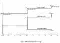
A. Organization
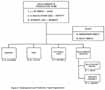
The organization of the Development and Production Team is depicted in Figure 9. The Team is comprised of a core membership which consists of Mr. Thomas J. Lee, MSFC/DDOI, Lead; Mr. C. E. McCullough, JSC/VP, Deputy Lead; Mr. Robert Stewart, JSC/CB, member; and Ms. S. G. Henderson, NISFC/SA76, and Mr. D. L. Riley, MSFC/SA71, staff. The remaining membership consists of a senior representative from each of the flight element project offices; i.e., Orbiter Project, External Tank (ET) Project, Solid Rocket Booster/Solid Rocket Motor (SRB/SRM) Project, and the Space Shuttle Main Engine (SSME) Project.
B. Method of Investigation
The D&P Team conducted a critical review and analysis of the acquisition phase of the STS 51-L flight hardware. This effort was accomplished in conjunction with representatives of the Presidential Commission Development and Production Panel who jointly received formal presentations by the respective project offices and their contractors. These presentations addressed the key elements of the hardware acquisition process and the modes of operation, management, and systems utilized by the various parties to satisfactorily convert the performance and design requirements into flight hardware which was properly manufactured, tested, and certified. The presentations included the results of engineering analyses and development and qualification testing.
An in-depth penetration of the various management and functional disciplines and processes was conducted with interest in the following:
- a. Design of critical elements
- b. Trade-offs in design versus cost, safety, schedule
- c. Test and evaluation of components, subsystems, and systems
- d. Quality and certification of components, subsystems, and system
- e. Engineering changes and waivers
- f. Process control
- g. Production capability
- h. Quality control
- i. Configuration control
- j. Refurbishment, processing, impacts, and difficulties
- k. Logistics support
- 1. Production deficiencies, development, and waivers
- m. Production testing
- n. Government acceptance process
- o. Shipping and handling
Tours of the manufacturing and checkout operations were conducted to further familiarize the team and panel membership with the flight hardware in review.
Question and answer sessions were conducted which involved the Team and Panel personnel and the project and contractor personnel, including subcontractor personnel.
As required, formal action items were assigned and tracked through completion in order to assure that the Team and Commission Panel members were provided the required information and data to conduct their investigation.
IV. Definitions of Terms and Acronyms
|
Acronyms |
Terms |
|---|---|
|
. | |
|
ADP |
Acceptance Data Package |
|
AFQA |
Air Force Quality Assurance |
|
[K11] AR |
Acceptance Review |
|
ASAP |
Aerospace Space Advisory Panel |
|
CAR |
Configuration Acceptance Review |
|
CCB |
Configuration Control Board |
|
CCV |
Coolant Control Valve |
|
CDF |
Confined Detonation Fuse |
|
CDR |
Critical Design Review |
|
CEI |
Contract End Item |
|
CIL |
Critical Items List |
|
COQ |
Certificate of Qualification |
|
D&P |
Development and Production |
|
DAR |
Deviation Approval Request |
|
DAS |
Document Accountability System |
|
DCN |
Document Change Notice |
|
DCR |
Design certification Review |
|
DDATF |
Data and Analysis Design Task Force |
|
DDT&E |
Design, Development, Test and Evaluation |
|
DM |
Development Motor |
|
DVS |
Design Verification Specification |
|
E&I |
Electrical and Instrumentation |
|
EAFB |
Edwards Air Force Base |
|
ECP |
Engineering Change Proposal |
|
EIS |
End Item Specification |
|
EMC |
Electromagnetic Compatibility |
|
EMI |
Electromagnetic Interference |
|
ET |
External Tank |
|
FASCOS |
Flight Acceleration Safety Cutoff System |
|
FM |
Frequency Modulation |
|
FMEA |
Failure Modes and Effects Analysis |
|
FMOF |
First Manned Orbital Flight |
|
FPL |
Full Power Level |
|
FRR |
Flight Readiness Review |
|
FWC |
Filament Wound Case |
|
GFP |
Government Furnished Property |
|
GSE |
Ground Support Equipment |
|
HCS |
Hardware Certification Sheet |
|
HOSC |
Huntsville Operations Support Center |
|
HPFTP |
High Pressure Fuel Turbopump |
|
HMP |
High Performance Motor |
|
HPOTP |
High Pressure Oxidizer Turbopump |
|
ICD |
Interface Control Document |
|
JSC |
Johnson Space Center |
|
KSC |
Kennedy Space Center |
|
LCC |
Launch Commit Criteria |
|
LH2 |
Liquid Hydrogen |
|
LO2 |
Liquid Oxygen |
|
LPPTP |
Low Pressure Fuel Turbopump |
|
LPOTP |
Low Pressure Oxidizer Turbopump |
|
LSC |
Linear Shaped Charge |
|
LSS |
Launch Support Services |
|
LWT |
Lightweight Tank |
|
MAF |
Michoud Assembly Facility |
|
MCC |
Main Combustion Chamber |
|
MCF |
Major Component Failure |
|
MMI |
MSFC Management Instruction |
|
MOR |
Manufacturing Operation Record |
|
MPP |
Manufacturing Process Plans |
|
MPTA |
Main Propulsion Test Article |
|
MRB |
Material Review Board |
|
MTI |
Morton Thiokol, Incorporated |
|
NASA |
National Aeronautics and Space Administration |
|
NHB |
NASA Handbook |
|
NSTL |
National Space Technology Laboratories |
|
NSTS |
National Space Transportation System |
|
OFI |
Operational Flight Instrumentation |
|
OMI |
Operations and Maintenance Instruction |
|
OMRSD |
Operations and Maintenance Requirements and Specification Document |
|
PDR |
Preliminary Design Review |
|
PMBT |
Propellant Mean Bulk Temperature |
|
PRCB |
Program Requirements Control Board |
|
PRR |
Program Requirements Review |
|
PSI |
Pounds Per Square Inch |
|
PSIG |
Pounds Per Square Inch Gage |
|
QM |
Qualification Motor |
|
SSME |
Space Shuttle Main Engine |
|
STA |
Structural Test Article |
|
STM |
Standard Materials |
|
STP |
Standard Processes |
|
SWT |
Standard Weight Tank |
|
TPS |
Thermal Protection System |
|
TVC |
Thrust Vector Control |
|
UCR |
Unsatisfactory Condition Report |
|
USBI |
United Space Booster Incorporated |
|
VAFB |
Vandenberg Air Force Base |
|
VCR |
Vehicle Configuration Review |
|
VLS |
Vandenberg Launch Site |
V. Technical Description and Analysis
As stated in III.B, Method of Investigation, the investigation conducted by the D&P Team was accomplished by a series of in-depth reviews of formal presentations given by the NASA project offices and their respective prime contractors.
A summary report on each of these investigations is provided in the following subsections which address each element, i.e., SRM, SRB, ET, SSME, and Orbiter.
To provide continuity of the investigation, the reviews conducted at the major elements' facilities all followed the same basic agenda:
- a. Design Requirements and Control
- b. Design Reviews and Certification System
- c. Verification Requirements, Planning, Documentation, and Control
- d. Development and Qualification
- e. Transportation and Handling Verification
- f. Design and Production Control
- (1) Configuration Control
- (2) Operating Plan and Control
- (3) Quality Control
- g. Launch Support Services
- h. Failure Mode Effects Analysis/Critical Items List (FMEA/CIL) Summary
- i. Response to Specific Previously Submitted Questions
- j. In-plant Review of Production
A. SRM Analysis
The D&P Team, in conjunction with representatives of the Presidential Commission, convened at Morton Thiokol, Incorporated (MTI), Wasatch Operations, Utah, on March 17 and 18, 1986, for the purpose of evaluating the SRM acquisition program. A series of formal presentations was provided by representatives of MTI. Mr. Sutter, Dr. Walker, and Mr. Rummel were the Presidential Commission members in attendance.
Appendix B, Space Shuttle Solid Rocket Booster Fact Book, SA44-80-02, provides a general description of the SRM.
The presentations, Appendix C hereto, addressed requirements and certification control, design reviews, requirements verification, [K12] design and production control, and transportation and handling. The contractor also provided a Failure Modes and Effects Analysis/Critical Items List summary presentation and provided answers to specific inquiries identified prior to the meeting by the Presidential Commission's Development and Production Panel.
A.1. Requirements and Control
Performance and design requirements for the SRM emanate from a variety of sources. These requirement sources are: (a) systems requirements (defined in the JSC 07700 Program Definition & Requirements documentation) identified and controlled by the NSTS Program Office, (b) SRM unique requirements (defined in the Contract End Item (CEI) Specification CPW 1-3300 and associated referenced documents) identified and controlled by the NASA Project Office at MSFC, and (c) other SRM requirements which the contractor specifies and controls. These requirements are documented in the contractor engineering drawings, specifications, etc. The Requirements and Certification Control (RCC) section of the presentation defined the specific control boards and their respective authorities and areas of responsibility. These various control boards are compatible with the overall Space Shuttle control board requirements. Section CC of Appendix C defines the MTI configuration control system.
The SRM project design requirements are documented through a formal set of specifications and other documentation which are controlled by the respective Level I, II, III, and IV control boards.
The specific criteria for the SRM case joint and seal design requirements were presented with particular reference to the natural and induced thermal environments.
During this portion of the investigation, it was determined that MTI did not properly interpret the thermal environments imposed by the CEI Specification. Specifically, the design requirement for the motor to operate over a Propellant Mean Bulk Temperature (PMBT) of 40 to 90 degrees Fahrenheit was the only thermal requirement considered. MTI stated that they did not interpret the natural and induced environments as applicable for flight even though the natural environment of 31 to 99 degrees Fahrenheit is in the CEI as applicable to "vertical flight" and the induced environment for a "cold day" shows a case interface with the ET attach temperature of 25 degrees Fahrenheit.
A.2. Design Review and Certification
The SRM project, from November 1974 through September 1982, conducted and participated in a series of major program reviews which were used to incrementally develop and assure certification of the configuration baseline. These reviews were the Preliminary Design Review (PDR), Critical Design Review (CDR), Lightweight Case CDR, and the STS-6 Vehicle Configuration Review (VCR).
A.3. Requirements Verification
The contractor had implemented a closed-loop verification program which is defined by the contract end item specification and which resulted in a detailed development and verification plan and associated sub-tier plans and procedures. The closed-loop verification program tracks each end item specification requirement and defines the phase (development, acceptance, prelaunch, etc.), the method of verification (analysis, inspection, test, etc.), and applicable requirements of the verification plan, through the test plans and reports culminating in a formal certificate of qualification (COQ). The SRM contains the following 16 items which required a COQ.
|
|
MTI presented a summary schedule of the SRM project which provided the relationships between the major development activities, the production contract deliveries, and the manned orbital flights.
In the requirements and verification presentation (reference Section R&V of Appendix C), case joint seals requirements were selected from the CEI specification and presented as an example of the verification process which included development and qualification testing. Specific requirements pertaining to performance, pressure seals, natural and induced environments, general factors of safety, and safety factors for pressure and materials were addressed. Each requirement was defined, the method of certification was identified (i.e., analysis, test, inspection, similarity), the resulting subsystem-level certification documents were listed, and a synopsis was provided. The following points of interest were extracted.
|
CEI Requirement |
Synopsis Extract |
|---|---|
|
. | |
|
Performance |
Demonstrated operating temperature range via development and qualification motor tests was 36°F ambient (PMBT of 68°F) to 97°F ambient (PMBT of 74°F). (Reference Appendix C, page R&V-33.) |
|
. | |
|
Pressure Seals, Verifiable, Redundant |
TWR-12051-STA-1, Motor Case Setup II. Pressure measurements implied increasing volume between O-rings, confirming relative movement between clevis and tang (inside clevis to tang gap opens slightly). During case pressurization, secondary O-ring probably became unseated due to clevis/tang gap opening. Same unseating could occur under worst case dimensional tolerances. It was pointed out that this worst case condition had existed on only one SRM to date. |
|
. | |
|
Natural Environments 31°F to 99°F |
280 successful proof tests of joints using 90 durometer, 0.275 dia. O-rings at 65(F. These tests are equivalent of proof tests of 70 durometer, 0.280 dia. O-rings at 30(F. (Reference Appendix C, page R&V-35). DM-l through DM-5 and QM-1 through QM-4 static tests were conducted with calculated O-ring temperatures of 40(F to 84(F. (Reference Appendix C, page R&V-35.) Vendor certified seals to MIL-R-83248 which states that, generally, materials meeting this specification are usable over a temperature range of -30(F to 500(F but that the user should consider the particular application in determining usability in these thermal conditions. Materials meeting this specification are more compression set resistant than those meeting MIL-R-25897. (Reference Appendix C, page R&V-35.) |
During this portion of the presentation, much discussion ensued as to how the case joint was qualified. Since the static firings were conducted in the horizontal position rather than the [K13] vertical, questions were raised regarding proper simulation of the SRM relative to launch situations. MTI stated that horizontal testing of the SRM was considered an adequate verification of the motor. Certainly, there was no compromise on the verification of motor performance as analytical corrections of the ballistic performance were not required as a result of propellant weight consumption. Corrections are required for vertical test firings, and thrust reproducibility was a key specification requirement to ensure the Space Shuttle control moments were not exceeded. This horizontal testing did introduce some variance in the case joint putty configuration caused by the tendency of the propellant grain to slump. The putty was inspected from the motor interior after assembly and repacked as required to fill voids. However, at that time, this operation was intended to simulate a consistent putty layup configuration existent with vertical assembly. The validity of that simulation is questionable today since no O-ring erosion or blow-by was experienced in ground testing. However, other variables including data base limits, pre-proof test seating pressure changes, and putty source variations may have masked the problem. Discussions also focused on the fact that the SRM qualification testing did not consider or address all aspects of the CEI specification requirements, particularly in the area of natural and induced thermal requirements. In conjunction with the above, questions surfaced pertaining to whether or not there was adequate understanding of the field joint operation and its assembled components (regarding putty performance, joint rotation, O-ring compression and resiliency, segment mating mismatch, handling, etc.).
The presentation then continued with an explanation of the steel case configurations and high performance motor design changes. The verification program flow and methods were discussed, and the testing flow was explained.
As a result of the aforementioned fact that MTI and NASA overlooked the natural and induced thermal requirements specified in the CEI specification, it is apparent that the SRM was tested and certified only to a minimum operating ambient temperature of 40°F. MTI also stated that there were no temperature or humidity putty data gathered during the development and qualification static firings.
Again, discussions regarding the natural and induced environments only resulted in MTI restating that their interpretation of the 31°F to 99°F requirement is that it is a ground air launch pad temperature prior to launch. The Commission requested copies of the Level II and III specifications which defined the SRM temperature requirements. Copies of these specifications were provided by action DP-003.
The material presented during the remainder of the case joint seals verification was not clear as to when it was developed; i.e., during certification or after. Data which was known and may or may not have been presented to NASA during the verification process was interleaved with today's known data and its present interpretation. The Commission Panel's opinion is that irrespective of whether the data was available or not at the time of the Design Certification Review, whatever was available should have been presented. Since it apparently was not, the NASA review process should have identified the deficiency, and NASA should have requested the information and directed any further appropriate testing be conducted as required.
Action DP-006 was assigned to develop a time correlation depicting SRM changes, the verification program, and any evidence of problems associated with the SRM joint seal integrity. The product of this action is contained in Appendix D.
Subsequent to the review, a chronology was prepared which summarizes the O-ring anomalies observed during post-flight and post-test inspections of the SRM's. This information is contained in Appendix U.
The MTI summary stated that: (a) the progression of design reviews culminating with the CDR in 1979 assured the standard SRM was certified for flight on STS-1; (b) that the Lightweight case and the High Performance Motor (HPM) changes were properly reviewed and approved prior to incorporation into flight hardware; and (c) that they have interpreted the SRM CEI specification to require that the SRM be certified over a propellant mean bulk temperature range of 40°F to 90°F. that all other components of the SRM would be at the same temperature as the propellant, and that the SRM must be capable of withstanding long-term storage at temperatures ranging from 32°F to 95°F.
A.4. Transportation and Handling
The transportation and handling requirements and methods of implementation and certification were evaluated by the D&P Team. The SRM segments are transported horizontally by standard 200-ton capacity railcars with hydraulic couplers, and the nozzle exit cone extensions are transported by standard 70-ton capacity railcars. It was determined that the transportation design requirements for the transportation support equipment exceeded the capabilities of the railcars. The transportation design requirements included a factor of safety of 3 on ultimate and the handling is five times static load with a factor of safety of 4 on ultimate. Each item of support equipment was analyzed for all loading conditions, and a series of tests was conducted involving railcar coupling with an inert segment and cross country transportation with an instrumented segment. The support equipment requirements included thermal protection but n instrumentation was required to record structural loads. For acceptance, the support equipment was subjected to a proof test of twice the load for all lifting loads and inspections.
More than 200 motor segments loaded with propellant have been transported from MTI to Kennedy Space Center (KSC), and more than 180 fired motor segments have been returned to MTI from KSC. Additionally, eight inert segments have been shipped to MSFC and KSC and returned to MTI and then shipped and returned between MTI and Vandenberg Air Force Base (VAFB).
No anomalies have been attributed to transportation and handling, and there have been no exceedances of the transportation thermal requirements. Discussions did arise concerning potential changes to the cases resulting from transportation in the horizontal position. As part of the case joint redesign effort, studies are now being conducted to determine the effect of horizontal transportation on case ovality and, in turn, the effect of ovality on the assembly process. The cases are not currently instrumented during cross country transportation such that the loading, etc., is known. A case was instrumented during the development phase of the program and it was determined that maximum transportation loads were insignificant. The details pertaining to the requirements and certification for the transportation and handling equipment are contained in Appendix C, Section T&H.
For in-house handling, a discipline exists to classify moves commensurate with their criticality. Accordingly, responsible individuals are identified to assure that the requirements and procedures are proper. Critical moves must receive approval of MTI upper management as well as that of NASA. A handling evaluation team is established to witness the first operation. Critical operations receive 100% monitoring by a handling engineer and require completion of a detailed handling checklist. There were no commission recommended changes or criticism concerning the in-house handling. Reference Section IHH of Appendix C.
A.5. Design and Production Control
The MTI configuration control system was reviewed (Referenced Appendix C, Section CC). This system was formulated upon the contractual requirements (MSFC document MMI 8040.12) and is documented by the NASA-controlled SRM Configuration Management Plan and subordinate MTI policies and procedures. The Class I and Class II control systems were addressed; the membership of the MTI Configuration Control Board (CCB) was defined and its authority was addressed. A summary level explanation was provided for each Class I (NASA approval required) authorized change. It was noted that the change (ECP SRM 0995) [K14] establishing the midweight case configuration was certified only by similarity. However, the midweight assembly does not represent a significant redesign, and since its loads and case reactions are between the two extremes demonstrated, verification by similarity was deemed appropriate. The midweight SRM utilizes an aft casting segment identical to that of a standard weight motor with lightweight center and standard weight forward casting segments of a lightweight SRM configuration. The resulting load changes were assessed, and it was determined that they were within previously demonstrated experience; therefore, specific testing was not required.
Vendor configuration control was presented, and a discussion was held on the approval of design deviations. It was felt by the Commission Panel that, for a project of this magnitude, the number of significant Class I changes was relatively small, and the minor changes which were incorporated were also reasonable in number. The changes that received the most discussion were the addition of the third stiffener ring, the inhibitor change on the HPM, the nozzle putty tack test, and the revision of the field joint putty layup. This last item was of particular interest as it had been found that propellant shrinkage had caused a larger gap between the sections of the insulation; therefore, the putty thickness had been increased. There was no additional testing performed, and this change was certified by analysis.
MTI employs an automated manufacture planning system which collects and correlates the necessary requirements from the established engineering and manufacturing criteria, build authorization, etc., and in turn produces the shop traveler (floor build paper). The process inspections plan is linked to the data base and is produced as a portion of the shop traveler. Appendix C, Section OP, defines the manufacturing planning and control system.
A.5.a. Critical Processes
Critical processes are formally identified and controlled by NASA. All processes are classified and controlled by the contractor's Process Change Control Board. It was noted that the number of process changes was low over the total program; i.e., 31 from flight set SRM-9 through flight set SRM-25. Reference Appendix C, pages OP7-OPI 1.
A.5.b. Quality Control
The D&P Team/Panel evaluated the MTI Quality Control system. Reference Appendix C, Section IP. The quality program requirements were established by NASA Headquarters (NHB 5300.4 (ID-2)) and via the contract and resulted in the SRM Quality Plan defining the specific requirements applicable to the production of SRM's. Sub-level policies and procedures further expanded and clarified the requirements for proper implementation. The contractor has a master inspection plan which was developed by considering requirements of the design drawings and specifications, characteristics classification, failure modes and effects analysis, and critical items. From the master inspection plan, specific inspection plans were derived for vendor productions, receiving inspection, in-house manufacturing, re-test, and special efforts (nonroutine).
The preparation and control of the inspection planning involves a disciplined approach beginning with the quality engineer who develops the plan through the various levels of review by the quality engineering office, the project engineer, and subsequent disposition by the project manager. Once approved, the data is "locked" in the automatic data base. Any required changes are processed in the same basic mode and receive the same degree of review and approval as the original planning.
For hardware and materials acceptance, MTI Quality Assurance is responsible for source inspections, receiving inspections, in-process inspections, tests, and documentation reviews. As appropriate, mandatory inspection points are identified for each of the aforementioned inspections. As the manufacturing effort is completed, the acceptability of the hardware is determined by quality control and reviewed and accepted by the Air Force Quality Assurance (AFQA).
Acceptance Data Packages (ADP) are required for the segments, exit cones, and safe and arm mechanisms. An ADP is also required for the integration hardware kits and deliverable GSE. The ADP contains the information and data specified via the contract and is formally accepted by the government via the AFQA signature on the 6D-250.
For nonconformance control in accordance with the requirements of NASA Headquarters documentation (NHB 5300.4 (ID-2)), Material Review Boards (MRB) were established with specific and limited disposition authority. The SRM project incorporated three levels of MRB's; i.e., regular, MTI Senior MRB, and MSFC Senior MRB. Each level has a defined area of responsibility and authority.
There were no significant Commission issues concerning the overall quality control process; however, concern was expressed in regards to the instance in which mandatory inspection points were erroneously deleted from the O-ring acceptance criteria. This error was not detected by either MTI or AFPRO quality control. This resulted when the inspection points were eliminated from the engineering drawings and left to reside only in the inspection plans. Concern was also expressed about the 6-ring supplier performing only a visual and dimensional inspection. A subsequent visit to the supplier, Hydrapak, resulted in the following findings.
- a. The O-ring splice tensile strength requirement is not verified by a witness sample.
- b. The supplier's process is not classified by MTI as a "critical process."
- c. The supplier does not verify the vendor's adhesive ingredients certification by tests.
A.6. Launch Support Services
MTI has staff located at KSC serving in the capacity of Launch Support Services (LSS). These personnel represent the MTI Program Office and Quality Assurance and provide liaison between the SRM design and production element responsible to MSFC and the assembly and checkout element, which is the Shuttle Processing Contractor (SPC) responsible to KSC. They conduct a series of support functions associated with receiving inspection of the motor segments and the case field joints preparation and mating. This staff participates in KSC review of anomalies and problem reports and recommends disposition, witnesses SPC repair operations, and reviews Assembly/Disassembly Operations and Maintenance Instructions (OMI) to assure compliance with MTI-provided operations and maintenance documents. The staff is responsible for certification to MSFC that the SRM's are assembled to baseline documentation. They provide liaison among the SPC, MSFC, and MTI post-flight hardware inspection team during disassembly and inspection and provide further liaison during shipment of fired hardware to assure proper identification, packing, and shipment. Further explanation of the Launch Support Services activity is depicted in Appendix C, Section LSS.
There were no significant concerns related to the MTI Launch Support Service activities as presently being performed.
A.7. FMEA/CIL Summary
The D&P Team/Panel reviewed the summary FMEA/CIL data (Appendix C, Section F/C) provided by MTI. This data addressed the various criticality levels and their associated definitions. FMEA/CIL's receive the review and approval of design, systems and project engineering, and program management. SRM FMEA/CIL is controlled by NASA. Summary Criticality I and I R information was presented for each subsystem; i.e., ignition, case, propellant, liner, insulation, nozzle, electrical and instrumentation, and thermal. MTI reported a total of 356 Criticality I and 78 Criticality IR items per flight. It was not clear as to how these total numbers compared to those identified in the [K15] Level II documentation, and an action was assigned to clarify this relationship. A briefing was presented by MSFC to explain that the level of detail and technique of counting critical items vary between the MTI SRNI analysis and the integrated SRB document. However, the 18 Criticality I and IR items identified in that document encompass those identified by MTI.
Appendix E, Hazards Analysis Report for Space Shuttle Solid Rocket Booster and Range Safety Command Destruct System, is enclosed for information. This report includes the SRM hazard analysis.
A.8. Responses to Questions From Presidential Commission Development and Production Panel
These are responses to specific previously asked questions. MTI made presentations (reference Appendix C, Section Q) in response to questions which had been asked prior to the Commission Panel visit to MTI on March 17-18, 1986. Because each of the questions concerned a particular interest, there was considerable discussion on each. Also, because of the importance of the questions, each is listed below along with a brief summary of the response. Often, additional actions were generated and those actions are also identified.
Question No. 1 - What has been the history of structural margins as design changes; i.e., lightweight ET, high performance SRB, wing, Orbiter attach fittings?
Answer - Summary historical data was presented showing the structural margins were and have remained above the 1.4 factor of safety as determined by a combination of analysis and testing including actual burst verification. The basic configuration of the HPM joint is identical to the standard SRM, and stress values were presented as the pin loads change with the HPM pressure increase. There was a significant difference of analytical results between MSFC and MTI as to the effect of pressure on the percentage of axial versus hoop strain at the joint. MTI felt the values were 70 axial/30 hoop, and MSFC was sure it was 15 axial 85 hoop. MTI is contracting with Lockheed to model the joint and conduct an analysis. This was yet another indication that the complexity of the joints under load has not been fully understood and indicates the importance of conducting the presently planned testing to understand the joints and their failure mechanisms prior to recommending any fix or redesign.
Question No. 2 - Describe the approach used to calculate design loads to include addressing load factors, yield strength/criteria. How do recorded flight loads correspond to design loads? Provide an explanation of "bi-axial stress" theory as it compares with/contrasts to more common methods.
Answer - MTI explained the flight loads provided by MSFC as being axial, two axis bending, transverse shear. torsion, and peaking. Pre-liftoff envelope loads curves for both the steel and Filament Wound Case (FWC) SRM's were presented with the values at the aft joint (station 1491.49) being of most interest. A loads summary table was provided which contained six stations for the conditions of SSME buildup, post SRB ignition, and post lift-off. Both axial and tangential interface peaking loads were also discussed in depth. The biaxial improvement for D6AC steel was explained, and a considerable discussion centered around static properties under combined stress. In summary, the Commission felt the 7.1% 3 sigma value for an ultimate tensile strength from 195 to 220 KSI was reasonable. This improvement data was obtained from MTI Minuteman, HARM, and SRM Programs.
Question No. 3 - Explain how a significant design change is proposed, executed, approved. verified, tested; i.e.. reduced SRB case thickness, to include action item lists from all design reviews.
Answer - A general presentation of the Class I change process was given, and, the example of the lightweight case design was explained including a listing of the PDR/CDR Review Item Discrepancies (RID). One of the RID's requested the determination of joint rotation and verification of no joint leakage over a pressure range of 0.0 psig to 1330 + 30/-0 psig. Although 11 hydratests were conducted on both the standard and lightweight versions which exhibited up to 0.042 inch of separation due to rotation, there were no axial loads in the test. The Commission again felt uneasy about the full understanding of the joint under flight conditions.
Question No. 4 - It has come to our attention that the SRB development and qualification testing may not have revealed the O-ring erosion problem that appeared on SRB's used in the flight program and that the putty used in the field joints may have been tamped after pressure testing of the O-ring seals and before development and qualification firing. It also has been stated that such tamping has not been done on SRB's used in the flight program. What are the facts surrounding this issue?
Answer - The question was answered in two parts: (a) the DM-I test and (b) the tests conducted on DM-2 through DM-5 and QM-1 through QM-4. The answer for DM-1 was that the horizontal case segment assembly in Utah is different from KSC vertical mating, that a putty deficiency was observed during an inspection after mating, and that putty was added with a tamping device to the putty deficient regions of the field joints. Following this activity on DM-1, the remainder of the motor tests were adjusted during assembly by increasing the putty quantity prior to mating and tamping any observed bubbles. Only minor amounts of putty were added and many field joints were not tamped. MTI stated that for the flight motors there was no inspection, no putty addition, and no tamping after mating.
Question No. 5 - A description of the leak test procedure for the SRM case field joint, nozzle/case joint, and igniter/case joint.
Answer - A brief description of the leak test was provided. It was pointed out that the leak test may create putty blow holes, but that putty masking a bad O-ring is a worse condition.
Question No. 6 - Why are there no-launch temperature criteria specifically established for the O-ring and putty?
Answer - The MTI answer was that there were no specific O-ring and putty temperature criteria in the Contract End Item Specification and that only the thermal criteria for propellant mean bulk temperature was applicable to SRM operation. It was restated here that MTI interpreted 31°F to 99°F natural environment as a pre-launch environment, not a flight operations requirement. It was once again clear that there was a non-Yielding position taken by MTI on their interpretation of these thermal requirements and that MSFC failed to notice this omission in the design certification reviews held.
Question No. 7 - Why was the decision to use putty in the field joint rather than an insulation-to-insulation quasi-seal as in Titan?
Answer - The difference is in the size of the Titan and SRM segments (72,000 pounds of propellant versus 302.000 pounds of propellant) and the predicted slump of the propellant grain during vertical assembly. It would have been very difficult to design an interference fit like Titan. It was stated that all MTI fabricated large booster motors (120-inch and 156-inch diameter) have used putty as a gap filler material. (The SRM has a 146-inch diameter.)
Question No. 8 - What thermal analyses of the putty/O-ring system have been made for the SRB, both before and after the 51-L analysis? Can we obtain copies of these analyses?
Answer - MTI explained that the following tests were performed: (a) 2-D analysis of the STS 51-C field joints for presentation at STS 51-E Flight Readiness Review (FRR) on February 8, 1985; (b) I-D analysis and presentation of January 27, 1986, on colder weather firings; (c) 2-D analysis of all flight and static test motors which was completed on February 24, 1986; and (d) an analysis of adiabatic compression of free volume between the putty and the primary O-rings, which was completed on March 10, 1986.
Question No. 9 - What analyses of blow holes in the putty have been carried out? What have been the results?
Answer - MTI stated they had not modeled the putty blow hole mechanism; however, an empirically based model has been developed which characterizes the O-ring pressurization and erosion resulting from a putty blow hole. The model has been [K16] validated, and recent runs show that O-ring damage varies directly with cavity size and cavity heat loss, and inversely with gas-jet size.
Question No. 10 - What data is recorded during the static test firing?
Answer - Charts summarizing both the frequency modulation and digital instrumentation were presented to the Commission.
Question No. 11 - Describe the nozzle burn through incident in more depth. What steps were taken to prevent repetition? (Nozzle primary O-ring burn through on Mission 51-B.)
Answer - A detailed briefing on the location and damage to the primary nozzle O-ring was presented. There was also erosion of the secondary O-ring: however, there was no blow-by past the secondary O-ring. The erosion scenario presented the case that by using a 100 psi leak check pressure. the putty masked an improperly seated nozzle primary O-ring. As the gas expanded circumferentially in the cavity between the O-rings, the erosion to the secondary O-ring stopped when the cavity pressure equaled the motor pressure, and thus there was no blow-by. The corrective action was to increase the leak check pressure to 200 psi which prevents putty masking a defective primary O-ring seal.
Question No. 12 - How does the SRB igniter work?
Answer - A detailed presentation of the SRB igniter ,was presented to the Commission. There were no follow-on actions assigned.
Question No. 13 - Is there a modeling program to calculate the SRB skin temperature How does it incorporate the effects of the cold ET?
Answer - Yes, there is a 2-D computer program used by MT1 which provides transient and peripheral propellant temperatures, but it does not include the effects of an adjacent cold ET. The program calculates a weighted mean propellant temperature, the propellant mean bulk temperature; however, the accuracy of the skin temperature has never been verified by direct surface temperature measurements. The parameters of the net heat input into the SRM case surface were explained, and the net heat input at the launch site is determined on an hourly basis. The input to the program is varied around the circumference of the motor to account for sections of the motor which are shielded from solar radiation. Results from this model show a 25 degree F case temperature for a "cold day".
Question No. 14 - We need to receive a detailed briefing on the new filament wound cases. It should include the following:
- a. The retention mechanism
- b. Analysis of rotation for the new cases
- c. Detailed drawings showing material used in joint, etc.
- d. A comparison of dimensional tolerances on the new and old casings.
Answer - A design overview was presented starting with a description of the assignments of the 22 full scale segments to be used for structural testing, static firing, motor qualification, etc. The FWC development program also includes 48 quarter scale analog units for materials analysis, dynamic tests, damage tolerance tests, reuse assessment, etc. Since the HPM forward dome, the HPM ET attach, and the HPM aft dome are all exactly as presently being used on the HPM, the interest in the FWC was centered on the membrane and the joint design. A dimensional comparison was provided, and the configuration differences were explained in detail. The predicted gap increase at the field joint seal due to joint rotation was of particular interest. At 1,004 psig, the analytically predicted gap change for the steel case at pressurization is 0.063 inch maximum. The steel case Structural Test Article (STA) and hydratests had maximum gap changes of 0.052 and 0.042 inch, respectively. For the FWC, the analytically predicted gap opening is 0.014 inch maximum with 1,004 psig pressurization. Full scale sections of the HPM and the FWC joints were provided for inspection. There was considerable discussion on the FWC joint configuration, the upcoming testing on the STA at MSFC, and the damage assessment units tests, particularly the amount and types of instrumentation to be used on the tests.
A.9. Plant Tour
During this 2-day period. a tour was conducted of the manufacturing operations.
A.10. Action Items
Appendix F lists the action items assigned during the SRM review.
B. SRB Analysis
The SRB design verification was reviewed on April 7, 1986, at the Marshall Space Flight Center by the D&P Team and Mr. J. Sutter of the Presidential Commission Panel.
The SRB configuration and system description are contained in Appendix B, Space Shuttle Solid Rocket Booster Fact Book.
Appendix G contains the SRB Design Verification presentation which included: (a) background information and general description of the USBI-provided hardware, (b) SRB requirement sources, (c) verification planning and schedule, and (d) design verification by individual subsystems. This data pertained primarily to the ascent phase.
The SRB review by the D&P Team/Panel, because of time restrictions, was limited primarily to verification and therefore deviated from the subjects and areas identified in Section V of this report.
B.1. Requirement Sources
Performance and design requirements for the SRB are defined in the Space Shuttle Program Level II documentation series JISC 07700. Volume X of this series is the Flight and Ground system Specification and contains the applicable systems level SRB technical requirements. These requirements are applicably allocated to the SRB and, in conjunction with the SRB unique technical requirements, are documented in the SRB End Item Specification 10 CEI-0001. These two primary source documents
Also include or reference documentation which defines SRB requirements. Included in this category are requirements for natural and induced environments, loads, materials, range safety, lightning protection, pyrotechnics, electromagnetic compatibility, interface requirements, and acceptance and checkout. These specific documents are listed on page 8 of Appendix G.
B.2. Verification Plan and Schedule
The SRB verification plan, SE-019-21-1, was issued June 1975 and established the verification logic for the SRB as an entity as well as at the subsystem and component levels. It established the approach for re-use hardware verification and delineated the Specific methods that were to be used to satisfy each of the end item specification requirements.
An overall schedule was presented which identified the Critical Design Reviews and Design Certification Reviews conducted by the program. Reference page 10 of Appendix G.
B.3. Subsystem Verification
The SRB is composed of the following subsystems:
- a. Electrical and Instrumentation (E&I)
- b. Thrust Vector Control (TVC)
- c. Structures
- d. Thermal Protection System (TPS)
- e. Separation
- f. Range Safety System (RSS)
A common approach, described herein, was presented to address the verification of each of the subsystems.
Pictorials and schematics were offered to define and explain the configuration and functions of the subsystems. The principal design requirements and verification methods were identified. Additionally, photographs were used to depict the various test facilities and associated details of the testing. The presentation included matrices which identified applicable subsystem [K17] components, requirements to be satisfied, and the methods of verification utilized; i.e., test, analysis, similarity, and envelope. The matrix further identified & status; e.g., a component was qualified for 20 missions.
The SRB verification was accomplished by a combination of development testing, major ground test, certification and acceptance testing, assembly checkout and pre-launch checkout, flight data and post flight inspection, and testing of retrieved hardware. (Reference Appendix G.)
B.4. Re-use Verification
Specific requirements were established for verification of the hard, ware subject to reuse. These requirements must be satisfied prior to the applicable hardware being returned to the inventory for subsequent flight. These requirements include such effort as removal, cleaning, flush and purge, visual inspections, disassembly, dimensional checks, x-ray and dye-penetrant inspections, and interface verification.
Certain components are returned to the vendor for rework and functional testing of out-of-tolerance parts, and soft goods and seals are replaced. Functional acceptance tests, electrical tests, and calibration checks are performed as well as special tests such as auxiliary propulsion system hot fire and load, testing of hydraulic actuators.
Also included were tabulations depicting reacceptance methods utilized for components of the STS 51-L subsystems.
The SRM portion of this report contained a discussion on the Commission Panel's concern on re-use of hardware. Although this was again discussed in relationship to the SRB, there was not as much concern about the non-SRM items of the SRB, but it was felt that refurbishment and inspection must continue to be controlled very closely. The criteria for inspecting for fatigue are of special importance and should be periodically reviewed.
B.5. Criticality 1 and 1R Summary
A summary was included for each subsystem which identified the criticality failure points. This information is contained on pages 34. 53, 73, 102 and 113 of Appendix G.
The SRB Hazard Analysis Report is contained in Appendix E.
B.6. Flight Systems Hazard Analysis
USBI-BPC Systems Safety Engineering participates in design reviews and reviews and approves all design changes before release. During these reviews, Safety Engineering determines if the design and/or hardware creates a new hazard not previously identified. Safety Engineering attempts to resolve the hazard within USBI-BPC engineering through design modification or by using a different approach. If the design cannot be altered to eliminate the hazard, it is documented via an Engineering Change Proposal (ECP) and submitted to MSFC for review and action. Within the ECP is a retention rationale identified by USBI-BPC engineering and the justification or supporting evidence as to why the hazard cannot be eliminated. The "open hazard", described in the ECP, is then acted upon by the Level III Review Board at MSFC. The approval by this board is based upon adequacy of retention rationale and the fact that the hazard cannot be eliminated or reduced.
The hazard analysis is initiated and documented by the System Safety. Engineering after careful analysis of each design change. Subsequently, all hazards are statused and tracked by the System Safety group. They provide coordination and review support during the approval processing. They are also responsible for the preparation and statusing of these hazards analyses at Flight Readiness Reviews and providing a current update for each flight,
B.7. Action Items
No Actions were assigned.
B.8. MSFC Systems Presentation
Presentations addressing the following subjects were provided to the Commission Panel while at MSFC:
- a. SRM Design, Development, Test, and Evaluation (DDT&E) Instrumentation Program
- b. SRM Case Reuse Analyses and Retests
- c. Loads Iteration, Verification, Anomalies, Safety Margin History
- d. FMEA/CIL Traceability
- e. Time-correlation-changes, Verification, Safety Margin History
- f. Impacts of Decision to Return to Original SRM Design
- g. Hydrapak Visit
- h. Response to Commission D&P Panel Questions
The presentation data is contained in Appendix H.
B.9. Responses to Questions from Presidential Commission Development and Production Panel
Various questions and comments previously submitted to MSFC from the Presidential Commission Development and Production Panel were addressed during this meeting.
Question No.1 - Access to information on alternate designs submitted by other bidders for the SRB's when the system was in the development stage. This item is sensitive because of company private data; however. any summaries which MSFC could release to us would be helpful.
Answer - A presentation by the SRM Project Office Manager was given which addressed each design proposed by MTI, Aerojet, Lockheed, and United Technologies Corporation, with emphasis on the respective joint design. The rationale for selection of MTI was also discussed. The details of the presentation will be provided to the Presidential Commission Panel.
Question No.2 - Are there procedures or guidelines for the presentation of "special circumstances" to high authority during the L-1 review?
Answer - Prior to the L-1 Day Review, the Flight Readiness Review process is structured to identify significant issues to upper management; i.e.. Center Director, Level II, and Level I At the L-1 Day Review, the procedures require review of all issues from the Level I Flight Readiness Review and disposition of any new significant issues and items that occurred after the Level I Flight Readiness Review. After the L-1 Day Review, the Mission Management Team process is used to surface any problems requiring Level II and Level I disposition.
Question No. 3 - Description of the procedures for establishing new Launch Commit Criteria (LCC).
Response - Flow charts were presented which defined the change process for launch commit criteria. The flow traced a change from initiation, both MSFC and non-MSFC initiated, through receipt by the responsible MSFC organization, evaluation by the appropriate project, technical and contractor organizations, review and disposition by the appropriate Level III Configuration Control Board, and final review and disposition by the Level 11 Program Requirements Control Board (PRCB).
Question No. 4 - Are launch commit criteria reviewed in a systematic way periodically? If so, what is the procedure?
Answer - The launch commit criteria does change systematically. There are no established periodic reviews of all launch commit criteria. MSFC has had four major reviews: (a) August 1980, MSFC Center review, prior to STS-1, (b) May 1981, MSFC Center review, prior to STS-2, (c) June 1983, MSFC Center review, prior to STS-7, and (d) July 1984, MSFC Center review, prior to STS-14. In addition, each project office is required to report launch commit criteria additions and/or deletions to the Shuttle Projects and Center Board Flight Readiness Reviews.
C. External Tank Analysis
The External Tank acquisition program review was conducted at Martin Marietta Michoud Aerospace, Michoud Assembly Facility (MAF), New Orleans, LA, on April 8 and 9, 1986. Messrs. Sutter and Rummel and Dr. Walker of the Presidential Commission Panel were in attendance.
Formal presentations were provided by senior representatives of the company. These presentations are contained in Appendix 1. The presentations addressed the following areas: (a) ET configuration, (b) requirements, (c) verification, (d) manufacturing, [K18] (c) transportation and handling, (0 quality assurance, (g) configuration control, and (h) launch operations. During the early portion of the meeting, a plant tour was provided in which major operations of the manufacturing process and hardware testing were demonstrated for the visitors' familiarization.
During the introduction, it was noted that as a result of NASA direction, the ET weight was to be reduced from the standard weight tank (SWT) configuration by 6,000 pounds. The resulting lightweight tank (LWT) configuration was 7,300 pounds lighter than the SWT. Most attention was given in the presentations to the implementation of the LWT requirements.
The configuration and technical description of the ET is contained in Appendix J.
C.1. Design Requirements and Control
The contractor presented the requirements for both the standard weight tank, which was flown on the six DDT&E flights, and the production lightweight tank. After presenting the requirements, the control mechanisms to assure proper application of the criteria were displayed.
C.1.a. Project Requirements (Level II)
The contractor very briefly presented the configuration of the External Tank describing the major elements of oxygen tank, intertank, hydrogen tank, and interface hardware. The primary systems, including propulsion and electrical, were discussed and major subcomponents described. Finally, the flight-critical thermal protection system was explained with some description of materials used for thermal protection.
The Level II requirements highlighted included the Space Shuttle Specifications. Volume X, and its corollary appendices, along with the seven Level II Interface Control Documents (ICD) applicable to the External Tank. NASA Handbook 5300.4, "Safety, Reliability, and Quality Assurance Provisions," and the numerous data books which represent environmental requirements including loads, aerodynamics and plume heating, thermal and shock, vibrations, and acoustics. The extensive nature of the Level II requirements was demonstrated by example of the EMI and EMC requirements including MIL STD's 461/2/3. MIL-E-6051, and JSC-5L-# 001 and 0002 documents. Special emphasis was placed on the requirements for structural design in preparation for discussion of margins which will be covered below in response to the Commission's pre-review questions.
Some of the major Level II requirements, including the Volume II specifications, are not imposed directly on contract of the External Tank. There is a reference for Volume X in matrix form within the ET End Item Specification (EIS). Each paragraph of Volume X is called out by reference to a paragraph of the EIS, where applicable; however, the requirement is that which is written in the EIS where there is a difference from Level II requirements.
The discussion also covered the NASA Handbook 5300.4,-Safety, Reliability, and Quality Assurance. A brief description of how that document was related to all of the implementing Level III and IV documents was discussed.
The contractor included other requirements discussions from Level II documentation including lightning, instrumentation accuracy, interface performance, weight, fluid requirements and fluid measurements, ET tumbling, compartment purging and gas detection, and operating conditions.
C.1.b. Project Requirements (Level III)
The contractor highlighted many of the significant criteria established in the Level III External Tank End Item Specification which includes the type of wiring, fluid lines, fluid filter screens, cleanliness, and factors of safety for structural design. Detailed discussion centered on the development of state-of-the-art Level III criteria for imposing fracture mechanics on the External Tank program in the early 1970's and how those criteria are represented in the requirements. These are critical requirements that specify not only the methods of the process but the designation of allowable imperfections plus the manner of detection of such imperfections.
The variances between standard weight tank and lightweight tank requirements were presented for all of the Orbiter and SRB interface loads, component vibration, protuberance airloads, compartment vending, aero and plume heating, and the design factors of safety.
Considerable attention was paid to the design factors of safety in preparation for the discussion of the margins. Recognition was noted that the yield requirements for the standard weight tank were designed to relieve pressure, whereas the lightweight tank was designed for operating pressure. The ultimate strength which represented the critical failure cases in both instances remained at the upper limit of the operating band. The primary change, therefore, in the structural requirement was the reduction of the design factor of safety from 1.40 to 1.25 for well-defined loads only. Well-defined loads are limited to those loads associated with controlled pressure, thrust, and inertia loads based on experience of DDT&E flights. Furthermore, the standard weight tank structural test article was modified as necessary to reflect configuration changes to the lightweight tank, and in those cases, partial retesting was accomplished. Similarly, the loads prediction was validated by flight data: therefore, the uncertainties associated with factor of safety were far reduced from those of the initial program through analysis techniques, fabrication methods, and the load predictions. All margins and safety factor compilations were based on standard analysis and do not include improvement based on bi-axial stress theories.
C.1.c. Requirements Implementation and Control System
The requirements implementation and control system discussion was centered on the interface with the contractor and NASA and the resulting documentary interfaces. The presentation highlighted the contractor's use of a detailed design criteria document until initial release of all hardware at the beginning of the program. Subsequent control is the traditional drawing change method. Engineering criteria were discussed in terms of the drawings, standard processes/ materials (STP/STM), and other controlling documents. Some require approval by NASA (Level III) including a Fracture Control Plan and Materials Control Plan.
The system of imposing control and changes through the Level II/III board structure and within the contractor board was described, beginning with the change authorization committee and then describing the set of computer data systems which track the process from the contractual requirements through the design changes and resulting engineering parts list. The tracking continues with the production parts list, the bill of materials, issued hardware, and finally an independent input by the assembly crew. These worker inputs are automatically back-checked through the data system to assure that the as-built hardware satisfied all of the preceding requirements.
The contractor concluded that the system of controlling requirements is generally excellent. A single shortcoming exists, from the contractor's point of view, in failure to directly apply Level II criteria, such as Space Shuttle specification, upon the contractor through the end item specification. The concern was described by the example of the debris criteria for the External Tank which, in the contractor's point of view, would be unacceptable as-specified criteria. A change to these criteria was established in the midst of an intertank thermal protection system problem merely by statement of the Orbiter element contractor that the intention of the criteria was a definitive size of SOFI debris coming off of the ET which was different than the contractor's previous understanding of the implied but unstated criteria. The contractor pointed out that, by imposing contractually the direct statement from the Level II, it would be necessary for all parties to carefully and clearly understand and clarify the exact meaning and intent of each requirement rather than to merely reflect within the element contract an independent statement of requirement tied only by the matrix.
[K19] C.2. Design Review and Certification System
The presentation material highlighted the entire review processes. The discussion began with the Program Requirements Review (PRR) then carried through PDR, CDR, Acceptance-Review (AR), Design Certification Review (DCR), and FRR processes in relation to standard weight and lightweight tank applications of this process. It was noted that the process is repeated for major changes such as LWT.
C.2.a. Levels of Review
The end-to-end flight readiness review process was discussed for all the review agenda items including flight anomalies, first time events, Class I and II changes, senior MRB actions, acceptance and qualification anomalies, CIL and hazards, first time waiver, SR&QA, and readiness assessment. It was indicated that each tank for each flight goes through a chain of reviews beginning with the Martin Marietta Michoud Aerospace, then Martin Marietta Corporate Review, MSFC Project FRR. Shuttle Project FRR, MSFC Center Board FRR, Level II and Level I FRR's. the L-I Day Review, and culminating in launch-clay issue reviews.
C.2.b. Review Controls
Controls were established for the format and function of all of the formal review processes. Furthermore, the discussions highlighted the controls imposed throughout the countdown process: controls which allow both the contractor and Level III project to input concerns, limitations, or changes through the launch commit criteria mechanism. Discussion covered the waiver/exception processing associated with the LCC. As an example of a waiver and the methods for imposing and dispositioning, a waiver was cited for the case of STS 51-L. Due to low ambient temperature and the lower specified limit for nose compartment temperature violation, a waiver was prepared and executed. Discussion addressed the rationale for the waiver to a requirement which is generic and exists as a result of icing limitations and the contractually specified (vendor) lower limit for instrumentation calibration. The concerns were alleviated by visual inspection for ice, and special testing for the instruments and the waiver was thus granted.
The review process is thorough including the process up to the point of launch; and the contractor stated that there has never been any doubt that launch could be delayed or aborted at any point in the countdown through contractor personnel in the Launch Control Center. There is a direct line of communication in the same control center to the MSFC Program Manager who is in communication with Firing Room 1.
The contractor responded to the question by the Commission Panel concerning whether a case had ever occurred that the process continued although the process was against the contractor's recommendations or wishes. The response was that no such case had ever occurred; that one case of the intertank debonding had resulted in very serious and significant discussions of the need to modify the tank before the next flight, and the contractor was satisfied that the appropriate action was taken before the issue was resolved. It is the contractor's practice to coordinate with MSFC technical people before recommendations.
C.3. Verification Requirements Planned Documentation and Control
The contractor traced the acceptance of each External Tank through the recurring process before departure from the factory. Numerous tests and checks are described; most important being proof-leak and component test, then entire tank proof, and numerous subassembly in-process tests. Then, the critical thermal protection system in-process test and ET final acceptance are accomplished. After that, acceptance review checkout continues at the launch site and on to stacking and launch preparations. The requirements are described through: the Shuttle Master Verification Plan, the ET Specification, the External Tank Tank Verification Plan (TM01), the OMRSD File IV, and finally the OMRSD File II launch commit criteria.
C.3.a. Requirements
The requirements specified for acceptance of the External Tank as reflected above are documented in detail in the contractor's test requirement checkout document TM04. This specifies such things as component test for electrical/propulsion hardware and LO2, tank proof and leaks. Similarly, LH2, tank proof and leak, TPS application, and final acceptance are included. Discussions centered on the acceptance of hardware at the vendor and subsequent functional and in-line test during assembly. A typical description was given for the acceptance of the LH2, feedlines demonstrating their proof load and proof pressure, spring rate, vacuum annulus leakage, and inspection. Pressure requirements were demonstrated graphically for the hydrostatic testing of the LO2, tank and prieumostatic tests of the LH2 tank which, in addition, impose flight loads in such a manner that most of the structure is adequately proofed for combined pressure and interface loads. It was described that that which is not so proofed, is postproof x-rayed and treated in such a manner as to give assurances of no leaks and no failures in flight.
Welding verification receiving special attention was a description of the penetrant inspection on both sides of each of the 36,000 inches of weld plus pre-proof x-ray inspection. At that point, the contractor noted that among the lessons learned was a decision to expand on the independence of the two x-ray reviews to assure higher likelihood of independence and measurement of the performance of the inspectors. Each LH2 weld is bubble tested which assures the detection of leaks as small as 1 x 10⁻³ scc per second after the proof test. The LO2 tank is checked for leakage by the use of special electrical tape.
Because of the criticality of the TPS system, its acceptance was covered in detail. The process was described, and samples of the resulting process material were presented to the Commission Panel. The systems verification in the final acceptance test was also described
C.3.b. Documentation
The documentation which controls the acceptance process was described and is addressed later in the production segment. Documentation of the final condition, after ET assembly, is defined in complete detail in that 70% of the hardware is serialized, and all major subassemblies and assemblies fall in that category. The build logs which represent all of the actual floor paper are retained for each such item of hardware and contain both production and quality stamps associated with each processing step. In addition, the as-built hardware reporting system, which is the computerized collection system, reflects the installation by serial number on vehicle effectivities. All of the documentation is collected and retained under the control of the Product Assurance Department.
C.3.c. Product Assurance Controls
A detailed discussion was provided on quality assurance including the overall quality and safety program, then the in-house controls, operational readiness inspection, the nonconformance system, and a corrective action system. The discussion provided requirements and the control system, both in-house and at the vendor plants. The in-house discussion centered on the imposition of the engineering documents, which include the STP's, special consideration item document, the ICD's, TM04 Test Document, the FMEA/CIL, and other special requirements, through the use of process instructions, which form a part of each manufacturing process plan that builds the hardware, Receiving inspection requirements are driven by the same basic controlling documents and assure that the hardware supplied for the assembly meets the requirements imposed.
Also, the vendors have process controls through the Document Accountability System (DAS) which require the vendor to gain prime contractor approval for every change in process, whether a directed process or a vendor process. The controls include process validation and continuing surveillance of the processes and review of all purchase orders by Quality. Product control is [K20] imposed in many ways on vendors, including FMEA/CIL requirements, documentation and verification, surveillance of fabrication operations, review of MRB actions certain mandatory inspections according to a product verification plan, and verification of the as-built configuration per the approved DAS before a final screening and data pack review. Upon acceptance receiving. acceptance plans exist which include engineering requirements and all mandatory inspections by the Government on Government Furnished Property (GFP) items.
Discussion further described the detailed Operational Readiness Inspection before the use of all major facilities. During the briefing, the contractor's General Manager noted that the lesson learned long ago in the program was that they operate every tool and every facility using a full-sized pathfinder vehicle that in most cases is a discarded test article before ever processing flight hardware. The data system (nonconformance data reporting system) which provides checking capability for all nonconformances was described. A detailed discussion was held on Material Review Board and Senior Material Review Board rules and operations.
The Quality Assurance presentation ended with review of latent defects on Criticality I and IR hardware. These have numbered five on all delivered lightweight tanks. Three of these were electrical in nature, one was post-shipment leakage at a pressure seal, and the last was mechanical motion interference.
The history of significant improvement in successive build quality was displayed using MAR's (nonconformances) and latent defect counts. Finally, a discussion included presentation of material showing the reduction in waivers such that the last ten flight vehicles included only one waiver at the time of delivery.
The contractor presented the techniques used to stress the importance of mission success which he defines as the summation of safety, quality, and schedule performance. Included in the presentation were charts that denoted the contractor has set two aerospace industry records: the first, 13.6 million hours without a lost day working injury and the second, 15.8 million hours without a lost day working injury.
C.4. Verification Requirements, Planning, Documentation and Control
The entire verification process was covered stating that the requirements began with the Shuttle Master Verification Plan through the External Tank specification, the External Tank Verification Requirements Document TM01, then to the Level II OMRSD File IV, and finally the File II launch commit criteria. The process of External Tank verification was described by reviewing some of the major subassembly tests including bench tests for interface hardware and slosh baffles and then progressing to descriptions of the major ground test articles of which there were three. The structural test article was covered in detail describing the test operations and the fact that the LH2, tank was taken to ultimate while loaded with hydrogen. providing a completely valid test.
A question by the Commission Panel-was answered that the single case of special treatment of an article was in the STA where all welding defects were repaired since the test was not of flaws but of the capability of the vehicle. Discussion of the main propulsion test article in the tests that had been conducted over the years at National Space Technology Laboratories (NSTL) was followed by discussion of the ground vibration test article.
One of the Commission Panel members inquired as to the effect of LWT structural changes on the dynamic effects on the vehicle stack. Response was provided to demonstrate that the load path variations had been assessed in test and found to be negligible and, in the cases where tests were not repeated, analysis based on prior structural tests was sufficient to provide the same conclusion.
The explanation continued in describing the one time certifications associated with the development and qualification. Shipment, checkout, tanking, ground firing, and first launch were all part of the initial qualification of the External Tank. All of these activities were interspersed with the review process that has been previously covered.
C.4.a. Development
Each major subassembly reviewed development tests. In the case of most subsystems, these tests begin with materials development, up to confidence test, before proceeding into the qualification. Development of the materials and processes was described in part, and reference to typical application for the thermal protection system was provided.
C.4.b. Qualification
The description of the qualification of the External Tank began with the component level. The result of qualification in every event is the issuance of a Certificate of Qualification which is signed by both the Directors of Engineering and Production Assurance for the prime contractor and the technical lead engineer, project engineer, and project manager for Marshall Space Flight Center. Requalification is required for any major change to the hardware and, in most cases, for a change of vendors.
Special qualifications are required for aerodynamically sensitive items-those which could fail from aerodynamic pressures. The results of this program are documented in the hardware certification sheet (HCS).
The qualification of the structure for a SWT was covered in detail, and then the design and test rationale relative to verification of the LWT was addressed in relationship to the SWT. A complete matrix of all major assemblies of the structure was presented to demonstrate that all were qualified by analysis plus the structural test article, with the exception of the LO2, aft dome where hoop stress testing was not possible. In the latter case, design margins (2.0) were determined to be sufficient.
New and changed components were requalified for static strength and vibration loads. Secondary structure was addressed for static strength and capability and finally proof testing validated structure for both tanks and the propulsion lines.
The presentation went into detail on the changes in the structural test article by removing the skin stringers, by removing 5 Z-frames, adding 250 additional instruments, and then performing tests under 3 special test conditions. Similarly, the stability of the inner chord on the major aft 2058 ring frame was tested again for LWT configuration using the HSTA. For this test, 150 additional gauges were provided, and two test conditions were established to measure stresses.
LWT-1 was instrumented to do influence coefficient testing in order to determine stiffness of the reduced strength 2058 frame. This flight article was especially instrumented for the tests which were accomplished in July 1981. Instrumentation involved 40 temporary deflection measurements.
Similarly, LWT-2 was specially instrumented with 400 temporary channels to perform five load test conditions in October through January 1982. These tests were to confirm load and distribution forward of the two longerons which support aft ET/Orbiter interface to carry load forward into the LH2 tank barrel panels.
It was pointed out that the entire LWT qualification structure was reviewed in detail by the Aerospace Safety Advisory Panel (ASAP), resulting in one concern in the stability area just forward of the longerons, just mentioned. The concerns by ASAP were the reluctance to depend on linear analytical methods to predict failing from instability of a complex shell-like structure subjected to concentrated loads and the design safety factor of 1.25. In this case, the actual safety factor was 1.265. A significant discussion was provided to the Commission Panel on the resulting expanded STAGS C1 Model for bifurcation and nonlinear analysis which permitted a 90-degree finite element stability analysis. The results were that the nonlinear analysis alleviated the concern with limits of boundary conditions.
The qualification of LWT TPS was accomplished by a number of tests including coupons, combined environments on mini tanks, 10-foot diameter tanks, ET tanking, and FRF. The attributes of the TPS were tested for mechanical properties cryostrain compatibility, density aeroheating recession, radiant recession, [K21] conductivity and specific heat, propellant quality capability, and process verification validation. All testing was satisfactorily completed.
Qualification of the SWT and LWT electrical systems on the LWT system was discussed. It was noted that the electrical system on the LWT is the operational flight instrumentation (OFI) only, with the exception of the range safety system, which is predominantly GFP. The range safety system black boxes are GFP, and their qualification is certified to the External Tank contractor. However, the 8-foot linear shaped charge on the LO2 and the 10-foot segment on the LH2 tank were qualified by the contractor through numerous tests of performance and in high temperature environments.
The Commission Panel inquired as to the need for the range safety system on the External Tank. The contractor responded that in the early stages of the program the contractor attempted to avoid the need for the addition of a range safety system, believing that the External Tank was incapable of surviving the destruction of either or both SRB's or inadvertent separation of an SRB. It was pointed out that the requirements established by the Air Force (range) are that individual elements must be capable of self-destruction and a concern had been stated for the period after separation of SRB's in the event of loss of control of the Orbiter/ET.
Extensive matrices covering all propulsion components were briefed to the Commission Panel for qualification of the major assemblies including: LO2 feedline, helium injection, GO2 pressurization, GO2 vent, tumbling valve, intertank umbilical, and intertank purge. All were qualified by test or similarity to standard weight tank, where changes were negligible or nonexistent. Other components similarly covered were LH2 feedline, LH2 recirculation line, GH, pressurization, GH2 vent, and the seals.
The qualification discussion was closed with a detailed description of the main propulsion testing performed on the main propulsion test articles (MPTA).
The purpose of these tests was to provide a full scale, flight type main propulsion system for integrated systems testing of the entire shuttle.
A final and most important objective of a MPTA testing was the verification of the math model which is used for preflight and postflight evaluation. It was pointed out that 12 static firings have been accomplished, 6 of which were at full duration, along with additional propellant tanking tests. The objectives accomplished on each tanking and firing were presented. Short and full duration firings at 10% engine thrust are planned for the future.
C.5. Transportation and Handling
The Production Operations organization responsible for transportation and handling was presented to demonstrate that the department which performs all transportation and handling for External Tank is on the same level with the major manufacturing departments. This is a recognition of the extreme importance of proper handling to the success of the production process and for the quality of the hardware.
Transportation commences with the smaller components and subassemblies such as dome gores and sub-components. Handling at this level is done by an integrated overhead crane system operated by the work teams at each station. As assembly progresses, the units reach a stage where they are designated "major" or "critical" items and, from that point on, all transportation is accomplished by the Transportation and Handling Department. Major elements are moved using overhead cranes, special large cranes, and special transportation and handling equipment. It was pointed out on a question from the Commission Panel that proof-loading is accomplished annually on all equipment with the exception of the External Tank transporter which is accomplished every 5 years.
The straddle carrier which performs the primary movement on both the LO2 and LH2 tanks within the factory was described.
The shipment routes were discussed along with the requirements for the environment, dynamic loading, pressurization, and internal dew-point during transportation and storage.
The Commission Panel inquired as to the concern for loads applied to the tank during water shipment. The response was that instrumentation is located on the barge with each shipment and, in fact, specially instrumented bolts have been used to attach the External Tank to the transporter for shipment.
C.6. Design and Production Control
The design and production processes and their control were individually briefed. Each addressed the SWT and then the current production of the LWT, recognizing changes necessitated by LWT.
C.6.a. Design Process
The process begins with application of the criteria to conceptual drawings, following which, design trades are iteratively applied to the concepts until concepts are found to be ready for a Preliminary Design Review between NASA and the contractor. The approved preliminary design results in layouts and preliminary processes for the production/assembly of the hardware. At this stage, the contractor includes manufacturing engineers in the design process to assure producibility of the design and acceptability of the processes. Upon completion of the layouts, the design drawings are evolved along with the standard processes (STP/STM). Production paper, in the form of manufacturing process plans and process instructions, can be issued and manufacturing can begin upon completion of design and approval by the Critical Design Review by MSFC. The materials selection process was also addressed.
C.6.b. Production
The manufacture of the External Tank at detail level is accomplished in large measure at vendors throughout the country. The assembly of the tank is accomplished at the Michoud Assembly Facility by Martin Marietta Michoud Aerospace in the NASA GOCO facility. The tooling was reviewed by the Commission Panel during the plant tour.
The contractor described a disciplined processing and verification system. The process begins with the engineering criteria evolving into the manufacturing process plans (MPP), then work orders which control build and assembly. Build and assembly use parts that are generated from the engineering requirements through purchase orders then are controlled through an inventory control system. Computer systems used to maintain the information necessary to control these processes were discussed.
The "liaison call" system is used to correct mandatory changes which arise during the manufacturing process. Cost improvement changes to the manufacturing process are effected through a "productivity action call."
A computerized, as-built Hardware Reporting System tracks more than 707 of the hardware by serial number including all critical and welded hardware; the final installations are independently reported by the installers to be back-checked against the requirements by the computer.
The nonconformance (MARS) and material review board systems which had been established include a Senior MRB. The activities of the Senior MRB were dealt with previously in the report. The procurement process was likewise described to demonstrate that the requirements established for hardware are controlled stringently through their Document Accountability System to every vendor, thus controlling the vendor's manufacturing processes using the same data systems that are applied for assembly at the contractor's facility. The contractor summarized the activity of production by displaying that the high level productivity attained in the program was done through highlighting and being especially attentive to safety, quality, and schedule of performance, as opposed to strict demands for cost reduction per se.
[K22] C.6.c. Drawing Change Control
The configuration change control was described, and two examples of critical changes to thermal protection system were provided. Class I changes, after being initiated, go through an engineering change coordination and evaluation before being presented for coordination through the Division change control boards including Change Authorization Committee and Change Planning Board. The boards deal with the proposed change and its implementation, documentation, technical issues, and cost proposals and involve all departments in the Contracts Review. The Project Review Board is conducted by executive management to approve technical cost and schedule proposals before being provided to NASA.
A similar system has been established for in-scope (Class II) changes. This system includes those changes initiated from within engineering and those initiated through the liaison call system from the factory floor.
Modification summaries for LWT-19 and the preceding LWT-18, which were both from the same vehicle block, were provided. All changes were certified by inspection, tests, analysis, or similarity to prior hardware.
C.7. Launch Support Services
The contractor summarized the activities conducted at KSC and Vandenberg covering both the early period when the contractor had total responsibilities for activities associated with the External Tank and the later period when the Shuttle Processing Contract as invoked. During the discussion, the Commission Panel inquired as to whether the conversion to the Shuttle Processing Contractor was an impediment to the activities and the contractor's General Manager, Mr. Ric Davis, responded on the record. The statement indicated that difficulties were encountered from the outset because of additional organizational interfaces and the difference in operation, wherein SPC transfers people into different work functions and different elements. Previously the contractor assigned certified employees who were dedicated to specific tasks. It was indicated that the system has been made to work, however, probably not as effectively as when each element contractor was responsible. Difficulties in coordination, communication, and responsiveness do continue to exist.
Before SPC, the contractor had an organization of some 330 technical and support people at KSC. This included all of the activities that are now in the SPC ET tasks associated with the receipt, checkout and launch support of the External Tank. It also included what is currently the contractor's role which is known as Launch Support Services. Furthermore, at that time, the contractor had additional responsibilities for developing all the GOAL software for the launch processing computers and was responsible for the LO2 and LH2 tank farm facilities. Today, the LSS organization consists of 21 people at the Eastern test range and 13 at the Western area. The primary objectives of the remaining LSS activities are to provide the memory and expertise to the Government and SPC at the two launch sites and to provide direct support, as required. This direct support does not generally involve any hands-on work associated with the hardware, except it was recognized that in some instances the assembly people at Michoud Assembly Facility have been used to train SPC personnel for new activities associated with installation of modification kits. Also, on rare occasions, the contractor has been permitted by SPC to install modification kits on a one-time basis. The LSS activities normally accomplished fall in four categories: (a) operations, (b) anomaly resolution, (c) configuration management, and (d) modification kits.
C.8. Hazards Analysis Failure Modes and Effects Analysis/Critical Items List
The contractor covered the hazards analysis and FMEA/CIL in detail beginning with the processes of each and the results of the analyses.
The commission Panel was presented a compilation of all of the modes of failure for propulsion, electrical, aerodynamically sensitive items and range safety system items. Typically, the propulsion system has varying modes of leakage, blockage, seizure, structural, and failure to operate, and typically, the leakage mode affects numerous flexible couplings, flexible tubing, seals, valves, bellows, and connectors. The presentation provided a critical components count which indicated 138 CIL entries for Criticality I and 26 for Criticality 1R.
Rationale was provided to the Commission Panel members for differences in critical item counts that have been presented in previous discussions with the Commission Panel, and the locations of critical items were pictorially presented. The contractor then explained how the FMEA/CIL impacts hardware processing documentation.
Government furnished property FMEA/CIL considerations were then presented.
C.8.a. Hazard Catalog
The contractor began discussion by identifying the Level II requirements in the NASA Handbook 5300.4. "Safety Reliability and Quality Assurance." The hazard catalog process and its relationship to the FMEA was described and reflected the use of a NASA approved R&QA implementation document (R0A3) which controls the contractor. Appendix K contains the Space Shuttle External Tank Hazard Catalog.
A standard procedure for hazard analysis was developed, and through the use of hazards analysis work-sheets, the systems/subsystem operations were assessed. Assumptions and rationale for retention, where appropriate. and requirements for actions to reduce the risk were developed. These hazards were considered in the safety design criteria baselined into the EIS and were compared to the result of the independent FMEA to reiterate the hazards analysis until a final hazard/fail safe assessment was documented in the contractor's MMC ET R01C document for ground equipment and R01A document for flight systems.
These inputs were made to the Level II to be integrated at that level in the hazard analysis JSC 09990 and in the Mission Safety Summary Report.
The Commission Panel members asked about the effects of potential leaks of propellants from the, ET upon the other elements, such as SRB, and it was indicated that normally the contractor's analysis is limited to the failures and their effects upon his own element. The Level II responsibility is to integrate hazards/CIL across the interfaces and assess combined results of hazards. However, because of the accident, the vendor has completed the analysis. The hazards analysis was also reaccomplished for the LWT and is reassessed for each flight readiness review.
Hazards level of (a) catastrophic-no times or means are available for corrective action; (b) critical may be counteracted by emergency action performed in a timely manner; and (c) controlled has been counteracted by appropriate design, safety device, alarm caution and warning device, or special automatic/manual procedures exist. These hazards relate to the criticality categories of the FMEA/CIL which are: (a) loss of life or vehicle (IR) redundant hardware element, failure of which could cost life or vehicle: (b) loss of mission (2R) redundant hardware element, failure of which could cause loss of mission; and (c) all other single failure points. The contractor demonstrated that for SWT there were 64 controlled hazards and 5 residual hazards, whereas LWT has 40 controlled and 4 residual hazards. Of the four residual hazards on the current External Tank, one is structural, one is TPS, one is propulsion/mechanical, and one is electrical.
The four residual hazards are: (a) propellant tank leakage, (b) undetected TPS cracks and debonds, (c) partially open vent/relief valve on the LH2 tank, and (d) lightning. The first hazard is controlled by the processing and welding operations. Chemical analysis is conducted on the TPS as well as post-installation tests. Considerable discussion centered on the third hazard listed above. There are in fact two ways of determining if the valve is closed, one is a position indicator switch inherent in the valve that is highly accurate. No position indicator no matter how accurate can [K23] adequately assure closure considering the fact that the leakage rates for qualification and acceptance are roughly 5 x 10⁻⁶ pounds per second. The second (more accurate) method is an LCC on no more than nine pressure cycles during prelaunch (prepressurization). The real difficulty lies in the facts that no test has been permitted to leak and burn hydrogen in a wind tunnel, and analytical methods of determining the heating rates associated with leaking hydrogen gas into the 1.5-foot thick boundary layer of the External Tank are recognized by the analyst to be inadequate and inconclusive. The contractor indicated that steps were being taken to get an independent analysis from Remtech Corporation and the contractor is also recommending to NASA an outdoor low speed wind tunnel test, in hopes of eliminating totally the concern for the hazard or at least to quantify the leak rates below which a hazard does not exist. The ET is protected by the facility lightning protection on the launch pad, and the ET itself is designed to withstand the effects of a direct strike in flight, followed by a restrike with the lightning rod being in the forward most point of the ET.
C.8.b. FMEA and CIL
FMEA/CIL criteria are also established in the 5300.4 document in ROA3 and then fed into the ET FMEA procedure, MMC ET-R0A5-8. The result is an FMEA document RA04A and the CIL document RA04B which summarizes the critical items which are CRIT-1 and CRIT-lR.
In summary, the CIL for LWT included 387 Criticality I and 69 Criticality IR failure modes. Of this total, 290 CRIT-1 and 51 CRIT-IR required Level II waivers. The Commission inquired as to the unusually high number of single failure points that are considered critical, and the system which is extremely conservative was described by analogy to an airliner. It was noted that an airliner's engines are redundant and that since there are credible failures that can cause an engine to fail such as hail or debris ingestion, then the engines are Criticality IR, and a B-747 having four engines would have four Criticality IR single failure cases. It was pointed out that the probability of individual or multiple failures is not the issue, and no matter how low the probability the count for four CIL 1R in accordance with the 5300.4 would still be required.
The contractor stated a concern for closing the vent/relief valve leak "hazard" and indicated an intent to pursue outdoor wind tunnel testing in order to provide empirical data to eliminate the hazard, since redesign to eliminate the hazard has proven to be virtually impossible.
Finally, the description was provided for the tracking of CIL items into the hardware documentation and its effect on processing of hardware.
C.9. Response to Presidential Commission Development and Production Panel
A series of questions had been previously submitted by the Development and Production Panel. These questions, or their intent, were covered by the applicable portions of the presentation. The Commission Panel members were satisfied with the various responses.
Because of its significance, the following question and response is included.
Question #1 - What has been the history of structural margins as-designed changes on the lightweight ET.
Answer - The margins in changing from the standard weight tank to the lightweight tank do not vary significantly in most cases. For example, with the primary structure of the LO2 tank the margins favor the LWT. In other portions of the vehicle the margins are variable.
The lessons learned and data collected during the development flights led to the reasonable conclusion that two criteria could be changed for design of the External Tank structure. The first and most important of these was the decision to reduce the design factor of safety applied to ultimate loads to 1.25 for those loads which, as a result of flight testing, were well-defined. Well-defined loads were limited to those resulting from the controlled tank tillage pressures, inertia loads, and thrusts from SSME and SRB engines.
The second change was to reduce the design pressure upon which the proof factors are applied from relief to operating for the LH2 tank and from relief to operating for application of the design factors of safety for the non-critical condition of yield. The critical ultimate load cases remained against operating pressures for both SWT and LWT.
The primary requirement change of safety factor is applied in a manner so that the 1.25 factor of safety for well-defined loads and the 1.4 for not well-defined loads are prorated in each piece of structure in accordance with the loads to which they are applied.
The contractor presented detailed data on each of the subassemblies of the External Tank relative to changes in margins of safety along with charts which describe the changes and summarize the margins of safety on standard weight and LWT tanks for both the minimum design case (which is generally the noncritical case) and the critical ultimate margin of safety.
The results of redesign for lightweight tank LH2 ultimate margins of safety were presented in tabular form and showed a positive margin of safety except for the cases mentioned above and a single case of sheer strength in a frame web (FR 1871) which was at zero margin of safety.
The interface hardware was summarized and reflected positive margins of safety in all cases with margins ranging from 1 to 59 percent.
C.10. ET Action Items
The action items assigned by the D&P Team are contained in Appendix L.
D. Space Shuttle Main Engine Analysis
The D&P Team, in conjunction with representatives of the Presidential Commission, convened at the Rocketdyne Division of Rockwell International (RI) Corporation, Canoga Park, California, on April 2 and 3, 1986, for the purpose of evaluating the SSME acquisition program. A series of formal presentations was provided by Rocketdyne Division personnel. Mr. Sutter and Dr. Walker were the Presidential Commission Panel members in attendance.
The Rocketdyne Division of Rockwell International is responsible for the design, fabrication, development, certification, and prelaunch operation of the Space Shuttle Main Engine. Engine design, fabrication, and assembly is performed at Canoga Park, California, and testing is conducted at Santa Susana, California, and the National Space Technology Laboratories, Bay St. Louis, Mississippi. All SSME flight operations are conducted under the cognizance of Rocketdyne personnel at the Kennedy Space Center and Vandenberg Launch Site (VLS) with support from Canoga Park and Marshall Space Flight Center. Engine hands-on work at the launch site is performed by Rocketdyne personnel. This includes routine and periodic maintenance such as internal/external inspections, leak and functional testing, Line Replaceable Unit hardware changeout, support to vehicle integrated testing, anomaly resolution/repair action, and launch and landing operations. Due to the complexity of the SSME and the necessity for all launch site work to be done by qualified engine technicians, the Government directed that the Shuttle Processing Contractor contract with Rocketdyne for these services. In addition, Rocketdyne has a Launch Support Services contract with MSFC. Both groups complement one another in providing launch operational support and design center coordination for all phases of SSME operations. Some limited maintenance is performed at the launch site. Engine subsystem and components requiring overhaul are returned to Rocketdyne manufacturing facilities in California. Therefore, this results in a closed-loop system with Rocketdyne having end-to-end responsibility for the development, manufacture, operation, and refurbishment of the SSME.
SSME Description and Operation, RSS-8559-1-1-1, is provided in Appendix M.
[K24] The presentations, Appendix N hereto, provided the SSME program description since inception and a description of the engine system and its subsystems. The presentation addressed the origin of SSME requirements and their implementation to the contractor, requirements control, design reviews, design verification, and engine certification. The contractor also provided presentations relating to Launch Commit Criteria and Redlines, Failure Modes and Effects Analysis, Critical Items List, hazard analysis, and the project's plans for increased engine operating margin and life improvements.
D.1. Engine Operation
The SSME has a vacuum rated thrust of 470,000 pounds and develops 512,300 pounds at its full power level of 109% of rated power level. It has a specific impulse (ratio of thrust obtained to propellant usage) of 452.9 seconds. It is throttleable from 109% to 65 % (for reducing thrust to control vehicle dynamic pressure forces) and has a dry weight of 7.004 pounds. It utilizes a staged combustion cycle (3,283 psia full power level chamber pressure) with four turbopumps. Two high pressure turbopumps (oxygen and hydrogen) operate with inlet pressures of 238 psia fuel and 392 psia oxygen from low pressure pumps supplied with tank head pressure, and the high pressure pumps have discharge pressures of 6,872 psia fuel and 4,580 psia oxygen. In addition, the high pressure oxygen pump incorporates a boost pump with a discharge pressure of 7,940 psia.
Separate hot gas high pressure turbine drive combustors (prebumers) provide the energy to drive the high pressure pumps. The on-board computer (controller) provides closed loop engine control, engine monitoring, and redundancy management. Five control valves control the flow of engine propellants and receive their operating energy from the Orbiter hydraulic system. The engine incorporates a back-up pneumatic shutoff system in case of hydraulic system failure. An active POGO suppression device is incorporated within the engine to damp potential thrust oscillations that could be detrimental to the vehicle. The engine is essentially an all welded construction to eliminate flanged joint leakage and to minimize weight. It has turnaround inspection access ports to facilitate launch site operations and enhance the reusability of the engine.
The staged combustion cycle used in the SSME differs from that used on previous liquid hydrogen/liquid oxygen engines in that each preburner's hydrogen rich products of combustion drive both high pressure turbopumps. These products are then completely burned in the main combustion chamber to produce thrust. Previous gas generator cycle engines, as utilized on the Apollo J-2 engine, used a gas generator to drive both high pressure pumps with drive gases exhausted overboard. The main combustion chamber design pressure of over 3,200 psia for the SSME versus the 1,000 psia for the J-2 results in reduction in the engine envelope. The high pressure turbopumps operate in the 7,000 to 8,000 psia range compared to the J-2 that operated in the 1,500 psia range. The higher operating pressure of the SSME provides a more efficient engine (thrust to weight ratio) than previous engines.
D.2. SSME Design Requirements and Control
The source of all SSME design requirements originates with the Space Shuttle Level II Program Definition and Requirements Document, JSC 07700, Volume X, Flight and Ground System Specification, and its sub-tier documents. Sub-tier documents encompass areas of Orbiter/SSME Interface Control, Thermal and Structural Design Data Books, Design Criteria and Standards, and other applicable specifications.
These requirements are levied on the SSME contract through the SSME Contract End Item Specification CP320R0003B and the Orbiter/SSME ICD 13MI5000. The contractor then implements these requirements through a series of program plans, design verification specifications, contractor process specifications, and engineering drawings.
The "Program Description Since Start" section of the briefing describes how the requirements were contracted, the CEI requirements and how they were demonstrated in the design verification specification program and the ground hot fire test program of single engines. The SSME, because of its long development period and in that it was advancing the state-of-the-art of large liquid hydrogen/liquid oxygen rocket engines, was the first Space Shuttle element under contract. The SSME contract goahead was in April 1972 using the proven specifications and standards in effect in the rocket engine industry at that time. The Space Shuttle Program Definition and Requirements Documents, J SC 07700 series, were released beginning in 1973 and necessitated a review of all SSME specifications for compliance. As a result of this detailed review, it was decided to retain those SSME specifications and standards that were satisfactory and met the intent of the JSC 07700 documents.
The Commission Panel questioned if Specification NHB 5300.4 (113-2) was implemented into the SSME program. JSC 07700 Volume X, requires Quality, Reliability and System Safety requirements to be in accordance with NHB 5300.4 (ID-2). The SSME was allowed to retain NHB 5300.4 (113), NHB 5300.4 (1A) and MY 1700.120, respectively, for Quality, Reliability and System Safety since they were: already established in the SSME program, the basis of contractor specifications and processes, and essentially met all the requirements of the combined document NHB 5360.4 (1 D-2). These and other allowances to use existing SSME specifications are addressed as waivers to the JSC 07700 documents and resulted in minimal program impact and cost avoidance in incorporating the Space Shuttle requirements into the SSME contract. The SSME program meets or exceeds the JSC 07700 requirements.
D.3. Design Reviews
The requirements for the SSME design reviews are defined in JSC 07700 Volume IV, Configuration Management, and MSFC-STD-MM8040.12. The SSME Preliminary Design Review, a formal engineering review of the design approach, was conducted in September 1972. The SSME Critical Design Review, a formal engineering review when the design was essentially complete, was conducted in October 1976. The Design Certification Review, that evaluated the results of verification testing and analyses prior to STS-1, was held in May 1979 and chaired by the NASA Associate Administrator. Because of the advanced technology, the SSME has been the subject of many reviews. The engine has been reviewed by teams chaired by Dr. Walt Williams, NASA's Chief Engineer; Professor Gene Covert of MIT; Senate and Congressional Sub-Committees; the Aerospace Safety Advisory Panel; and many others.
D.4. Requirements Verification
The SSME Design Verification Specifications (DVS) state the design requirements, provide a requirements source index, and define the verification requirements; i.e., methods, hardware, facilities, and criteria, for completion of verification. They provide detailed and complete plans for verification of each Contract End Item Specification requirement. The method of verification can be by analysis, laboratory testing, subsystem testing, and/or engine hot fire testing. Tests are planned to expose problems early and consist of over-stress tests, off limits tests, and malfunction tests. Each requirement is verified at the lowest hardware level; i.e., component, subassembly, or engine system. Each DVS was approved by NASA-MSFC prior to initiation of verification. The results of each verification are documented in Verification Complete Reports which were approved by NASA-MSFC. The SSME DVS program encompasses 25 items in the areas of engine systems, avionics, combustion devices, turbomachinery, valves, and interconnects.
The Commission Panel questioned if a vigorous enough ground test program was being conducted. They noted that the number of tests per month had decreased over the last 2 years and [K25] recommend that a careful reassessment be made of the engine ground test program in the number of tests scheduled and in the type of tests: e.g. limits testing. Over-stress testing, etc. The SSME development program was based on the idea that a vigorous -ground hot fire test program must be pursued that includes multiple engines of the flight configuration, with maintenance and inspection as implemented in the flight program, that demonstrates hot fire operational time far in excess of the Orbiter fleet leader engine. It is also based on the fact that a vigorous ground hot fire test program must be pursued that includes engine hot fire tests that demonstrate the limits of the engine operational parameters and margins or over-stress tests to demonstrate the full engine capability. Further, margin tests should be conducted to the extent that they reasonably represent potential engine operation in a degraded state. Ground test failures must be recognized, planned for, and budgeted.
D.5. Engine Development
The evolution of the SSME program was described. The first contract period (Period A) began with contract go-ahead in April 1972 and ended with CDR in 1976 and the purchase of three engines. Period B development purchased seven additional engines and covered certification of the 100% Rated Power Level engine and ended with the completion of the 109% Full Power Level Phase I engine certification program. The Period B production phase purchased seven flight engines. Subsequent contract periods covered: purchase of additional production engines, flight support and overhaul, flight certification extension, and Phase II and Phase II+ development and certification.
The SSME has progressed in incremental steps consistent with the development of the engine system and the safety/operational margin available within the system. The first increment was the FMOF (First Manned Orbital Flight) engine. This engine was utilized during the first five shuttle flights and was restricted to 100% of the Rated Power Level (RPL) in planned flight operations. The FPL engine was introduced for the sixth Shuttle flight. The FPL engine had been demonstrated in ground test and certified for operating at 109% RPL. However, planned flight operation was restricted to 104% RPL to provide added margin. The phase II engine for planned flight operation at 109% RPL was planned to be placed in operation in May of 1986, with design changes principally in the high pressure turbopumps to provide increased margin to the engine redlines and improved life. Further, additional engine improvements are in process to reduce the engine internal operating environment, thus providing additional margin and increased life.
a. First Manned Orbital Flight Engine Certification
The FMOF 100% Rated Power Level certification was completed in March 1981 and consisted of two certification cycles of 5,000 seconds (10 missions) being conducted on each of two engines resulting in four certification cycles of over 20,000 seconds. In addition, an overstress certification cycle at 102% RPL for 5,000 seconds and a 109% abort demonstration of 2,500 seconds were conducted. The engine certification demonstration ground rules were: (a) use flight configuration hardware and software; (b) simulate mission duty cycles through power levels, throttling, inlet conditions, and abort modes; (c) use flight redlines; (d) use normal flight maintenance: and (e) premature engine shutdown fails certification and the series must start over.
b. Full Power Level Engine Certification
The Phase I Engine Full Power Level demonstration to certify the engine for 109% power level operation was completed in April 1983. The requirements and ground rules for the 109% certification program were the same as for the 100% certification program. Two engines each completed two cycles primarily at the 109% power level. One mission duration was conducted at 111% as an over test in each cycle, and four tests were conducted at 104% in the last certification cycle as added confidence for missions STS-6 and subs that were flown at the 100%/104% power levels. Thus, the ground test program again demonstrated margin for the flight operational program. The 109% operation in flight was reserved only for abort conditions to preclude an Orbiter loss.
At the completion of the FPL certification program, the engine hardware had been exposed to 4,627 laboratory tests, 1,418 subsystem hot fire tests, 915 engine hot fire tests for 158,607 seconds, and a three-engine cluster main propulsion test article hot fire test program of 18 tests and 10,805 seconds.
c. Ground Test Program
The 1,418 subsystems tests represent a significant portion of the tests originally planned to be done at that level; however, as testing progressed, engine component test facility limitations became apparent, and subsystem testing was replaced by additional engine systems tests.
The original concepts were to test preburners, thrust chamber assemblies, low pressure turbopumps, and low and high pressure turbopumps as subsystems. However, the facilities required for the turbopumps approached the complexity of the engine itself. For example, testing turbopumps as subsystems was much more complex because of the closed-loop concept of the staged combustion cycle. High pressure propellants were still required for the ground facility preburners; however. the temperature and mass flow conditions had to more accurately simulate the engine conditions because of the high pressure turbopump turbines' response to over limit conditions. This could only be accomplished by using a number of high pressure servo-controlled valves to provide propellants at the proper temperatures, pressures, and mass flow rates to simulate the engine start, mainstage, and shutdown operation. A separate propellant supply and control system was also required for the low pressure turbopump drive system. During the test program conducted, several incidents and/or failures occurred involving a malfunction of the facility control system which severely damaged the facility and ground test hardware. Therefore, it was decided to pursue the use of the engine as the hot fire test bed for both testing of the engine and its subsystems. Component testing on the engine has the advantage of testing under near flight environmental conditions. However, there is substantial risk to hardware. This risk results in a reluctance to do off-nominal testing and the use of conservative "redlines" for test engines. More testing is required at the limits of the engine envelope.
d. Engine Office Division
As the engine program evolved into the Shuttle operating era, it became evident that a full time dedicated team was required to support the flight program, and an equally dedicated team was required to concentrate on extending the life and operating margins of the engine components. This led to the separation of the SSME project in October 1983 into the Flight Engine Project and the Development Engine Project. The Flight Engine Project was charged with the responsibility of producing engines and meeting flight schedule and turnaround requirements. The Development Engine Project was charged with establishing the Phase II engine program to extend turbomachinery life and operating margins at the 109% power level.
e. Margin Improvement and Life Extension Program
The design life of the SSME is 55 flights and 27,000 seconds. As a result of the knowledge and experience gained during the formal development and certification programs, a 40-flight service life goal has been established for the SSME. Several major elements of the SSME have operated in ground tests the equivalent of a 40-flight service life. The major exception being the four turbopumps. The Low Pressure Oxidizer Turbopump (LPOTP) and Low Pressure Fuel Turbopumps (LPFTP) have operated an equivalent of 28 flights and 22 flights, respectively. The High Pressure Fuel Turbopump (HPFTP) and the High Pressure Oxidizer Turbopump (HPOTP) are limited to six flights before overhaul. The life limiting items on the high pressure [K26] pumps are turbine blades, impellers, seals,and bearings. The FPL Phase I engine was certified for 10 flights (with turbopump replacement). This has been extended to 15 flights through the Flight Certification Extension program that exposed the engine to-a formal certification extension program of twice that life, or 30 equivalent missions in ground hot fire testing on each of two engines. One of the two engines was exposed to 40 equivalent missions of ground testing. These two engines have a total ground test exposure of 65 tests/19,903 seconds and 53 tests/13,346 seconds, respective.
The SSME represents an advancement in the state-of-the-art of large liquid hydrogen/liquid oxygen rocket engines. It is a high technology high power density, high rotating speed machine. Considering the many high energy sources involved, the SSME must be viewed a high technology risk element of the Space Shuttle.
The integrated SSME ground test program is viewed as a major element in meeting this challenge. Specifically, the hot fire ground demonstration of two engines that led the operational fleet by a factor of two must be considered a significant contributor to the understanding of the engine operational life to date.
f. Phase II Development and Certification
The Phase II FPL engine was planned for flight operation at 109% of rated power starting in May 1986. The purpose of the Phase II Development and Certification program is to demonstrate a 10-flight capability at the 109% power level without component or subsystem replacement. Improvements to the high pressure fuel turbopump to achieve this goal are: reduce turbine temperature by 110ºF to provide adequate margin to the flight redlines. increase turbine blade life, and improve turbine and sheet metal durability. Improvements to the high pressure oxidizer turbopump include: improve dynamic stability, increase bearing life, and increase turbine blade life. After completion of the Phase II engine certification at 109% and prior to implementation into flight vehicles, it is planned to ground test the engines in the Shuttle main propulsion system at the 109% power level. This will be a final check of the total propulsion system. This test will be accomplished at the National Space Technology Laboratory (NSTL) and will include the Shuttle's External Tank, the Orbiter aft fuselage, and three main engines.
The Phase II high pressure fuel turbopump goals have been demonstrated and plan to be incorporated into pumps to be used in future Shuttle launches. All of the high pressure oxidizer turbopump goals have been demonstrated with the exception of extending the turbine blade life which is still in progress. Improvements to the high pressure oxidizer turbopump will be incorporated into pumps for future missions.
The contractor described other potential near and far term added margin and life extension items that are in work for future incorporation into flight engines. NASA and Rocketdyne have a good understanding of the program technical requirements. Areas wherein increased operating margin of safety are desired have been identified and proposed implementation plans prepared. It is NASA's goal to introduce block changes to the engine fleet that would reduce the operating environment hence providing even more margin for safe engine operation.
g. Life Limited Components: How Are They Identified, Documented, And Controlled To Ensure Adequate Margin
SSME life limited hardware is identified through an integrated program of analysis, component and engine testing, instrumentation, and inspection. The life capability of all engine components is initial established by analysis based on predicted or measured operational environments and verified by component/subsystem, engine level testing, and/or disassembly and inspection. Operating parameters are measured during testing, and inspection points are established to identify deviations from design conditions or hardware degradation. Conditions resulting in life or usage limitations are analyzed, documented by Deviation Approval Request (DAR), and incorporated in the component life tracking system.
This process also includes the assessment of similar designs or operating conditions to assure that all potential limitations are identified throughout the engine. All component limitations are also evaluated and presented with rationale for test in every pretest or preflight readiness review. Hardware replacements due to limited life were documented in the certification program, and this information was used in establishing the maintenance criteria to assure acceptable hardware for flight. This overall process has developed confidence in the SSME hardware for flight.
D.6. Design and Production Control
The SSME design and production control requirements are contained in JSC 07700. Volume IV, Configuration Management. The control system was formulated upon the contractual requirements of MSFC document MMI 8040.12 and is documented in the NASA-MSFC controlled SSME Configuration Management Plan. The authority and relationship of the various Change Control Boards were discussed starting with the Rocketdyne board which dispositions Class II changes and establishes recommendations for Class I changes to the SSME Project Manager, the MSFC Shuttle Change Review Group, and the Level II and I Program Requirements Control Boards. The membership of the SSME Level III CCB was presented and consists of members from the disciplines of engineering, quality, and safety.
D.6.a. Process Control Documents
The type of documents, Rocketdyne organizational responsibility for initiating the documents, and NASA responsibility over process control documents were discussed. It was pointed out that NASA Level III approval was required for process specifications but review only, with right of disapproval, Manufacturing Process Procedures. The Rocketdyne Manufacturing Operation Record, or MOR Book. was discussed, and Commission Panel members were shown examples during their later tour of the manufacturing area. The MOR Book is a record of every action performed on a part and does not require NASA approval; however, mandatory inspection points do require Government inspection concurrence.
D.7. Launch Site Operations
Rocketdyne performs all repair, maintenance, checkout, and inspections of the engines at the launch site under contract to the Shuttle Processing Contractor. The CEI and ICD design requirements, the certification and hot fire specifications, and experience gained during laboratory and hot fire testing are the basis for inputs to the Operations and Maintenance Requirements and Specifications Document. These are detailed requirements of tests, inspection, and integration and include the pass/fail criteria. The OMRSD requirements then are transcribed into Operations and Maintenance Instructions. These are detailed operation procedures, detailed inspection procedures, and quality verification of the preflight and postflight operations to be performed on the engines. The OMRSD/OMI tracking system verifies that all OMRSD requirements are met by the OMI.
Scheduled routine operations and maintenance after each flight consist of engine drying, external inspections, turbopumps torque/shaft position checks, internal inspections, engine servicing, leak tests, and automatic/electrical checkouts.
D.7.a. Engine Maturity and Reusability
The SSME maturity, flight experience, and reusability were discussed. Thirteen engines have been used in the 25 missions to date with one engine, S/N 2012, having flown 10 times. It was also pointed out that the FMOF engines are being overhauled for return for service. The spare FMOF engine (S/N 2009) was overhauled and has flown 9 times as an FPL engine (S/N 2109). Thirty-one new and rebuilt engines were tested in the development and qualification program through 1985. These engines were exposed to over 1,200 ground hot fire tests accumulating more than 230,000 seconds. This is the equivalent of over 460 missions.
[K27] Confidence for flight is provided by the "fleet leader" concept. Prior to each flight, the amount of hot fire exposure on each component of the flight engine is reviewed and compared to test articles with the most hot fire test experience. It is the goal of the SSME program that twice as much hot fire exposure on ground test engines will be accumulated as compared to the flight article. High time ground test engines are:
D.7.b. Launch Commit Criteria and Redlines
Prior to SSME start command, there are 177 launch commit criteria measurements and 105 engine ready parameter measurements (all three engines) that must be acceptable or the controller will inhibit engine start. After SSME start command and prior to SRB ignition there are 120 major component failure (MCF) identifications (three engines) that will prevent launch due to loss of redundancy and 42 start/confirm redline measurements (three engines) that are verified to prevent launch with inadequate flight redline margin. There are 15 flight redlines (three engines) to prevent catastrophic failure by shutting the engine down. By Level II direction, the SSME will shutdown in flight only to prevent catastrophic failure.
D.8. Failure Mode Effects Analysis/Critical Items List/Hazard Analysis and Hazard List
Rocketdyne presented summary FMEA/CIL/Hazards Analysis data. The purpose of the FMEA is to identify SSME component failure modes and assess their effects through detail design analysis, review of all unsatisfactory conditions, safety incidents, and design changes, together with possible causes and effects on the engine system, the vehicle, and the mission. The FMEA is used to assist in the elimination or control of critical failure modes and provides a substantial input to the hazard analysis effort. The FMEA/CIL flow was presented illustrating how items are determined to be critical.
The purpose of the CIL is to identify all critical items and provide rationale for retention of single point failures of items causing loss of life or vehicle (Crit 1) or loss of mission (Crit 2), including those items which are redundant. Redundant items are described with an assessment of their ability to be tested on the ground, assessed in flight and their protection against loss of redundancy. The CIL is used to identify the necessary design considerations, inspections and maintenance processes for retention and to address pertinent history and experience pertaining to the critical item.
The SSME Hazard Analysis process and uses were defined. This report is provided in Appendix O. The purpose of the Hazard Analysis is to identify all hazards and present the status of hazard resolution by reviewing all energy sources, applications, unsatisfactory conditions. safety incidents, design changes, and the FMEA/CIL. It further defines methods of defense, including design features, safety devices, warnings and cautions, and necessary procedures, as applicable.
There are currently 64 SSME identified hazards: 58 are controlled by design, safety devices, warnings, or procedures, and 6 are accepted risks. The six accepted risks and their worst case scenarios which can result in loss of Orbiter and crew are:
1) Heat exchanger coil leak-explosive rupture of external liquid oxygen tank, hot gas bum through effecting multiple engines, burn through of liquid oxygen engine liquid oxygen manifold resulting in fire and structural failure.
2) HPOTP fire-caused by contamination/ rubbing-burn damage to Orbiter structure and engine components, liquid oxygen venting to engine compartment, possible other engine pump cavitation due to loss of liquid oxygen pressure head.
3) HPFTP rupture-rupture of fuel manifold resulting in overpressure failure of Orbiter structure, possible fire.
4) Fire/explosion at start-caused by MCC failure to ignite explosive hydrogen/oxygen mixture release through nozzle, oxygen system overpressure rupture creating fire hazard in aft compartment.
5) Improper (high) hydraulic supply-causes valve spool lockup/internal damage to valve - resulting in improper mixture control inducing engine burnthrough, failure of engine throttling capability, failure of engine nominal shutdown capability.
6) Out of Limits Operation with limit control inhibited-with one engine already shut down the remaining engines arc required to operate without redline protection until vehicle performance is satisfactory for an intact abort. The risk of a catastrophic engine failure is accepted during this time.
The Commission Panel questioned how the CIL and hazards list have changed with time and requested the life cycle history of the CIL and hazards list.
The original CIL baseline in 1978 identified 79 Crit 1 items. Updates in 1982 and 1986 identified 89 and 94 Crit 1 items. respectively. The Hazard Analysis identified three accepted risks and 61 open hazards in 1978. The 61 open hazards were all closed prior to the first Shuttle flight in 1981. The accepted risks increased to four in 1981, five in 1982, and six in 1985, where the number stands at this time.
D.9. Post 51-L Plan of Action
Rocketdyne presented a formal set of actions that were initiated after the STS 51-L incident. These actions are as follows:
- 1. Prepare library of prior engine incidents
- 2. Review countdown decision making process
- 3. Re-review FMEA/CIL and hazard analysis
- 4. Re-review engine redlines and launch commit criteria
- 5. Re-review engine shutdown methods
- 6. Re-view KSC OMI/OMRSD for adequacy
- 7. Compare engine procedures at KSC/NSTL/Santa Susana Test Stand A-3
- 8. Define margin and how to improve. Implement a Margin Improvement Board.
- 9. Review Deviation Approval Requests/fleet leader on flight hardware
- 10. Re-review unexplained anomalies/Unsatisfactory Condition Reports (UCR)
- 11. Re-review SSME briefings to special committees
- 12. Reassess flight readiness review process
- 13. Reassess rationale for flight criteria
- 14. Assess quality of hardware vs. time
- 15. Perform joint SSME/Orbiter Interface Control Document review
All action items are currently in work.
A Margin Improvement Board was established at Rocketdyne with senior personnel. This board will review and disposition all recommendations for increased margin. Changes that are being considered for future Shuttle flights are: (a) add Flight Acceleration Safety Cutoff Systems (FASCOS) for turbopump vibration redline; (b) add a third fuel turbine temperature sensor; (c) change MCC ignition confirm check; (d) add a gimbal vibration sensor (maintenance parameter): (e) replace Phase I turbopumps with Phase II; (f) nickel plate MCC outlet elbow; (g) incorporate low pressure fuel duct helium purge; (h) replace valve actuators with refurbished actuators; and (i) change Coolant Control Valve (CCV) schedule to prevent preburner pump bi-stability. Other items being investigated for possible future improvements include: (a) two duct manifold to reduce turbulent flow induced vibratory turbine loads, and (b) single crystal turbine blades.
[K28] D.10. Plant Tour
During this 2-day period. a factory tour was conducted. The tour included the turbopump assembly area, main machine area, nozzle assembly area, the MCC processing area. and the engine final assembly area.
D.11. Action Items
Appendix P lists the action items assigned during the SSME review.
E. Orbiter Analysis
The D&P Team in conjunction with representatives of the Presidential Commission Panel. convened at Rockwell International Corporation, Space Transportation Systems Division, Downey. California, on April 3 and 4, 1986, for the purpose of evaluating the Orbiter acquisition program. A series of formal presentations was provided by NASA-JSC and representatives of Rockwell. Mr. Sutter and Dr. Walker were the Presidential Commission Panel members in attendance.
Appendix Q contains the Space Shuttle Systems Summary document which provides a description of the Orbiter and its subsystems.
The presentations, Appendix R hereto, addressed requirements and certification control, design reviews, requirements verification, design and production control, and transportation and handling. The contractor also provided an FMEA/CIL summary presentation and provided answers to specific inquiries identified prior to the meeting by the Presidential Commission's Development and Production Panel.
E.1. Requirements and Control
The Orbiter technical and performance requirements are derived from the NSTS Level II JSC 07700 Specifications. Volume X of that series plus Volume III of the Shuttle Master Verification Plan are implemented by means of the Orbiter Vehicle End Item Specification which is the JSC/Rockwell International contractual document. The verification of the Orbiter was conducted in three major phases: (a) prior to the first orbital flight, (b) subsequent to the first flight through STS-4 to allow incorporation of the assessment of the actual flight data, and (c) to support full operational capability, There are several residual major verification activities including full mission life certification. Orbiter/Centaur certification, Orbiter/WTR environment certification, 6.0 loads/stress cycle certification and definition of the full operational capability envelope which are incomplete. A description of the formalities of the various reviews PDR, CDR. DCR, etc., was presented which was consistent with the requirements and method of requirements verification in the other elements of the NSTS.
E.2. Design Review and Certification
In addition to the standard reviews mentioned above and because of the extreme complexity of the Orbiter, a series of Configuration Acceptance Reviews (CAR) was also conducted. The Phase I CAR was a verification review to insure that the Orbiter was ready to begin test. This occurred in mid 1978. Prior to the Orbiter combined system test, several incremental test reviews were conducted, and each Orbiter subsystem conducted a data survey. The Phase III CAR was the verification review that resulted in the acceptance of the vehicle for delivery and the signing of the Form DD250 signifying NASA acceptance. The types of verification data were described which included drawings, schematics process specifications, test plans, test procedures, test reports, test anomalies, all failure reports, material review actions, critical items list, limited life reports, and any waivers or deviations during the building or testing.
E.3. Requirements Verification
A detailed explanation of the Orbiter verification process was presented. The certification portion of the verification process was particularly detailed, and following a description of the commit-to-flight process, the certificate of flight readiness statement was described. Of special interest was the structural loads analysis as several questions related to load factors and margins were raised during the visits at the other Shuttle element reviews. This subject will be covered in the response to specific question numbers 1 and 2.
E.4. Transportation and Handling
The transportation of the Orbiter from its final assembly location at Palmdale, California, to Edwards Air Force Base (EAFB) was explained. Visual material was provided which showed how the Orbiter was placed on the transporter and moved to EAFB, how the vehicle was lifted in the mate/demate device, and how it is placed on the back of the 747 Shuttle Carrier Aircraft (SCA) for ferry to KSC. The ferry kit was described and the ferry flight requirements discussed. The same ferry kit and flight requirements are utilized in returning an Orbiter to KSC following an orbital mission, except various manifolds and lines are drained as the subsystems are now wet as opposed to first vehicle delivery. Of particular interest was the minimum outside temperature of less than 15ºF and the avoidance of any rain or even heavy mist during air transportation. A list of some of the equipment which is supplied power from the SCA and turned on during flight was also presented.
E.5. Design and Production Control
The Orbiter design control begins with the Orbiter Vehicle End Item Specification. The design of the vehicle is governed by four types of documents: (a) Government specifications, both military and NASA, which include the STS Program Requirements Series JSC 07700; (b) Rockwell specifications; i.e., material, process, quality test requirements, manufacturing, etc.; (c) Rockwell program plans including configuration management; and (d) Rockwell procedures for drawings, standard parts, engineering operations, and various other standard operating procedures.
The 17 Orbiter design review teams were described, and the breakout of the subteams was also presented. Both the structures and the avionics system had 17 subteams each which provided an insight into the detail of the design control process. The formality and flow of the design reviews were discussed including an explanation of the review item disposition system of identifying and dispositioning problems or discrepancies.
The Rockwell internal master change record system was described showing the various reviews by discipline prior to formal release. Once the engineering has been released, the production operations work process flow begins, and the various control systems were described; i.e., parts control, material control, material analysis and tracking, and the production control system which is governed by Rockwell manufacturing engineering. Configuration and product quality were also described for both in house products and suppliers, and a discussion was held on process control particularly at the supplier's facility. Selected processes where non-destructive evaluation is not always conclusive; i.e., coating, plating, and bonding, are verified at regular intervals and receive designation as a special process. An additional discussion on tests and inspections on items not inspected at the source; i.e., metallic raw materials, adhesives, fluids, and fabricated parts, was also conducted. The Commission Panel felt the Rockwell system for ensuring the control of the design, and production of the Orbiter was comprehensive and rigorous.
E.6. Launch Support Services
Unlike MTI and Rocketdyne, there are no "hands on" vehicle activities performed by Rockwell International Space Division personnel at KSC. Prior to February 1981, RI provided vehicle and Ground Support Equipment (GSE) sustaining engineering to JSC as well as vehicle processing and launch support to KSC. After February 1984, RI continued to provide vehicle and GSE sustaining engineering, but the vehicle processing and launch [K29] support was performed by the Shuttle Processing Contractor (SPC,Lockheed). The RI role at KSC was to provide an interface between the SPC and the sustaining engineering which remained at Rockwell/Downey. This field support consisted of some ,field engineering plus logistics and configuration management support.
A more recent event has now transitioned the management of the Rockwell Launch Support Service Contract from JSC to KSC. This transfer took place starting January 1986. Because of the complexity of the Orbiter vehicle and its subsystems, a rethinking of both the separation of the Rockwell design engineers from JSC (the design center which has the subsystem engineering counterparts) and the separation of the Rockwell engineers from the hands-on work at KSC should be conducted. Although JSC, with Rockwell support, still provides the Operations and Maintenance Requirements and Specifications and maintains the OMRSD, the Operational Maintenance Instructions are prepared by KSC. The vehicle configuration status must depend on SPC paper of which Rockwell has no way of ascertaining the correctness of the paper or the actual configuration. Rockwell is therefore required to carefully word their flight readiness endorsements with wording such as "this endorsement is based in part on data furnished to the program elements/contractors by the launch site contractor."
This present arrangement should be re-reviewed to insure an accurate launch readiness system is presently in place. In fact, the previously approved phased transitioning of responsibilities from JSC to KSC and particularly the subsystem technical management should be carefully reviewed to insure the technical expertise is properly utilized. The system (of checks and balances) inherent in having the design and technical responsibility at one center and the operations responsibility at another should strengthen as the system matures. In addition, the qualifications of the "hands on" and vehicle inspection personnel should be carefully reviewed to insure the vehicle status and configuration is accurate and ready for a safe and successful mission. This will become even more important as the fleet ages. As the degradation begins to slow, an evaluation performed by the operations contractor will not be as valid as inputs directly from the designers.
E.7. FMEA/CIL
The process for establishing and periodically reviewing the Orbiter Failure Modes Effects Analysis and the Critical Items List was explained and is consistent with the Level I and II requirements. There are 334 failure modes identified on the CIL, and examples of failures in the various subsystem groups were given. The Commission questioned the total number of CIL items originally generated, and the answer was over 1,000. An action was assigned to present the original number and a description of the additions and deletions since baselining to arrive at the present 334.
A related presentation was then made on the activities associated with the hazard analysis. The Commission Panel stated that this activity was vital and asked if there was a list of hazards that was in the process of being reduced or had recommendations of fixes in the future which would reduce hazards. Rockwell responded yes to both questions but had not officially prioritized the list. There were several examples given of which two had been discussed in other portions of the presentations to the Commission Panel. An action was given to provide a more detailed flow description of the Rockwell hazard analysis process and another action to provide a prioritized list of those hazard corrections presently in work and those still requiring go-ahead approval. The Orbiter Hazard Analysis Report is contained in Appendix S.
E.8. Response to Questions/Actions from Presidential Commission Development and Production Panel
The following specific questions and/or actions were transmitted to Rockwell prior to visit. Because each of the questions had a particular interest, there was considerable discussion on each. However, only a brief summary of the responses will lie presented below. The full presentation can be found in Appendix R.
Question No. 1 - What has been the history of structural margins as designs changed?
Answer - See answer to question #2.
Question No. 2 - Provide description of approach used to calculate design loads. Include treatment of load factors and yield and ultimate strength criteria.
Answer - The answers to both #1 and #2 were covered in a Rockwell presentation on Structural Loads Analysis and Structural Development Certification. The loads definitions were explained including vehicle characteristics, design missions, and natural and induced environments. A finite element math model of the complete vehicle was described along with its relationship to the Orbiter dynamic model, Shuttle dynamic model, and the internal and external loads. The product of this activity resulted in a stress analysis which provides the margins of safety. Lift-off trajectory profiles were explained in terms of dynamic pressure and load factors, as a function of time, and the transient response at ignition were discussed. The High-Q and descent/landing loads and loads criteria were presented with emphasis on thermal cycles and thermally induced internal loads. The structural margins of safety were discussed as related to the ascent structural constraint envelope, and the shaping of the ascent trajectory to remain within the 1.4 factor of safety was presented as a method required because of predicted excessive wing loads on particular missions. The structural certification and Orbiter structural significant changes were also presented.
Throughout these presentations, discussion of primary interest to the Commission Panel was the effect of loads on all elements of the Shuttle, and a discussion was held to understand the loads on the SRB joints during the STS 51-L mission. Rockwell stated that the 51-L flight loads were well within the Shuttle margin even when there was considerable activity of the Orbiter control system during the period just prior to breakup. The Commission Panel also probed deeply into the interrelationships of the Systems Integration Review process to determine the participating organizations, the number of personnel involved, and the qualifications of the experts who conducted the analysis and loads assessment.
Although there have been considerable strain gage data on the Orbiter wings on previous flights, mission 61-C was the first flight to have pressure sensors on the wings which will allow aerodynamic loads to be more accurately understood. These data are just now being quantified and the loads analysis may change as a result. This will be a part of the yet to be completed 6.0 loads/stress cycle certification and is an important part of the remaining Orbiter open work.
Although there is still activity in work on the 6.0 and other loads analysis, the Commission Panel believed the system to be formal and rigorous and has the proper representation from all elements to understand and control the loads and to fly safe missions.
Question No. 3 - Provide an example of how a significant design change is proposed, executed, approved, verified, and tested.
Answer - A description of the addition of the Centaur alternate GH2 ground vent system to the Orbiter was presented in detail. The change begins with contractual direction, and all design and approval reviews were explained.
Question No. 4 - As we understand it, there is a history of problems with the valves between the ET and the Shuttle main engines. Could we obtain documentation on these problems and the actions taken?
Answer - The 17-inch disconnect provides the propellant feed interface between the Orbiter and the External Tank. There are two disconnects, an LO2 which supplies 18,200 gpm to the Orbiter engine manifold and an LH2 which supplies 49,400 gpm. Within the disconnect there is a pneumatically actuated, bi-stable flapper valve with a mechanical backup to assure closure at Orbiter/ET separation. The valve closes prior to separation to prevent propellant/gas expulsion and prevents Orbiter system contamination.
[K30] An inadvertent closure stops the propellant flow to the engines and is catastrophic. A failure to close coupled with a main engine cut-off (IMECO) at vehicle underspeed velocity runs a high risk of Orbiter/ET recontact after ET separation. In this case, the underspeed would preclude the feedline disconnect failure procedure which allows time to vent the ET during SSME propellant dump. It is therefore imperative to have no inadvertent closure during propellant flow and yet proper closure at MECO.
A detailed presentation of the disconnects was presented which specified the flapper valve angles while flowing propellants. The mechanism of the flapper was discussed, and the two occasions of flow liner deformation were explained. During ground testing. to resolve the flow liner problem, the ET flapper valve closed: the flow was stopped; and the flapper, valve body, and mechanism were severely damaged. It was determined that the cause was an improperly set flapper angle during valve assembly. A comprehensive test program was initiated which defined the stability margins, and new flapper angles were selected. Although new flapper angles were established and assembly, measurement, and inspection procedures were revised, the seriousness of the results of this failure continues to concern the Commission Panel.
It is recognized by the Commission Panel that NASA also understands the criticality of this interface operating properly: however, the Commission Panel will recommend an additional activity be initiated which would improve this interface and reduce the hazard. The changes will probably not be simple, so the retrofitting of the Orbiter would be accomplished as part of a phased program.
Question No. 5 - Action A-219-Request copy of all pre-accident documentation, presentations, memorandums, both external and internal, dealing with the structural failures/anomalies and design changes as they relate to the Orbiter.
Answer - A copy of the requested documentation was given to the Commission Panel.
Question No. 6 - Action A-254-Provide the Panel with any documentation which governs changes in materials or processes by contractors which are allowable without notice to NASA.
Answer - A presentation was provided to explain the NASA notification requirements. The presentation can be found in Appendix R of this report.
Question No. 7 - Action A-268-Request that the following information be provided: Rockwell Corporation large-scale tile drawings of the Orbiter.
Answer - A copy of the requested drawings was given to the Commission Panel.
E.9. Plant Tour
The Commission Panel toured the in-work production of the Orbiter structural spares. Subassemblies of the crew module and the aft module were explained. Only the primary structure and some portions of the secondary structure are on contract at this time. Other items of structural spares; i.e., wings, elevons, vehicle stabilizer. etc., are being built at subcontractor plants.
E.10. Action Items
The actions assigned during the Commission Panel's visit to Rockwell International Corporation, Space Transportation Systems Division are contained in Appendix T.
The D&P Team findings and conclusions are addressed in the following subsections.
A. Solid Rocket Motor
Findings
1. All environmental specifications imposed on Morton Thiokol by NASA were not adequately verified by test, analysis, or similarity.
Conclusion
1. JSC 07700, Volume X. clearly states the natural and induced environments to which the SRM is to be designed and verified.
The field joints which are susceptible to environmental conditions were not qualification tested to the full range of the contractually required environments. This led to a lack of complete understanding of the joint design limits.
Finding
2. Prior to the STS 51-L accident, there was insufficient knowledge on the part of MTI and NASA relative to the performance characteristics of the putty used in the SRM field joints.
Conclusion
2. The primary reason for the use of putty in the SRM is to act as a thermal barrier in the joints to prevent O-ring erosion resulting from circumferential hot gas flow during motor firing. Prior to the 51-L accident, the putty was believed to perform such that it would allow pressure to the primary O-ring during the SRM ignition transient. Subsequently, it has been found that humidity and temperature enhance the characteristics of putty relative to its pressure holding characteristics. The uncertainty of these characteristic changes directly effects the ability of the field joint to seal.
Finding
3. Prior to the STS 51-L accident, there was a lack of understanding on the part of MTI and NASA of the joint operation as designed.
Conclusion
3. There were insufficient development tests and analysis performed by MTI to understand the individual and/or combined effects of the putty performance, joint rotation and O-ring compression, and resiliency on the pressure sealing integrity of the field joint.
Finding
4. The configuration of the qualification test article was not in all cases representative of the flight configuration: e.g., the qualification motor lacked the liftoff dynamic effects on the case joints, and the putty preparation differed from that used on flight hardware.
Conclusion
4. In order to verify the adequacy of the flight hardware and the processes, it is essential that the configuration and processes be as similar as practical. Deviations from standard practice can lead to a lack of understanding of the performance of the system.
Finding
5. A change was made to the SRM stack configuration that created the midweight configuration; i.e., a combination of standard and lightweight cases. This change was qualified by similarity.
Conclusion
5. The midweight configuration, which was not flown on 51-L, did not represent a significant redesign. Its loads and case reactions were between the two extremes demonstrated, which were the standard weight and lightweight configurations. Each of these configurations were a verified by analyses and ground testing. Therefore, at the time, verification by similarity of the midweight case design was acceptable. The effort to requalify the SRM for flight must include sufficient analyses and ground tests to adequately prove that the redesign of the motor as an entity, and its various components, will satisfy all CEI specification requirements, and operate safely over the total flight regime.
[K31] Finding
6. The O-ring used in the case joint is critical to the sealing integrity of the joint, yet is not designated as a critical process. The adequacy of O-ring process and quality control is questionable even though a number of O-rings in bonded stores at MTI were thoroughly analyzed and tested as a part of 51-L failure analysis effort and found to be acceptable.
Conclusion
6. The manufacturing process included delivery of the final O-ring rubber material from Parker to Hydrapak where the material is cut to the proper lengths and a scarf joint is made. The arbitrary establishment of a limit of five joints per O-ring and the fact that repairs of inclusions and voids in the rubber delivered from Parker are routinely made by Hyprapak to a proprietary process appears to be an area of potential problem.
Finding
7. For a period of time, which included the processing of the 51-L O-rings, there was an elimination of mandatory inspection points from the O-ring acceptance criteria at MTI. The secondary O-ring for the suspect 51-L field joint was processed during the time these mandatory inspection points were not in effect.
Conclusion
7. A review of inspection records for the 51-L O-ring indicates there is a high probability that the 51-L O-rings were acceptable. The system which allowed the inspection points for the O-rings to be eliminated inadvertently has been corrected. The possibility exists that other areas similar in criticality may be suspect if a complete assessment of all mandatory inspections is not performed.
Finding
8. The full scale hot fire static testing of the development and qualification motors was performed with the motors in the horizontal position rather than in the flight attitude.
Conclusion
8. A review of the considerations for the decision to fire the full scale motors in the horizontal position reveals the decision to be based more on programmatics since the horizontal test facility was in place and the concern of being able to determine with a high degree of accuracy the actual thrust produced by the motor. It was not obvious if the effect of the deviation in test and flight configuration received sufficient attention.
Finding
9. Remeasurement of two used SRM case segments indicated both tang and clevis sealing surfaces have increased in diameter beyond the anticipated design limits.
Conclusion
9. A case dimensional change study performed as a part of the 51-L failure analysis effort produced the diameter change results. The potential cause for this phenomenon is believed to be material related in three areas and their direct effect on the hydrostatic proof test pressure level chosen for acceptance testing prior to reuse. Since the material characteristics dictate the proof pressure levels, this uncertainty must be resolved prior to any planned reuse of case segments.
Finding
10. The SRM cases loaded with propellant are shipped by railcar from Utah to KSC in the horizontal position which could cause the cases to assume undesirable out-of-round configuration.
Conclusion
10 The apparent difficulties experienced during mating operations at KSC can be attributed in part to the out-of-roundness or oval configuration which is introduced in each segment shipped in the horizontal position.
B. SRB
Finding
1. The development and certification of the non-SRM portions of the SRB have followed the NASA requirements and approved plans. There has been no loss of redundancy of any SRB systems in flight: that is, there have been no in flight ascent anomalies.
Conclusion
1. The SRB contains mature and sound hardware and systems. The continued success must focus on the attention to detail in the reacceptance of the reused hardware.
Finding
2. The SRM development flight instrumentation system used during the DDT&E phase of the Space Shuttle Program performed satisfactorily. The electrical and instrumentation system can be reconfigured to accommodate additional instrumentation during launch and ascent.
Conclusion
2. Additional flight instrumentation will be required to verify any new SRM configuration.
C. ET
Finding
1. The LO2 and LH2, vent and relief valve position indicator switch tolerance allows the valve to indicate "closed" when it may be open up to 0.30 inch. This condition could allow undetected ullage gas leakage prior to launch. Hot gaseous O2 may auto-ignite the ET TPS after SSME ignition. Gaseous H2, in flight, can cause fire and loss of TPS which could result in a catastrophic situation.
Conclusion
1. Additional analysis and/or tests must be conducted to completely understand the valve operation and effects such that corrective actions can be implemented or rationale can be established that justifies no existence of a potential hazard.
Finding
2. The LWT configuration design used a factor of safety of 1.25 in certain components.
Conclusion
2. The 1.25 factor of safety was used only for well-defined loadings; i.e., thrust, inertia loads, and those resulting from controlled tank ullage pressures. A proration of the 1.25 factor of safety and a 1.4 factor of safety was utilized for uncertainties. The approach incorporated the appropriate level of conservatism and yet allowed a weight reduction in the ET which provided a greater payload capability for the program.
Finding
3. Some applicable Level II requirements of JSC 07700 Volume X are not imposed directly, or verbatim, on the ET contract. The CEI Specification requirement statements are written to satisfy the intent of these requirements. An example is the debris prevention requirements. Strict compliance of the Level 11 requirement as written is not always possible.
Conclusion
3. Conduct an overall program assessment to assure compatibility of the Level II and Level III requirements. Special attention should be given to the Criticality I and 2 components and identified hazards.
[K32] D. Space Shuttle Main Engine
Finding
1. The Space Shuttle Main Engine is a high technology. high power density, state-of-the-art rocket engine.
Conclusion
1. Because of the many high energy sources, the SSME is a very complex and high risk element of the Space Shuttle system.
Finding
2. NASA and Rocketdyne have a good understanding of the program technical requirements for the engine development and operation. Both the Marshall Space Flight Center and Rocketdyne have an experienced and highly technical in-house liquid propulsion capability
Conclusion
2. The strong involvement and technical penetration on the parts of the MSFC technical and program personnel have led to a timely recognition and resolution of technical problems. The understanding of the complexity of the system and attention to detail b, MSFC and Rocketdyne has no doubt been an important factor in the success of the program to date.
Finding
3. The SSME hot fire ground demonstration of two engines that lead the operational fleet by a factor of two must be considered a significant contributor to the understanding of the engine operational life to date.
Conclusion
3. The future operational requirements indicate the need for a continuous ground hot fire test program with multiple engines that demonstrate operational time far in excess of the Orbiter fleet leader.
Finding
4. The full margin extent of critical engine components, subsystems, or systems has not been demonstrated during development, certification, or operational test. Hardware availability and the potential of damage to hardware and facilities resulting from tests malfunctions have constrained this type testing during the ground test program.
Conclusion
4. Over testing, limits testing, and malfunction testing is very necessary, in the SSME program and should be re-emphasized to demonstrate the full engine capability.
Finding
3. A number of proposed design changes has been identified to increase the margin of safety of critical SSME components.
Conclusion
5. Some of the components identified for consideration of redesign appear to reduce the hazards associated with the SSME operation and should be considered for incorporation.
E. Orbiter
Finding
1. The Orbiter development and production has been accomplished with appropriate rigor and formality. Several improvements are now in process and other improvements have been proposed to reduce hazards.
Conclusion
1. The presently approved Orbiter improvement programs (e.g., brakes) should continue as priority work. Other improvements should be prioritized as a function of hazard reduction with specific attention to the consideration of an engineering redesign of the Orbiter/ET 17-inch fluid disconnects.
Finding
2. Extreme complex and critical payloads are being manifested for NSTS missions which often require Orbiter modifications.
Conclusion
2. Payloads and/or their propulsive stages such as Centaur which require Orbiter changes should receive special safety emphasis reviews in addition to the normal configuration change formality.
F. General
Finding
1. The overall approach used by the Space Shuttle Program for the conduct of the FMEA/CIL and hazards analysis was deemed appropriate.
Conclusion
1. A reassessment of the FMEA/CIL, in conjunction with the hazard analyses, should be conducted for each flight element and the integrated Shuttle vehicle system to assure that all Criticality 1 and 2 items and hazards are identified such that appropriate effort can be effected to minimize their criticality to the Shuttle system.
Finding
2. The ET and Orbiter contractors no longer have direct responsibilities for the total processing activities at the launch sites. Their roles are now only supportive in nature.
Conclusion
The separation of responsibilities between the design organization and the processing organization has created additional interfaces which has made coordination, communication, and responsiveness more complex. The processing contractor may not possess the necessary technical background gained during the design and development phase to adequately determine system degradation resulting from multiple missions or to recognize the criticality of the hardware being tested and processed. Methods should be developed which assure more direct design contractor involvement in the processing and testing effort at the launch sites.