[62] Presidential Commission
Recommendation VII
Launch Abort and Crew Escape. The Shuttle program management considered first-stage abort options and crew escape options several times during the history of the program, but because of limited utility, technical infeasibility, or program cost and schedule, no systems were implemented. The Commission recommends that NASA:
[63] LAUNCH ABORT
NASA is assessing the operational aspects of the launch phase and its associated abort modes. Launch abort mode definition and the associated ground and crew procedures, the range safety system, and the flight rules and launch commit criteria have been reviewed.
The modes of powered-flight abort were reviewed to ensure that procedures have been defined to maximize the flight conditions in which the crew can successfully achieve a runway landing or controlled escape, if an escape system is available.
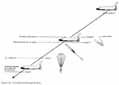
The following abort modes exist during the launch phase: return to the launch site, transatlantic abort landing, abort once around, and abort to orbit. Abort boundaries for these conditions are defined for each mission and are a function of vehicle weight and performance. Figure 30 provides a schematic representation of these modes.
Each Shuttle flight has abort techniques to ensure that, if orbital insertion cannot be realized, a runway landing can be achieved. These techniques, which protect against the loss of major vehicle system capability or loss of a single Space Shuttle main engine (SSME), are called intact aborts. Each intact abort trajectory is carefully tailored to avoid exceeding the vehicle structural and thermal load capability as a result of the aerodynamic forces encountered during atmospheric flight.
The on-board computer contains software for both the three SSME normal trajectory profiles and the two SSME intact abort mode trajectory profiles. These profiles are evaluated for each launch to ensure that they are acceptable for the specific wind conditions measured on the day of launch.
The loss of two or three SSME's (contingency abort) has always been recognized as a potential event for any Shuttle launch, and manual piloting procedures were in place to cover these engine failure cases. The procedures were developed in the Shuttle mission simulator at the Johnson Space Center and were primarily designed to accommodate the pilot interfaces with the orbiter flight control system and on-board software.
The contingency abort modes were not initially subjected to the formal program certification process because they were not included in the program design requirements. As part of the return-to-flight process, an assessment of all aspects of contingency aborts, including crew procedures, has been initiated. Emphasis is being placed on the determination of vehicle structural integrity [64] as it is exposed to the abort environments. Where structural concerns are indicated, changes to the procedures are being evaluated to determine their effectiveness in reducing the impacts. In those cases where piloting techniques are critical, with small tolerance for errors or deviations, automatic techniques are being evaluated for incorporation into the on-board software. The overall objective is to improve the probability of crew survival, either by achieving a runway landing at an abort site or by successfully flying the vehicle to within the conditions established for crew escape.
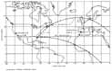
Shuttle launches from the Kennedy Space Center normally place the vehicle in one of two orbital inclinations: 28.5 degrees or 57 degrees. The ascent ground track profile for these typical launches is shown in Figure 31. Selected landing fields, as shown in the figure, are provided on the European and African continents for use in the event a transatlantic abort mode is required.
It is advantageous to have a landing site located near the ground track so that an abort landing can be achieved as quickly and safely as possible under minimum vehicle performance requirements. Dakar, Senegal, has provided this capability in the past for 28.5-degree launches; however, Dakar has some unfavorable topographic features and is not now considered to be acceptable as the "nominal" 28.5-degree landing site location. Several alternate locations along or near the ground track were assessed, and the landing field at Ben Guerir, Morocco, was selected as the prime 28.5-degree site. Equipment requirements for Ben Guerir have been identified and are being implemented to support the first flight.
|
Abort Mode |
| |
|
|
| |
|
. | ||
|
Return to Launch Site |
KSC |
KSC |
|
Transatlantic Abort Landing |
Ben Guerir, Morocco Moron, Spain |
Zaragoza/Moron, Spain |
|
Abort Once Around |
Edwards AFB/Northrop Strip |
Northrop Strip. |
The weather support equipment and landing aids at all transatlantic landing sites are being augmented to increase the potential for landing safely in the event of an abort.
RANGE SAFETY SYSTEM
The Commission suggested that NASA and the Air Force critically reexamine the need for retaining a destruct package on the external tank. A review team composed of NASA, Air Force, and range safety personnel has reviewed the total range safety system, including the destruct package, and found that it will operate and perform as designed. The issue of whether the external tank portion of the system could, or should, be removed is being assessed, and a decision is expected in mid-1988.
The Naval Surface Weapons Center is participating in this review and performing analyses of potential solid rocket booster breakup scenarios to assess the probability of booster debris destroying the external tank.
Guidelines and procedures governing range safety tasks at the launch site and in flight have been reviewed. Several issues require further action and are receiving attention from both NASA and Air Force management. Joint approval of updated range safety documentation will be obtained before first flight.
[66] DOCUMENTATION REVIEWS
Flight rules (which define the response to specific vehicle anomalies that might occur during flight) are being reviewed and updated. The Flight Rules Document is being reformatted to include both the technical and operational rationale for each rule. The review process is validating the performance limits set for each system and the data source for those limits.
Launch commit criteria (which define responses to specific vehicle and ground support system anomalies that might occur during launch countdown) are being reviewed and updated. These criteria are being modified to include the technical and operational rationale and to document any procedural work-arounds that would allow the countdown to proceed in the event one of the criteria was violated.
CREW ESCAPE
Although a final decision to implement a Space Shuttle crew escape system has not been made, the requirements for a capability to provide crew egress during controlled gliding flight have been established. Requirements for safe egress of up to eight crew members were determined through a review of vehicle escape routes, time lines, escape scenarios, and proposed orbiter modifications. The options for crew egress involve manual and powered extraction techniques. Design activities and wind tunnel studies have been initiated for each of these options.
Extraction techniques must ensure that the crew member does not contact the vehicle immediately after exiting the crew module. Several manual approaches being assessed for reducing the potential contact include a deployable tunnel that would provide sufficient initial velocity to preclude crew/vehicle contact and an extendable rod and/or rope that would place the crew release point in a safe region.
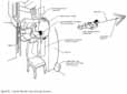
In the rod concept (Figure 32), the crew module hatch would be jettisoned and the rod would be extended through the hatch opening. The crew member would attach a lanyard to the rod, exit the vehicle in a tucked position, release at the end of the rod,....
[67].....and parachute to a ground or water landing. The powered extraction technique ensures that the crew will not contact the vehicle; however, it involves additional weight and crew compartment complexity and must be thoroughly evaluated to ensure that no safety hazards or additional risks would result from its implementation.
A study to determine the optimum powered extraction system for crew member egress was initiated in April 1986. This investigation included a review of possible escape routes and time lines, the effect of potential escape scenarios on the crew, and the weight and cost impact of required vehicle modifications. The study goal was to define a safe egress concept for up to eight crew members with minimal vehicle modification and weight penalties.
The study, completed in September 1986, considered ejection seats, tractor rocket extraction of seated crew members, bottom bail-out, and tractor rocket extraction through the side hatch. Each option considered the crew size, the required orbiter modifications, and the implementation schedule. These options are summarized in the following paragraphs.
An ejection seat concept that would extract up to five astronauts was assessed. During operation, this concept would jettison the tops of both the crew module and the forward fuselage before propelling the crew out of the opening in individual ejection seats. The addition of ejection seats would require major structural modification of the overhead consoles, flight deck floor, crew module structure, and forward fuselage structure.
A new ejection seat design would be required because the ejection seats used during the orbital flight test program are very large, and installation of five seats would affect orbiter aft flight deck payload station usage. The estimated first availability of the ejection seat concept is mid-1990. This concept is not being pursued because of late availability, extensive vehicle modifications, and crew size limitations.
Another extraction concept investigated was a tractor rocket system that would extract up to six seated crew members. Once activated, this system would jettison the tops of the crew module and forward fuselage and extract the crew using tractor rockets. This concept would require modification of the crew module and forward fuselage structure, the flight deck floor, and overhead consoles, and would affect payload station usage. The earliest availability of this modification is mid-1990. This configuration is no longer being pursued because of late availability, vehicle modification requirements, and crew size limitations.
A bottom bail-out concept that would provide safe egress for up to eight crew members was also assessed. In this concept, a panel would be opened on the bottom of the orbiter to deploy a guide chute, permitting the astronauts to exit the orbiter through the chute. This concept would require extensive structural modifications, including installation of a deployable panel and pyrotechnic devices to open the panel, design and installation of the chute, and relocation of some subsystem components. Modifications could potentially be completed and certified by 1989, but the concept is not being considered because of the highly complex vehicle changes required.
The final concept evaluated was escape through the side hatch using tractor rockets to propel the astronauts out of the orbiter. This method, which could safely extract up to eight astronauts, would require early venting of the crew module to equalize the crew module internal pressure with the external pressure. After venting is completed, the side hatch would be jettisoned. The crew members would then exit sequentially by using the tractor rockets. Required orbiter changes include addition of a cabin vent capability, modification of the side hatch structure to allow for hatch jettison, addition of pyrotechnic devices to jettison the hatch, and installation of the tractor rocket system.
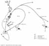
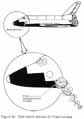
While a decision to implement the system has not been made, development of the side hatch extraction capability for use in a crew egress/escape system (CEES) has been authorized by the Director, NSTS. The system consists of a jettisonable crew hatch (also applicable to the manual bail-out mode), individual rockets to safely extract the crew from the vehicle, and personnel survival equipment. The crew escape sequence (Figure 33) would be initiated by venting the crew module to ensure that no pressure differential exists prior to hatch jettison. The side hatch would then be pyrotechnically jettisoned at approximately 22,000 feet (Figure 34). Crew escape would be initiated during controlled gliding flight at an altitude of 20,000 feet and a velocity of 200 miles per hour.
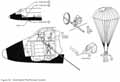
After the hatch is jettisoned, the crew moves to the hatch area and climbs onto a guide ramp. Each crew member attaches a tractor rocket pendant to their parachute/ survival pack. The crew member then activates the tractor rocket, and is extracted from the orbiter (Figure 35). Each crew member repeats this procedure until the commander exits at an altitude of approximately 10,000 feet. Minimum desirable ejection altitude is 5,000 feet.
Once the hatch is jettisoned, a crew of eight could nominally egress in less than 2 minutes. Each parachute/survival pack would include a parachute canopy, activated automatically at a predetermined altitude, a....
[69]....life raft, and other equipment required for survival while awaiting rescue.
System certification of the CEES will be based on component testing, full-scale integrated system tests, wind tunnel tests, and aircraft flight tests. Full-scale integrated system tests will be conducted combining all components of the newly designed equipment. Several tests will be performed to verify that the entire integrated system functions properly.
Aircraft tests are planned to verify design analysis and the operation of the tractor rockets during simulated flight conditions. During these tests, anthropomorphic dummies will be extracted from the side of an airplane modified to represent the orbiter configuration.
Although the decision on whether to incorporate the CEES, pursue one of the manual escape modes, or continue development of other approaches has not been made, the jettisonable hatch modification has been approved and will be installed prior to the first flight.
FIRST-STAGE-BOOST ESCAPE SYSTEM
A study to evaluate the feasibility of a future escape system to potentially enhance crew survival during first-stage flight (solid rocket boosters thrusting) has been initiated. Study objectives include determination of system cues required to indicate the need for escape, methods of escape initiation, and escape system design.
In support of this study, NASA has requested that the Naval Air Development Center lead a team of industry and Government escape system engineers in performing a detailed study of ejection seat concepts to determine the feasibility of using them in the Shuttle. NASA's Langley Research Center is performing a similar study of a system to provide....
[70]....rocket extraction capability from seated positions.
GROUND EGRESS
Emergency egress procedures for both crew and support personnel during the prelaunch period and after orbiter landing are being investigated. This assessment includes the hazards present during prelaunch and landing operations, the various systems for detecting the hazards, and possible egress routes.
A number of areas in the emergency egress capability that require improvement or further testing or evaluation have been identified. An emergency egress rescue working group has been chartered to resolve these issues.
A prelaunch pad egress simulation was conducted at the Kennedy Space Center in November 1986. In the test, an orbiter closeout and rescue crew conducted an end-to-end emergency egress with flight crew participation. Action items resulting from this exercise are being resolved. Another series of tests, to simulate postlanding egress, was conducted in April 1987, and a night pad egress exercise was successfully completed in June 1987. The results of both are being evaluated.
The large number of actions generated by these tests indicated that some of the existing equipment and procedures did not have adequate redundancy or simplicity for emergency use. Major modifications to the launch pad have been recommended, including a flame protection barrier for the access arm and launch pad structure, additional crew slide wire systems, and a new crew bunker. Other changes being considered include items such as improved armored personnel carriers for crew evacuation, new emergency breathing equipment, additional emergency lighting, and upgraded crew training.
Modifications to the launch pad and landing emergency equipment will be retested in end-to-end simulations for flight readiness certification. Periodic retesting will continue as a permanent part of the training and qualification process for launch and landing operations support personnel.
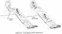
An egress slide (Figure 36) that can be used for emergency escape after landing is included in the CEES hardware development activity. This slide, which is similar to those used in commercial aircraft, will provide quick and safe egress for all members of the crew. In an emergency situation where the side hatch cannot be readily opened on the ground, the hatch can be jettisoned and the slide activated by the crew. The slide can also be used in a postlanding emergency, when the hatch can be opened but standard ground egress equipment is not available.