 |
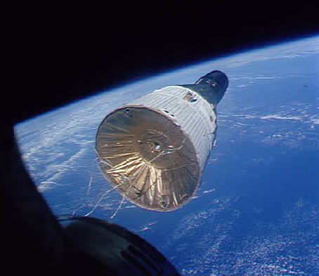
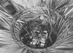
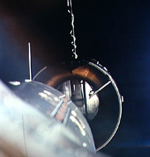
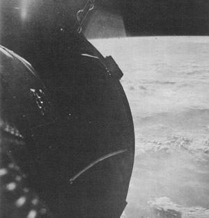
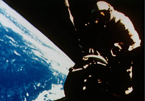
| Frontispiece: Gemini spacecraft No. 7 from the hatch of spacecraft No. 6 on December 15, 1965, during the first successful rendezvous of manned spacecraft in Earth orbit (NASA Photo S-65-63221, Dec. 15, 1965) |
|
|
| Frontispiece: Gemini spacecraft No. 7 from the hatch of spacecraft No. 6 on December 15, 1965, during the first successful rendezvous of manned spacecraft in Earth orbit (NASA Photo S-65-63221, Dec. 15, 1965) |
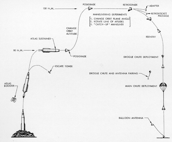
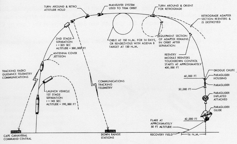
Figure 1: Proposed mission for modified Mercury capsule.
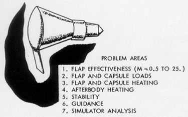
Figure 2: Early version of "lifting" Mercury capsule.
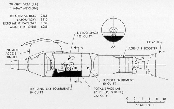
Figure 3: Proposed version of one-man space station.
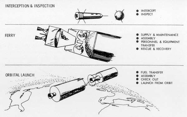
Figure 4: Orbital operations requiring a rendezvous development program.
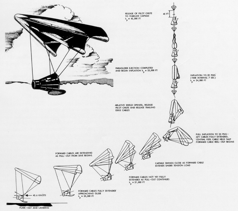
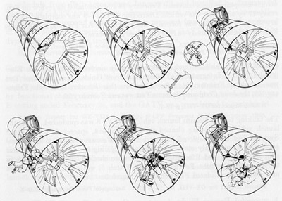
Figure 5: Deployment sequence for Mercury paraglider.
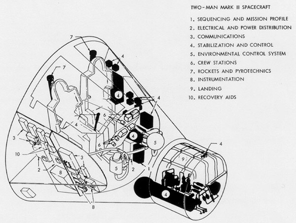
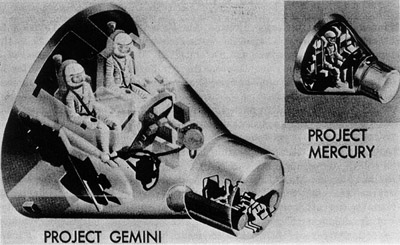
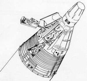
Figure 6: Interior arrangement for proposed two-man Mercury spacecraft.
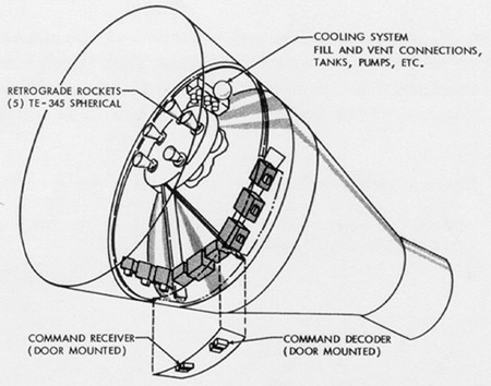
Figure 7: Adapter section of proposed two-man Mercury spacecraft.
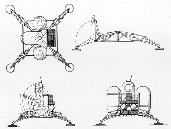
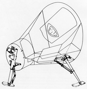
Figure 8: Proposed "Lunar Lander" for use with advanced Mercury spacecraft: Artist's conception.
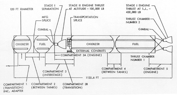
Figure 9: Drawing of modified Titan II for launch of advanced Mercury.
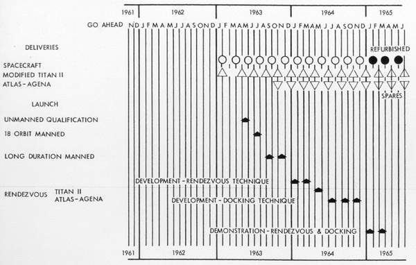
Figure 10: Launch schedule for final version of Mark II Project Development Plan.
Figure 11: First publicly released illustration of Gemini spacecraft.
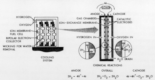
Figure 12: Operating principle of General Electric fuel cell for Gemini.
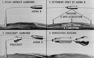
Figure 13: Early conception of rendezvous mission.
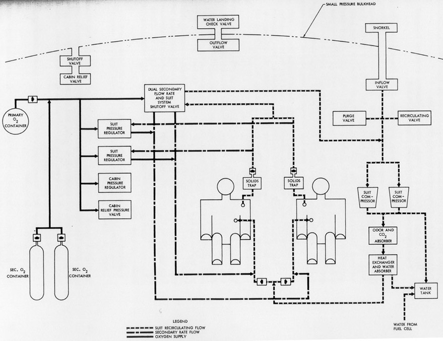
Figure 14: Block diagram of Gemini environmental control system.
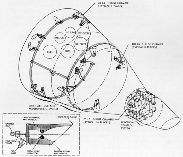
Figure 15: General arrangement of liquid rocket systems in the Gemini spacecraft and typical thrust chamber assembly.
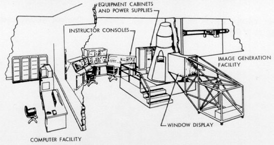
Figure 16A: Gemini flight trainer for crew training.
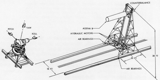
Figure 16B: Gemini docking trainer for crew training.
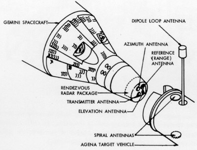
Figure 17: Main elements of the radar rendezvous system on Gemini spacecraft and Agena target vehicle.
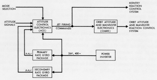
Figure 18: Block diagram of the attitude control and maneuvering electronics system of Gemini spacecraft.
Figure 19: Gemini spacecraft landing gear for land landing with the paraglider.
Figure 20: Election seats in the Gemini spacecraft: Artist's conception.
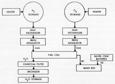
Figure 21: Reactant supply system for Gemini fuel cells.
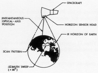
Figure 22: Operation of the horizon sensor for Gemini spacecraft.
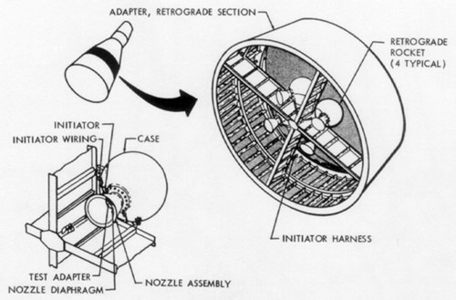
Figure 23: Retrograde rocket system for the Gemini spacecraft.
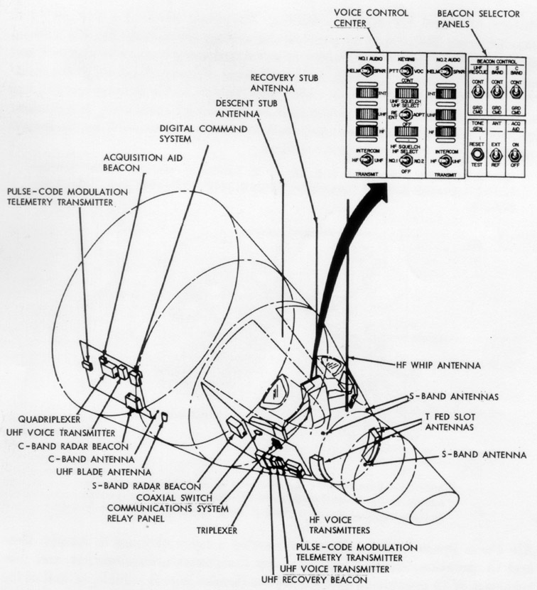
Figure 24: Gemini spacecraft communications system.
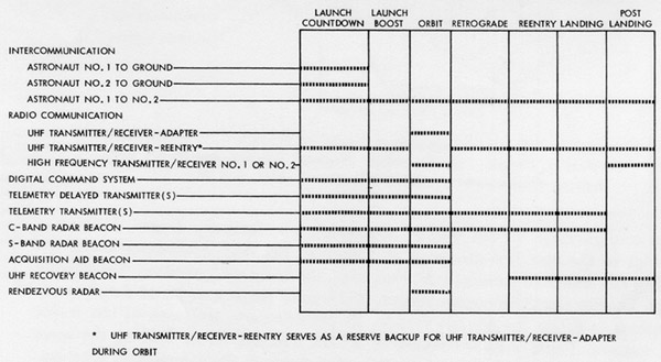
Figure 25: Table showing communication functions during a mission.
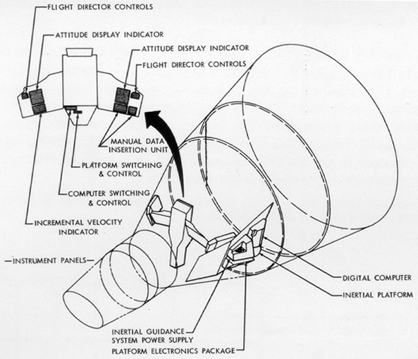
Figure 26: Inertial guidance system.
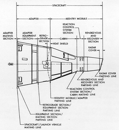
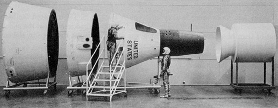
Figure 27: General nomenclature of the Gemini spacecraft.
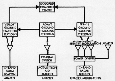
Figure 28: Gemini spacecraft tracking aids.
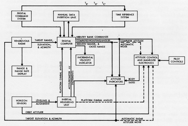
Figure 29: Block diagram of the Gemini spacecraft guidance and control system.
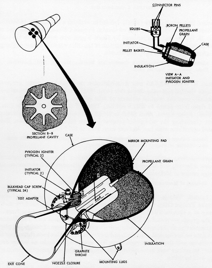
Figure 30: Solid-propellant retrograde rocket motor.
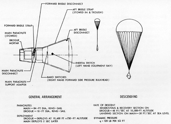
Figure 31: Parachute recovery system for the first Gemini spacecraft.
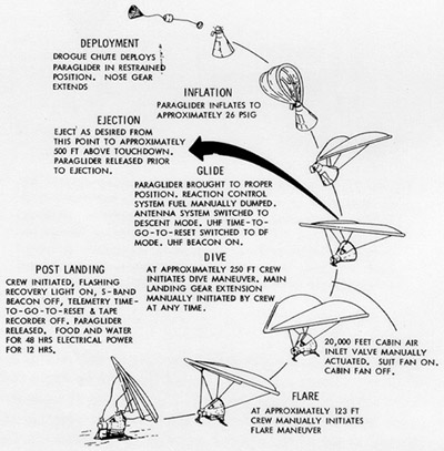
Figure 32: Paraglider deployment sequence of events.
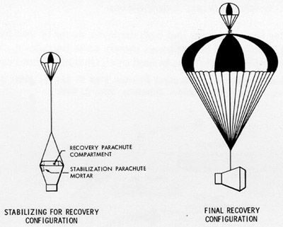
Figure 33: Emergency parachute recovery system for half-scale paraglider flight test vehicle.
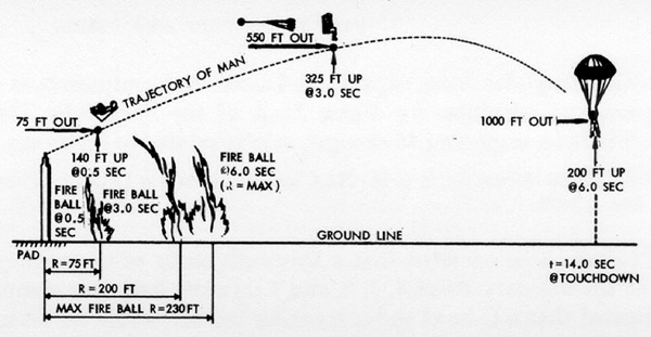
Figure 34: "Off-the-pad" escape mode for aborted Gemini mission.
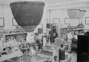
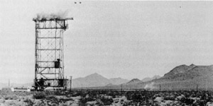
Figure 35: Airborne systems functional test stand at Martin-Baltimore.
Figure 36: Emergency parachute recovery system for full-scale paraglider flight test vehicle.
Figure 37: Engineering mockup of Gemini spacecraft at McDonnell, St. Louis.
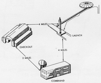
Figure 38: Proposed layout of Gemini facilities at Cape Canaveral.
Figure 39: Sequence of events for Gemini missions.
Figure 40: Proposed sequence of events for first Gemini mission.
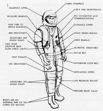
Figure 41: The B.F. Goodrich partial-wear full-pressure suit for Gemini.
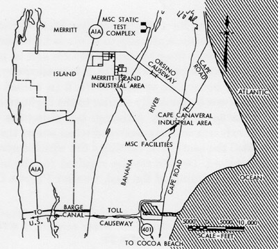
Figure 42: Manned Spacecraft Center Gemini facilities at Cape Canaveral and Merritt Island Launch Area.
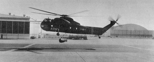
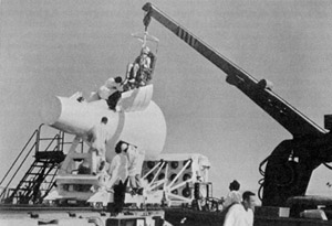
Figure 43: Paraglider half-scale test vehicle being lifted by helicopter.
Figure 44: Ten percent model of Gemini spacecraft used for wind tunnel testing at McDonnell.
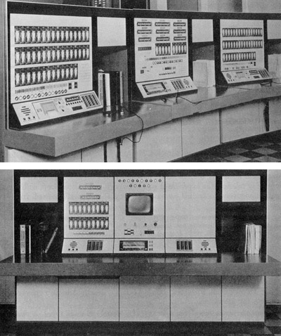
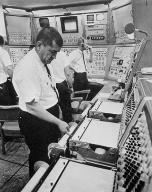
Figure 45: Consoles in tracking network remote stations.
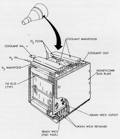
Figure 46: Gemini fuel cell stack.
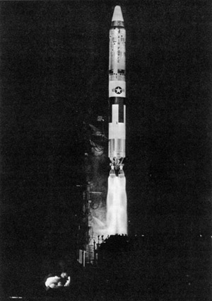
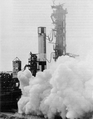
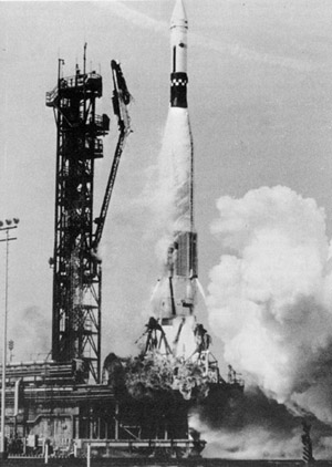
Figure 47: Titan II N-15 launch at Cape Canaveral.
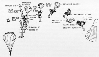
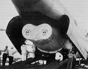
Figure 48: Ballute deployment.
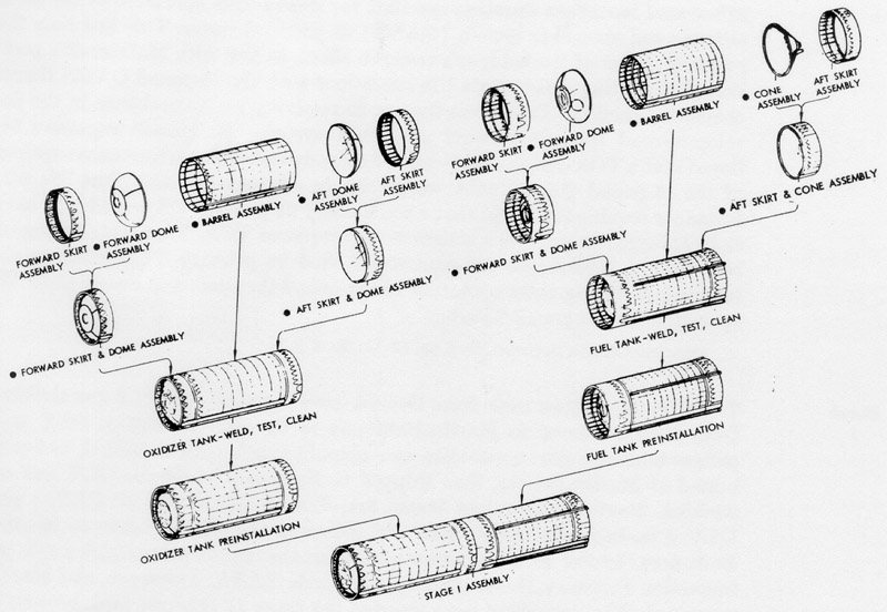
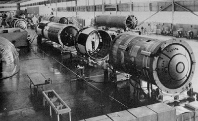
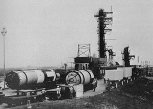
Figure 49A: Assembly of Gemini launch vehicle fuel and oxidizer tanks for Stage I.
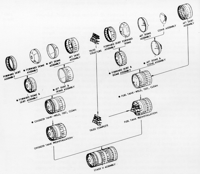
Figure 49B: Assembly of Gemini launch vehicle fuel and oxidizer tanks for Stage II.
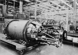
Figure 50: Primary propulsion system of Gemini Agena target vehicle.
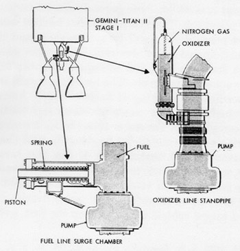
Figure 51: "POGO" suppression equipment.
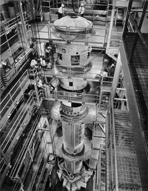
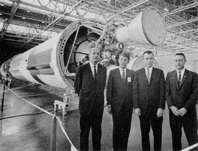
Figure 52: Gemini Launch Vehicle 1 being tested in Martin's vertical test facility in Baltimore.
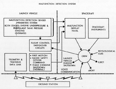
Figure 53A: Malfunction detection system, (diagram), showing interface with Gemini spacecraft.
Figure 53B: Malfunction detection system, (panel display).
Figure 54: Preparation of Gemini ejection seat for a dynamic sled test.
Figure 55: Reentry control system for Gemini Spacecraft No. 1.
Figure 56: Preparation for a test run in the cenrifuge at Johnsville, Pennsylvania.
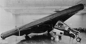
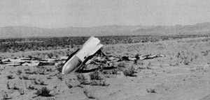
Figure 57: Paraglider full-scale test vehicle.
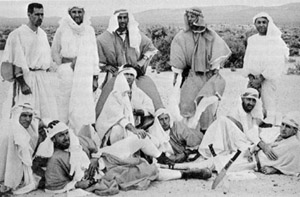
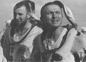
Figure 58: Desert training for astronauts.
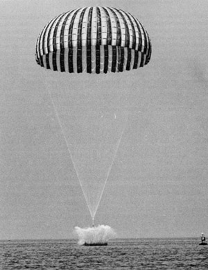
Figure 59: Water impact test of the Gemini parachute recovery system.
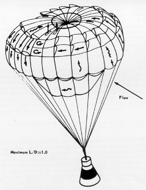
Figure 60: Proposed parasail landing system: Artist's conception.
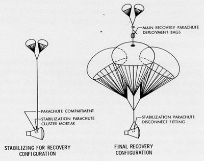
Figure 61: Gemini parachute recovery system operational sequence.
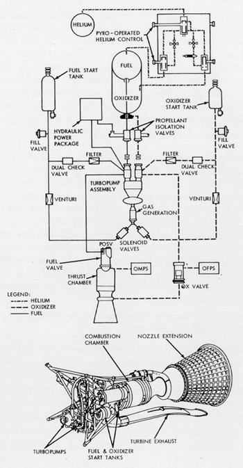
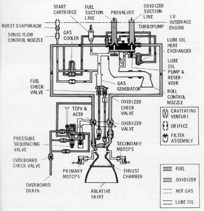
Figure 62: Diagram of the Gemini launch vehicle Stage II engine.
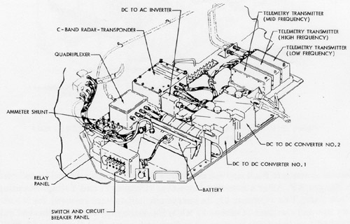
Figure 63A: Instrumentation pallet, (left), for Gemini spacecraft No. 1.
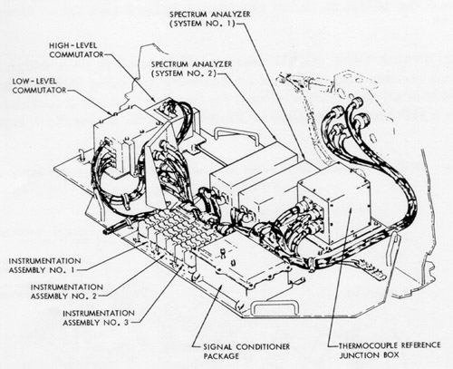
Figure 63B: Instrumentation pallet, (right), for Gemini spacecraft No. 1.
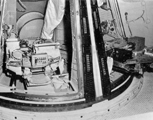
Figure 64: Installation of right ballast pallet and instrumentation pallet in Gemini Spacecraft No. 1.
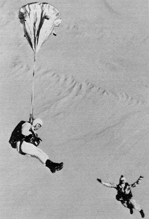
Figure 65: Jump-testing the 36-inch ballute at El Centro, California.
Figure 66: Sequence compatibility firing of both stages of Gemini Launch Vehicle 1.
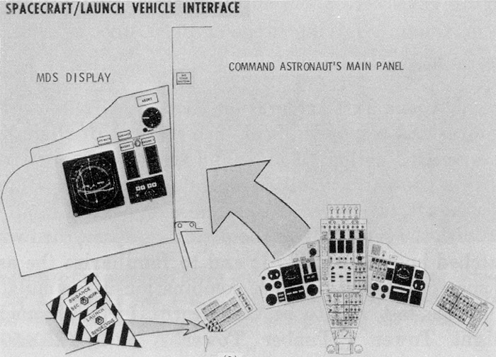
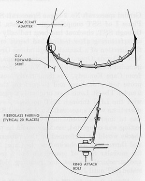
Figure 67: Interface between Gemini launch vehicle and spacecraft.
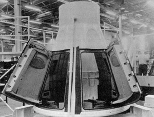
Figure 68: Gemini Boilerplate 3A in the production area at McDonnell.
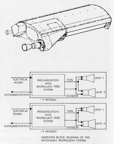
Figure 69: Agena secondary propulsion system.
Figure 70: Electronic- electrical interference tests of Gemini-Titan 1.
Figure 71: Parachute test vehicle.
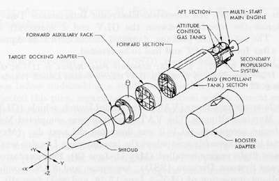
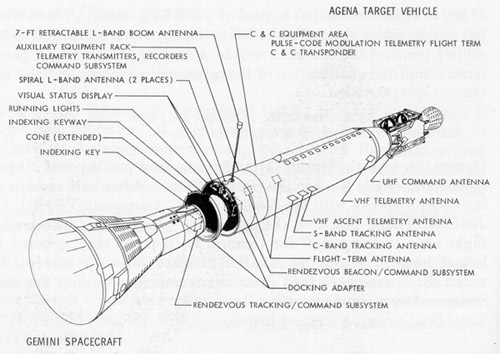
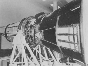
Figure 72: Configuration of the Gemini Agena target vehicle.
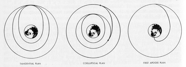
Figure 73: Three basic rendezvous plans considered for the first rendezvous mission in Gemini.
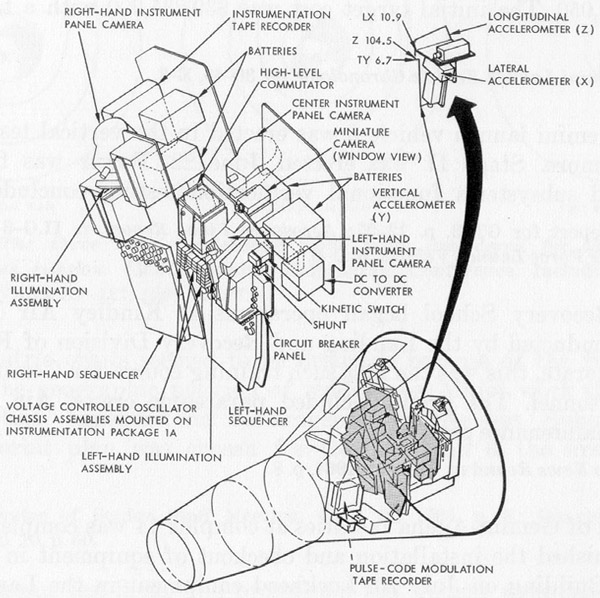
Figure 74: Special insrumentation pallets for Gemini Spacecraft No. 2.
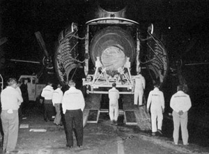
Figure 75: Unloading of Gemini Launch Vehicle 2 first stage at Cape Kennedy.
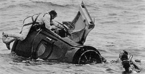
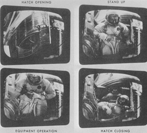
Figure 76: Egress training in Galveston Bay.
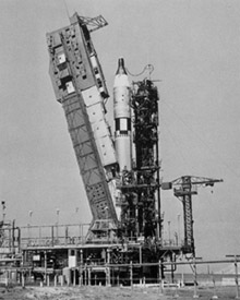
Figure 77: Gemini Launch Vehicle 3 undergoing final checks.
Figure 78: Backup and prime crews for Gemini-Titan 3 at Rollout Inspection for launch vehicle.
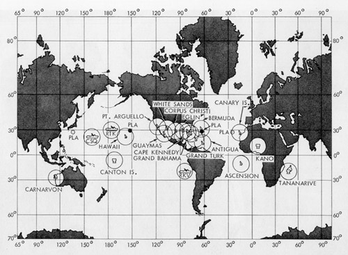
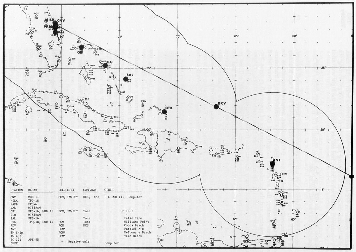
Figure 79: Gemini network.
Figure 80: Water egress training at Ellington Air Force Base, Texas.
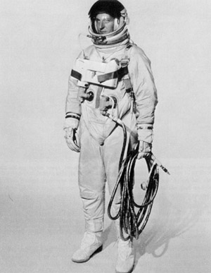
Figure 81: Gemini G4C extravehicular suit.
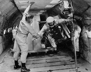
Figure 82: Zero-G tests in a KC-135.
Figure 83A: Astronauts Grissom and Young in the Gemini mission simulator at Cape Kennedy.
Figure 83B: Technicians at consoles of the Gemini mission simulator at Cape Kennedy.
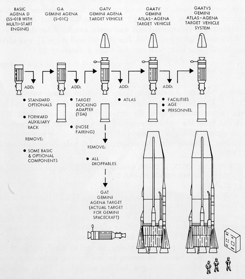
Figure 84: Agena Target Vehicle program terminology.
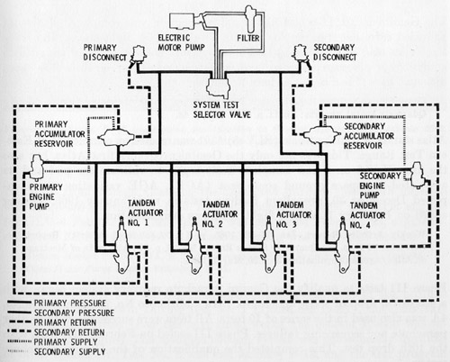
Figure 85: Gemini Launch Vehicle Stage I hydraulic system.
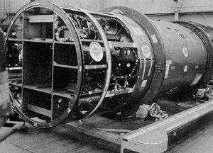
Figure 86: Agena D 82 being modified to Gemini Target Vehicle 5002.
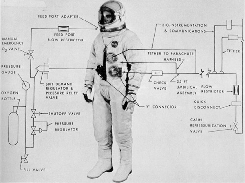
Figure 87: Gemini G4C extravehicular suit with chest pack and umbilical.
Figure 88: Gemini Spacecraft No. 3 being unloaded at Cape Kennedy.
Figure 89: Simulated Off-the Pad Ejection Test No.13 at China Lake, California.
Figure 90: Tracking network for the second Gemini mission.
Figure 91: Gemini Launch Vehicle 5 erection at the vertical test facility, Martin-Baltimore.
Figure 92: Agena target vehicle command and communication system locations.
Figure 93: Gemini-Titan 3 on pad 19.
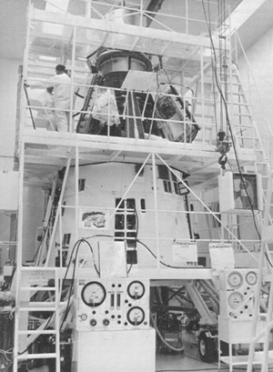
Figure 94: Gemini Spacecraft No. 4 entering altitude chamber at McDonnell.
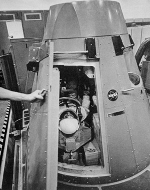
Figure 95: Extravehicular activity practice in the altitude chamber at McDonnell.
Figure 96: Astronauts Young and Grissom walking toward elevator on pad 19.
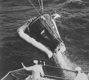
Figure 97: Gemini Spacecraft No. 3 being hoisted aboard recovery ship.
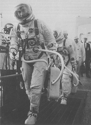
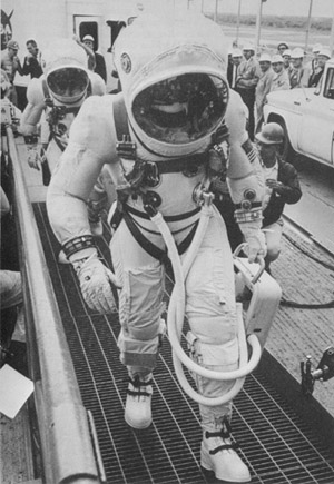
Figure 98: Astronaut James A. McDivitt undergoing wet mock simulated launch.
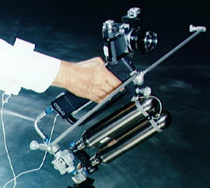
Figure 99: Hand-held maneuvering unit.
Figure 100: Gemini Spacecraft No. 5 cleanup.
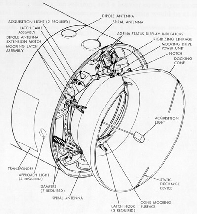
Figure 101: Target docking adapter assembly.
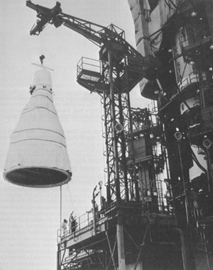
Figure 102A:Launch vehicle erector tower being lowered.
Figure 102B:Gemini-Titan 4 launch.
Figure 103: Gemini-Titan 4 extravehicular activity.
Figure 104: Rendezvous evaluation pod in the equipment section of Gemini Spacecraft No. 5.
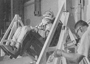
Figure 105: Gemini 5 ingress practice.
Figure 106: Agena target launch vehicle being delivered to final assembly area.
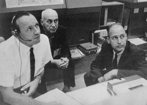
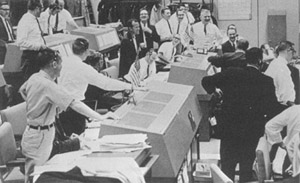
Figure 107: Mission Control Center, Houston, during Gemini 5 mission.
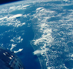
Figure 108: Florida peninsula from Gemini 5.
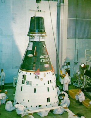
Figure 109: Gemini Spacecraft No. 7 in clean room at McDonnell.
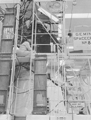
Figure 110: Gemini Spacecraft No. 8 in McDonnell's clean room.
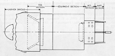
Figure 111A:General arrangement of augmented target docking adapter.
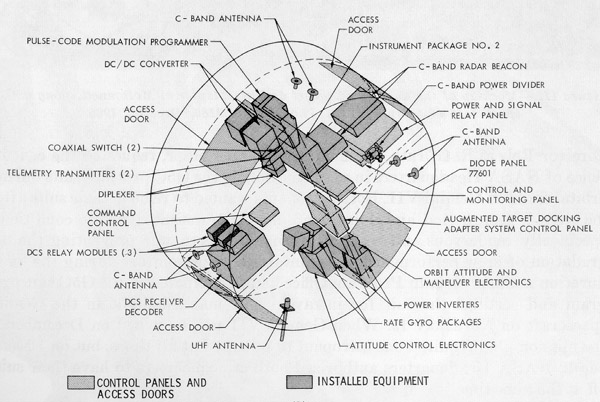
Figure 111B:Augmented target docking adapter equipment.
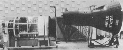
Figure 112: Mockup of augmented target docking adapter and Gemini spacecraft at McDonnell.
Figure 113: Gemini VII crew walking toward elevator at pad 19.
Figure 114: Gemini VII crew on deck of U.S.S. Wasp after recovery.
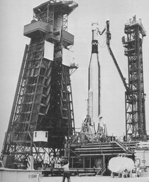
Figure 115: Gemini Spacecraft No. 6 being hoisted at complex 19.
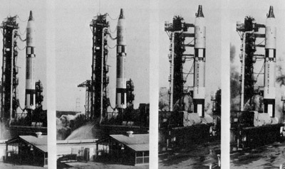
Figure 116: Attempted launch and shutdown of Gemini VI-A.
Figure 117: Houston Mission Control Center reaction to first rendezvous.
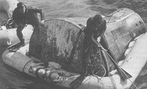
Figure 118: Swimmers attaching cable to Gemini VI-A spacecraft after landing.
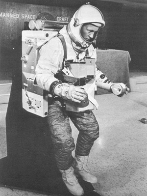
Figure 119: Donning the astronaut maneuvering unit.
Figure 120: Launch of Gemini Atlas-Agena target vehicle for Gemini VIII mission.
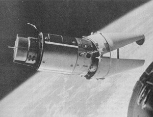
Figure 121A:Final stage of Gemini VIII and Gemini Agena target vehicle rendezvous.
Figure 121B:Gemini VIII and Agena in docked configuration.
Figure 122: Demonstration of astronaut maneuvering unit.
Figure 123: Augmented target docking adapter with shroud still attached.
Figure 124: Gemini Launch Vehicle 11 Stages I and II arriving at complex 19.
Figure 125: Gemini Atlas-Agena target vehicle for Gemini X at complex 14.
Figure 126: Gemini XI spacecraft in the pyrotechnic installation building at Merritt Island Launch Area.
Figure 127: Gemini XI astronaut returns to spacecraft hatch.
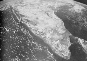
Figure 128: View of India and Ceylon during the Gemini XI mission.
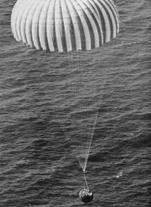
Figure 129: Gemini XI during landing phase.
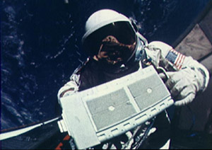
Figure 130: Gemini XII astronaut with micrometeoroid package.
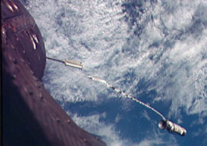
Figure 131: Tethered operation during Gemini XII.


