This article considers the utilisation of modern image processing and enhancement to determine the impact of the catastrophic failure of Cryogenic Oxygen Tank 2, and it's subsequent impact on Bay 4 and critical systems on Apollo 13. The analysis also aims to aid visualisation and identify key components of the damaged Service Module.
Details of the original photographic analysis which formed a significant part of the 1970 investigation can be found in Apollo 13 document collection with particular reference to the following documents:
• Apollo 13, Panel 1, Spacecraft Incident Investigation, Volume 1, Anomaly Investigation - 1970-06-10. PDF File (32.5 MB)
• Apollo 13, Panel 4, Photo Handling, Processing and Cataloguing - 1970-05-18. PDF File (2.95 MB)
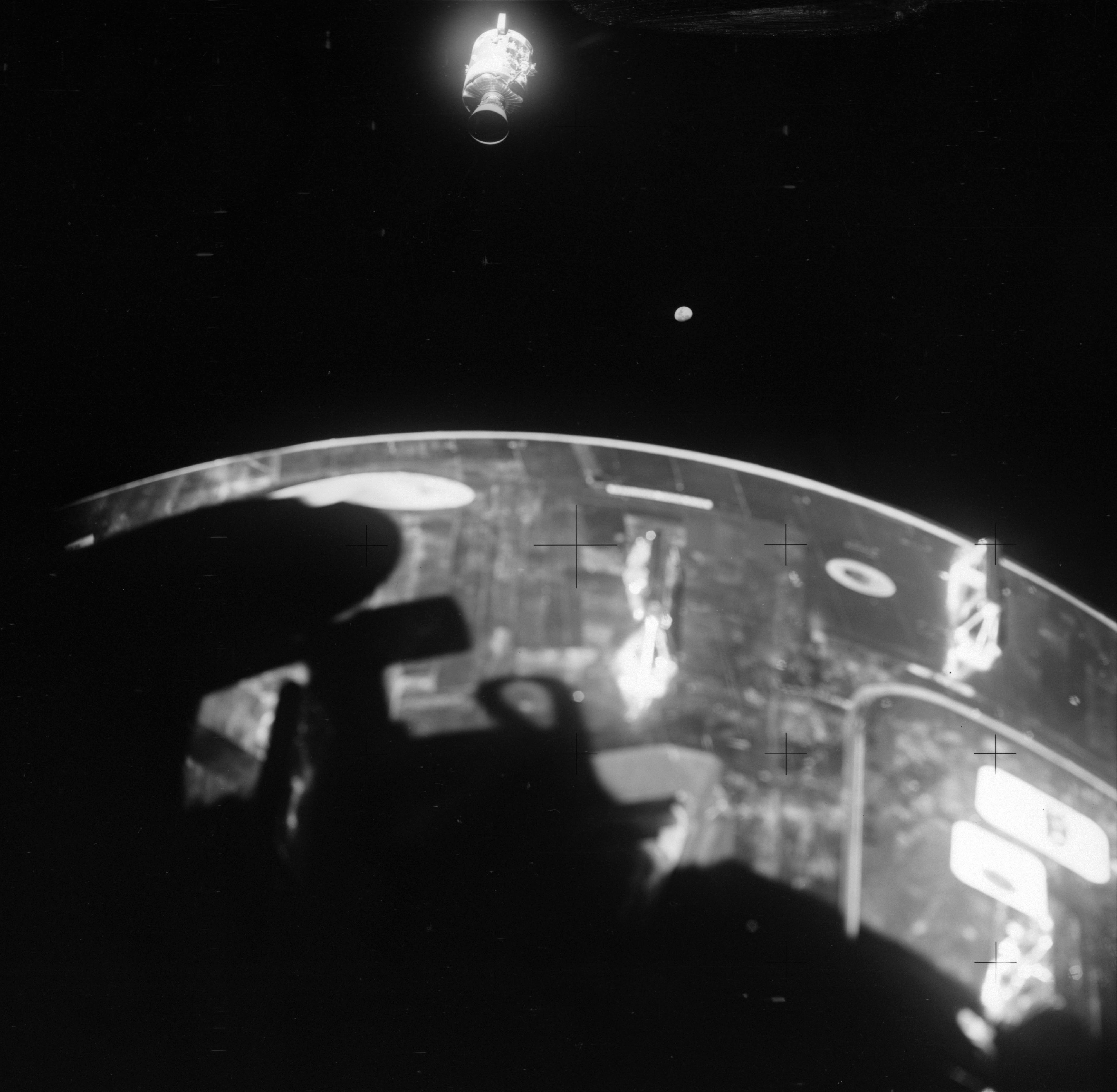
As in the original 1970 investigation report, there were key images taken by the crew through the window of Lunar Module 'Aquarius', shortly after the Service Module separated from the Command Module. These include:
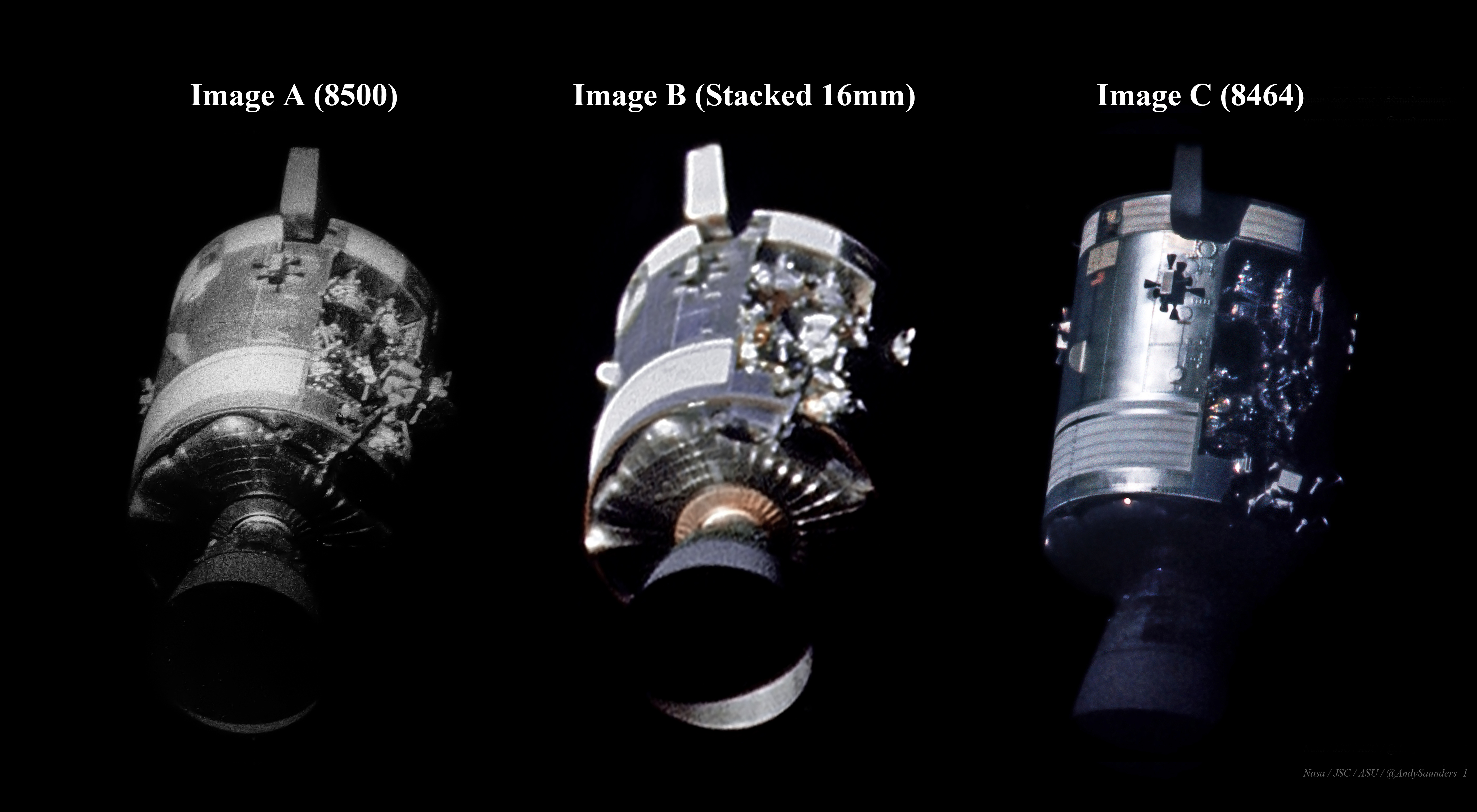
AS13-59-8500 - Hasselblad 70mm B&W, 80mm lens. Taken from a distance of c.410 feet. This is the source for Figure 1, Image A.
Apollo 13 - 16-mm film magazine 1151-FF, 75mm lens. This is the source for Figure 1, Image B.
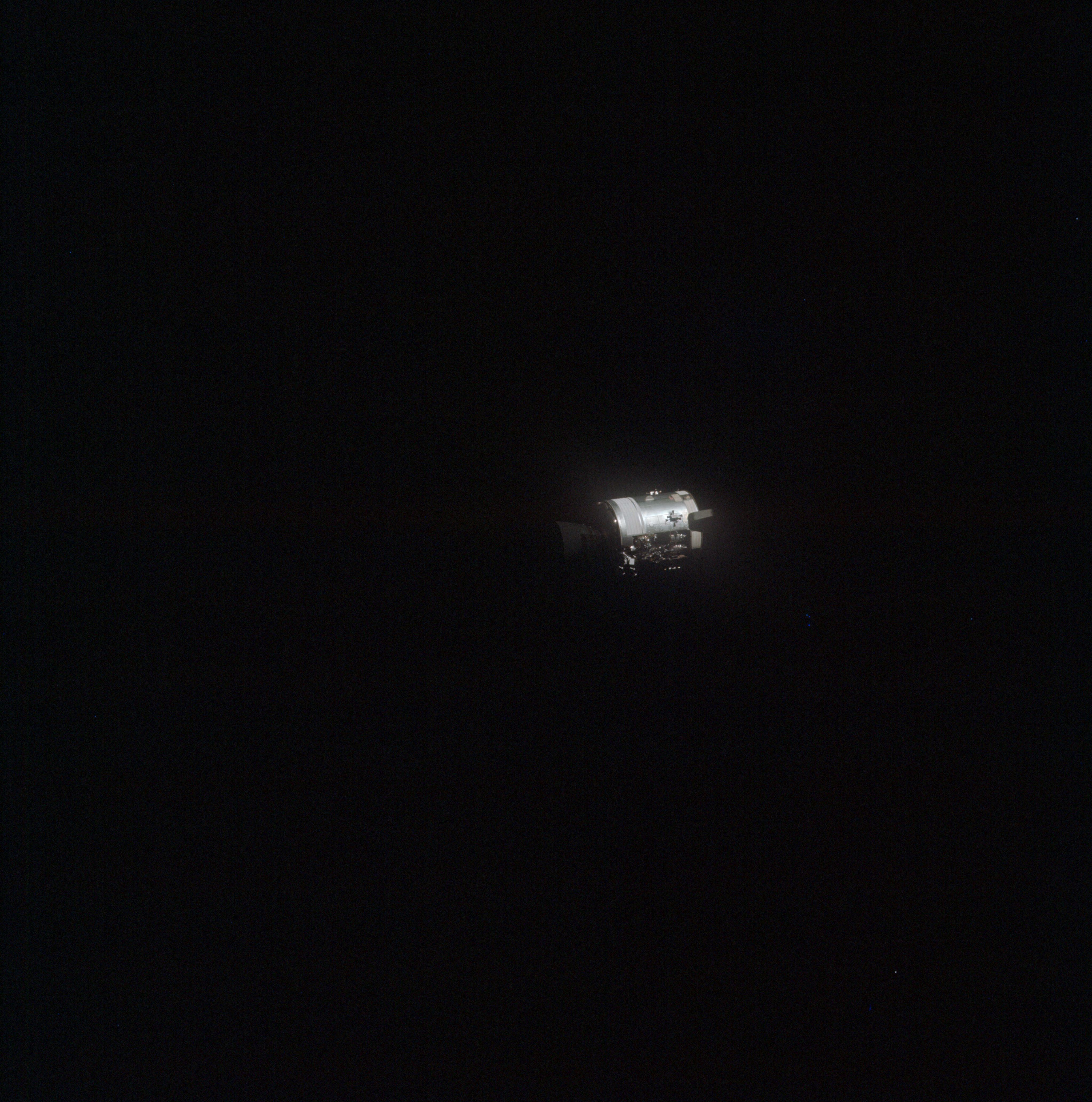
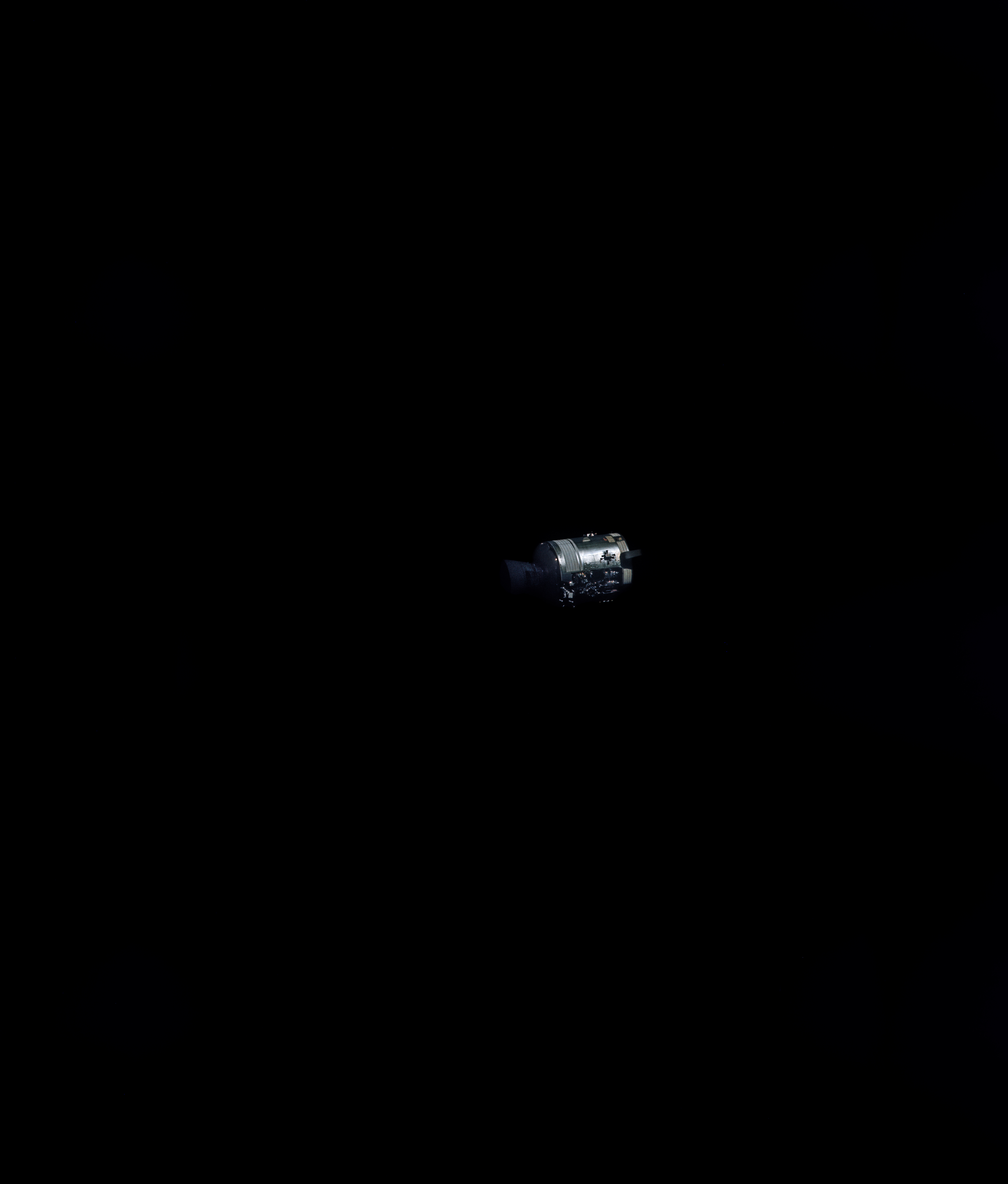
AS13-58-8464 - Hasselblad 70mm Colour, 250mm lens, f/5.6. Taken from a distance of c.880 feet. This is the source for Figure 1, Image C.
Image Processing and Results:
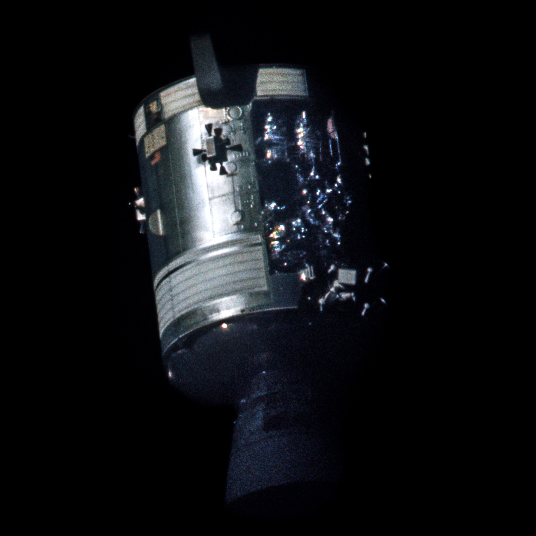
Figure 1. These three images of the jettisoned SM have been derived from the Apollo material above. Image reprocessing: Andy Saunders (Click for the full size version.)
Image A (from 8500) is the most commonly referenced image showing SM damage and is an enhanced crop of the full frame. Further minor enhancement has been made by Andy Saunders to improve clarity and localised contrast.
Image A yields a reasonable level of contrast and detail, particularly in the damaged Bay 4 area. A hint of a dark stain is also visible on the engine nozzle.
Image B (from 16mm film magazine 1151-FF) is, in fact, 8 separate 16mm video frames aligned, stacked, and processed by the author. This is a technique typically utilised in modern digital astrophotography and works on the principle that every image contains signal and noise, but the noise is truly random.
Noise may be caused by the grain structure of the 16mm film medium, in addition to digital noise introduced in the film transfers. By aligning and stacking multiple image samples of the same subject, individual values for each aligned feature in the stack can be averaged out, thus reducing noise whilst maintaining signal. The more sample images, the better the averaging, with the improvement in the signal/noise ratio equal to the square root of the number of stacked images. The stacked image has then undergone some wavelet and post-processing. Credit goes to Stephen Slater for providing high quality scans of the original film.
Image B is a very similar angle to Image A and the stacking process has revealed a surprising amount of detail for hand held 16mm camera footage. This image holds the best colour information of the three images (note the Kapton/Mylar blown loose from Bay 4). Of particular note in this new image however, is the apparent damage to the engine nozzle – more significant than has previously been indicated in the Hasselblad frames.
Image C (8464) is one of 26 similar frames taken in succession by the crew and reveals the most detail within Bay 4 due to optimum illumination/Sun angle. The original Hasselblad transparency has been removed from cold storage and rescanned by Johnson Space Center at 200 pixels/mm and extended bit depth (14-bit A/D). Arizona State University then made the original scan available by way of a 1.3GB TIFF file.
The resultant raw film scan has then been extensively remastered by the author to reveal an exceptional level of detail. The full image has been cropped and rotated to a more familiar orientation.
Image C is at a more favourable angle to illuminate Bay 4 and highlight the damaged area. The new processed image yields an exceptional level of clarity and detail, with even individual mechanical fixings in the panelling visible and fuel cells prominent.
Photographic Damage Analysis Utilising Image C:
Figure 2. The full frame of processed Image C (AS13-58-8464) aids perspective as viewed and photographed by the crew in the Lunar Module c.880ft away. Image reprocessing: Andy Saunders. (Click for the full size version.)
This frame is then zoomed (cropped) and rotated into a more familiar orientation:
Figure 3. A cropped image of the Service Module from processed Image C. Image reprocessing: Andy Saunders. (Click for the full size version.)
What remains of Bay 4 is now more visible, the panel of which was blown off due to a pressure build-up caused by the catastrophic failure of cryogenic oxygen tank 2. Where exactly was the explosion that caused the failure of critical systems on Apollo 13? What is still visible in Bay 4 after the failure? Exactly what collateral damage was caused?:
In order to aid visualisation of the damage, two further photographs have been utilised. Pre-flight, close-out photographs of Bay 4 taken at North American Rockwell prior to shipping to KSC have been obtained via San Diego Air and Space Museum:
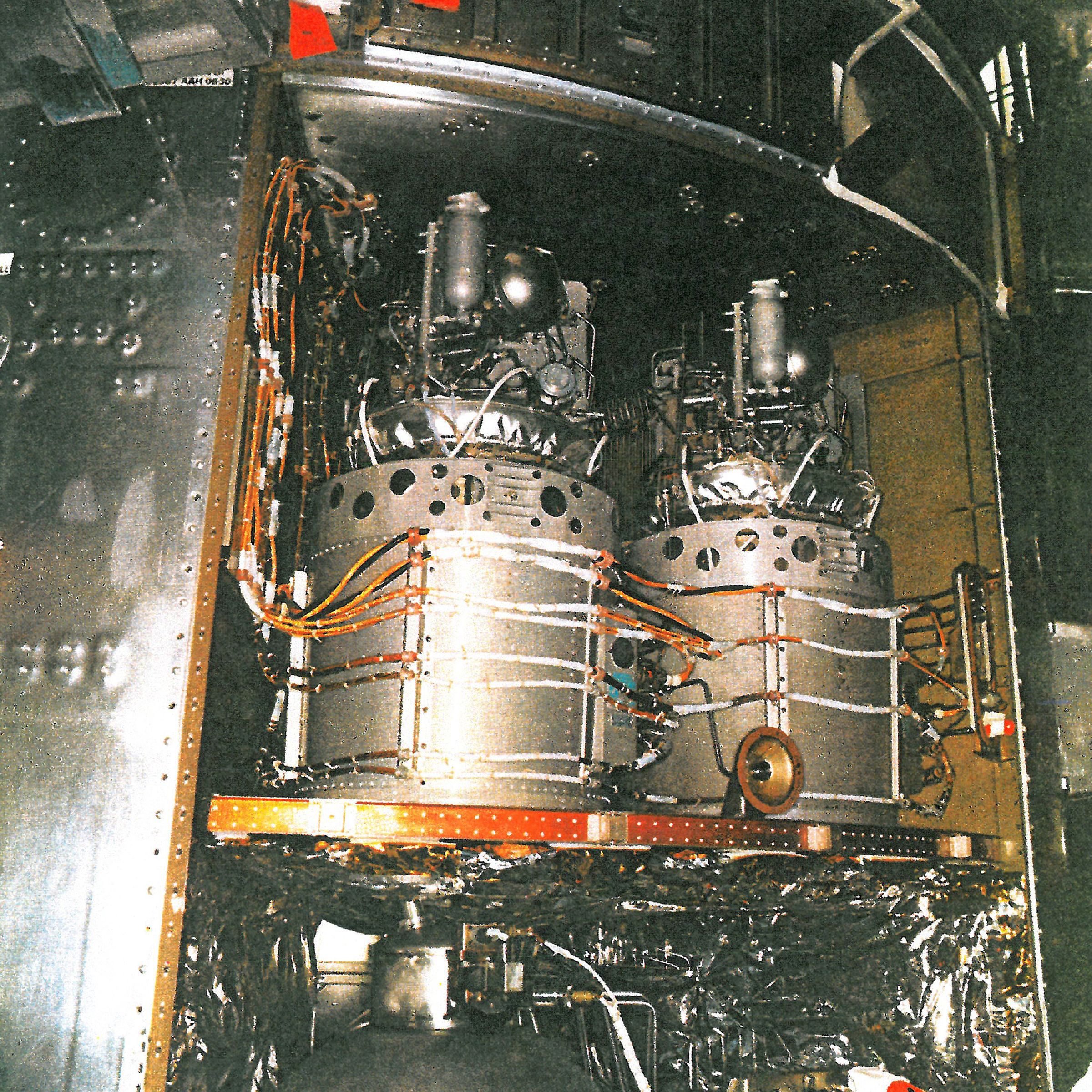
Figure 4. The upper part of Bay 4 of Apollo 13's Service Module. This contained the spacecraft's three fuel cells. (Click for the full size version.)
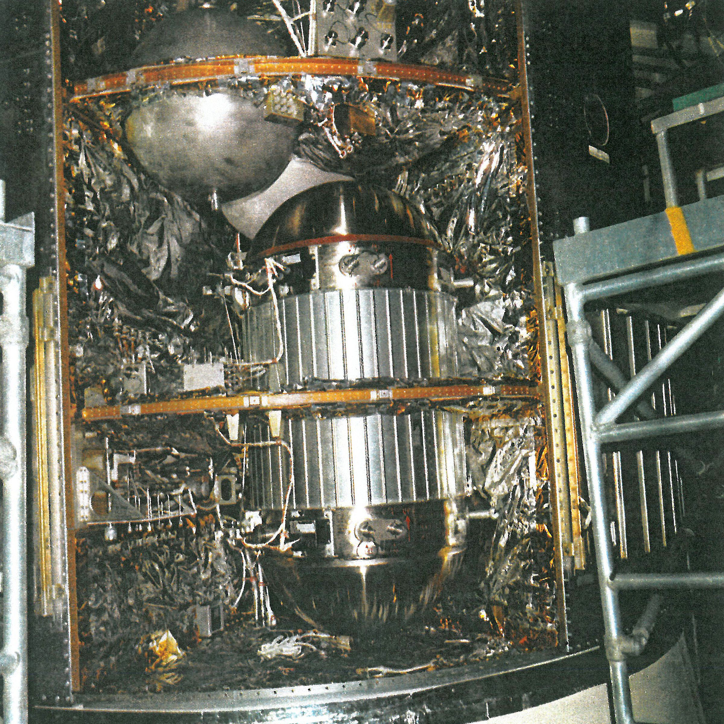
Figure 5. Bay 4 of Apollo 13's Service Module. This contained the spacecraft's oxygen and hydrogen tanks for power generation and breathing air. (Click for the full size version.)
The same images were used in the 1970 investigation, however with modern photo-processing technology the images can be combined and distorted to take account of perspective, overlayed and lined up with key geometric features on the SM body in Image C:
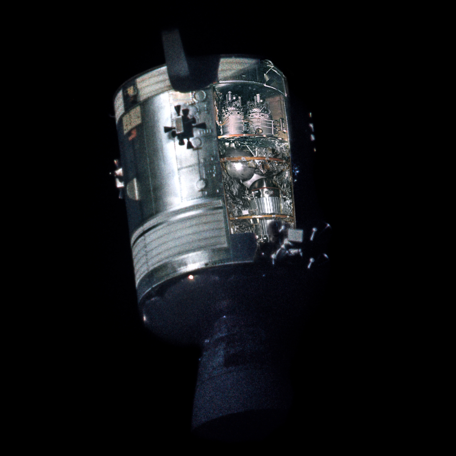
Figure 6. Preflight photos aligned with post-jettison SM picture 8464. Image processing: Andy Saunders. (Click for the full size version.)
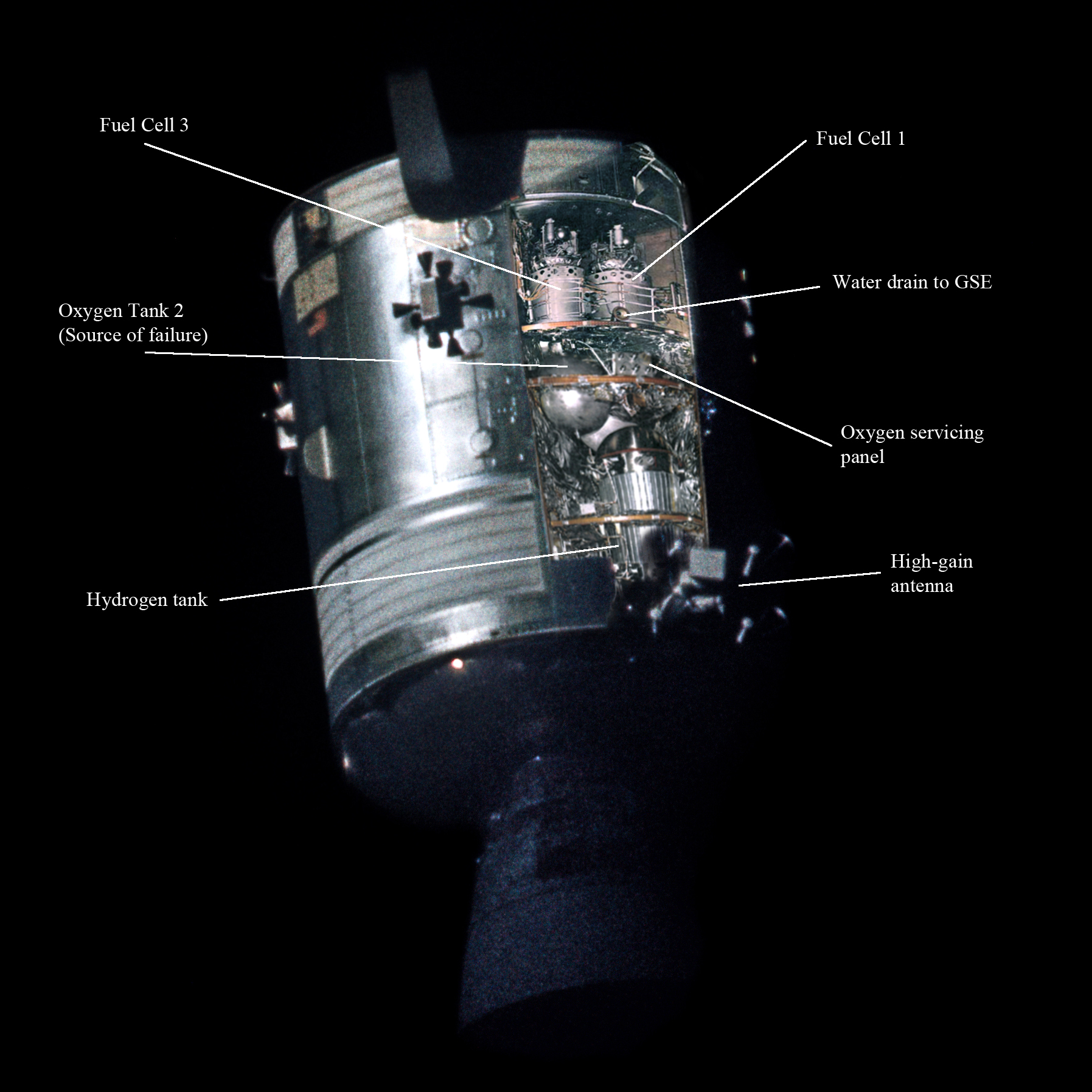
Figure 7. Labelled version of above showing key components within Bay 4. (Click for the full size version.)
Gradually reducing the opacity of the pre-flight images now reveals the detail inherent in Image C and the changes caused by the failure of oxygen tank 2:
Figure 8. Animation to gradually remove preflight overlays. Image processing: Andy Saunders.
A labelled version of Image C highlights key observations in conjunction with the 1970 report:
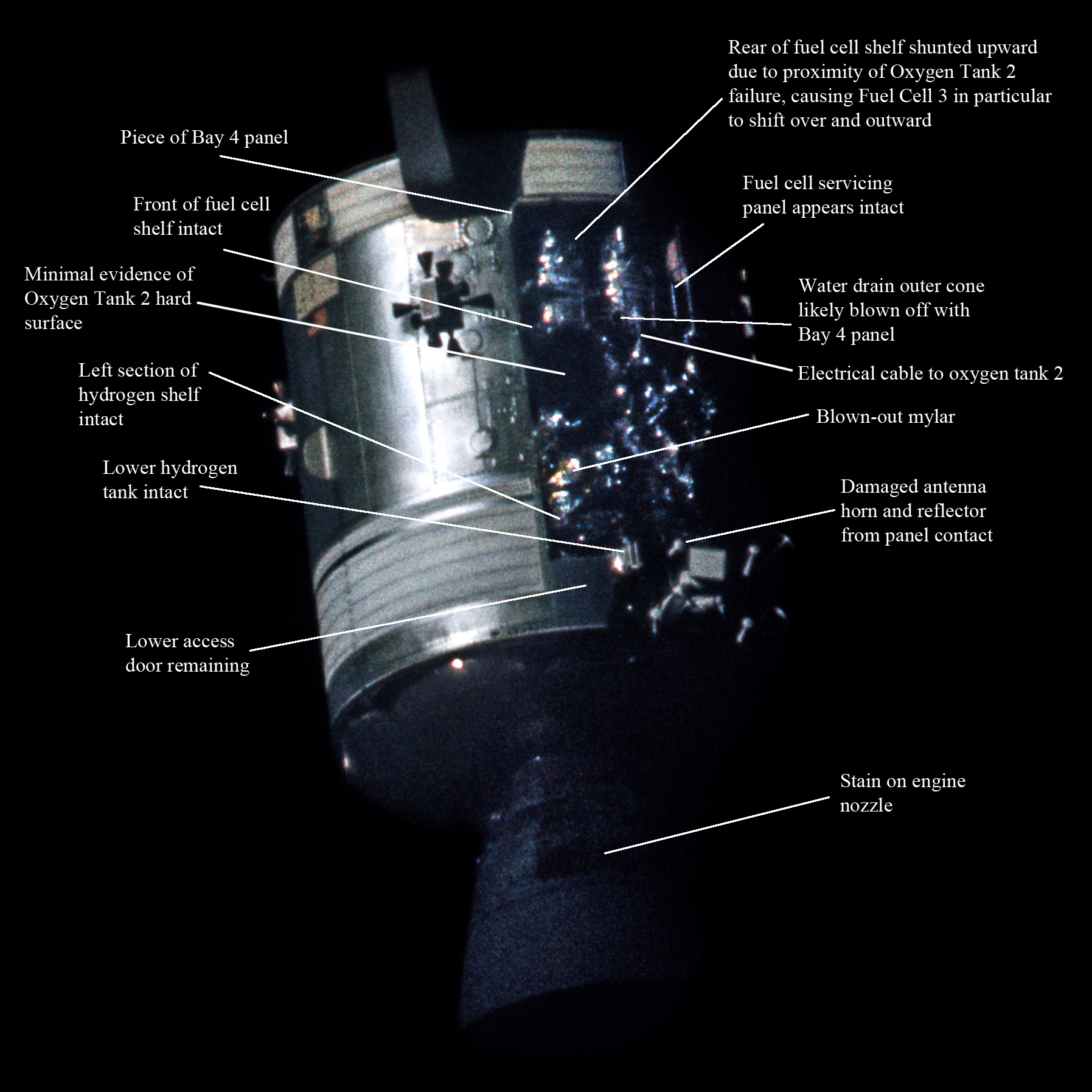
Figure 9. (Click for the full size version.)
• Both fuel cells, but particularly fuel cell 3 (directly above oxygen tank 2) appear to be tipped outboard indicating a lifting of the rear of the oxygen shelf as a result of the blast (the front of the shelf above oxygen tank 2 appears undamaged and in place however).
• Mylar and Kapton insulation was blown, torn or burned free from it's initial fastening.
• The electrical cable/connection to oxygen tank 2 was blown out and upward from the shelf fixing location.
• The water drain to ground support equipment appears damaged but in position.
• The hydrogen tank and some connections are visible and appear intact and in the correct position.
• A small (6inch x 4inch) part of the Bay 4 panel remains attached at the upper left corner adjacent to radial panel 3 and the lower left access panel remains in position.
• One of the high gain antenna's reflectors and horn has been damaged / deflected.
• The left side of the hydrogen shelf appears intact and in position.
• A brown stain is observed on the SM engine nozzle.
The 1970 analysis concludes that minor colour changes indicate some hard surfaces of oxygen tank 2 remain - although Apollo 13 Review Board (5-8 Point 4) seems to contradict this.
The transcripts of the moment the crew gained sight of the damaged SM after separation provide additional context to the images above (redacted):
138:04:46 Lovell: And there's one whole side of that spacecraft missing.
138:04:50 Kerwin: Is that right? [Pause]
138:04:57 Lovell: Right by the - Look out there, will you? Right by the high gain antenna, the whole panel is blown out, almost from the base to the engine.
138:05:22 Haise: Yes, it looks like it got to the SPS bell, too, Houston.
138:05:28 Kerwin: Think it zinged the SPS engine bell, huh?
138:05:31 Haise: That's the way it looks; unless that's just a dark brown streak. It's really a mess.
138:05:51 Kerwin: Okay, Jim. We'd like you to get some pictures...
138:06:50 Lovell: All right. She's drifting right down in front of our windows now, Houston.
138:08:12 Haise: Okay, Joe, I'm now looking down the SPS bell, and it looks - looks okay on the inside; maybe it is just a streak.
138:08:19 Kerwin: Okay. Copy that, Fred. Was the bell deformed on the outside or just nicked or what?
138:08:33 Lovell: I think the explosion, from what I could see, Joe, had - had stained it. I don't know whether it did any actual deformation or not.
138:09:38 Lovell: And, Joe, looks like a lot of - a lot of debris is just hanging out the side near the S-band antenna.
Note that Haise tends to focus on the impact on the engine nozzle and Lovell is also unsure as to whether it's just a stain or actual damage.
Previous images of the damage including those in the original 1970 report do show a hint of a stain on the nozzle but this seems to understate the astronaut's observations somewhat. As can be seen in the new stacked and processed image of the 16mm film (Image B), the impact on the relevant area of the nozzle appears more significant than previously seen. The 1970 report, Apollo 13 Review Board (5-8 Point 3), concluded that any staining was possibly caused by combustion or vaporisation of the Mylar of Kapton.
Observed Damage – Mission Impact:
Only around half a second separated the first vibrations detected in the accelerometers (caused by changing pressures in oxygen tank 2) and rapid pressure increase in Bay 4, leading to panel blow out. A calculated 60,000-pound force was effected on the CSM and 1.17g was recorded in the X-axis as the panel blew out and contacted the High Gain Antenna, although the actual total attitude change was small.
The shock loads closed several reaction control propellant isolation valves and the reactant valves in the fuel cell oxygen system leading to the loss of electrical power from fuel cells 1 and 3. The oxygen tank 2 feedline or pressure transducer wiring / plumbing was also severed leading to a zero reading on tank 2.
Damage to the adjacent oxygen tank 1 lead to a leak, and this venting oxygen caused attitude changes necessitating stabilisation from the attitude control system. However, some thrusters were assigned to main bus B which received electrical power from the now dead fuel cell 3 and as such were not functioning.
For the next 1.5 hours there were confusing firings of the attitude control thrusters. Lovell struggled to regain correct attitude manually, only re-assigning the thrusters to main bus A allowed Lovell to eventually regain control.
The chain of events effected by the catastrophic failure of oxygen tank 2 and associated damage as highlighted in the above photographic analysis ultimately lead to the significant change in the Apollo 13 mission objectives.