The ITEK Panoramic Camera

Operated in orbit 69 miles above the lunar surface, the optical bar panoramic camera produced stereo photography covering about 1.9 million square miles, or about 15 percent of the MoonÂ’s surface. Each photographic frame recorded an area 211 miles wide by 13.5 miles long with such fine detail that an object smaller than 6 feet (2m) in size can be examined and its position pinpointed.
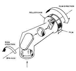
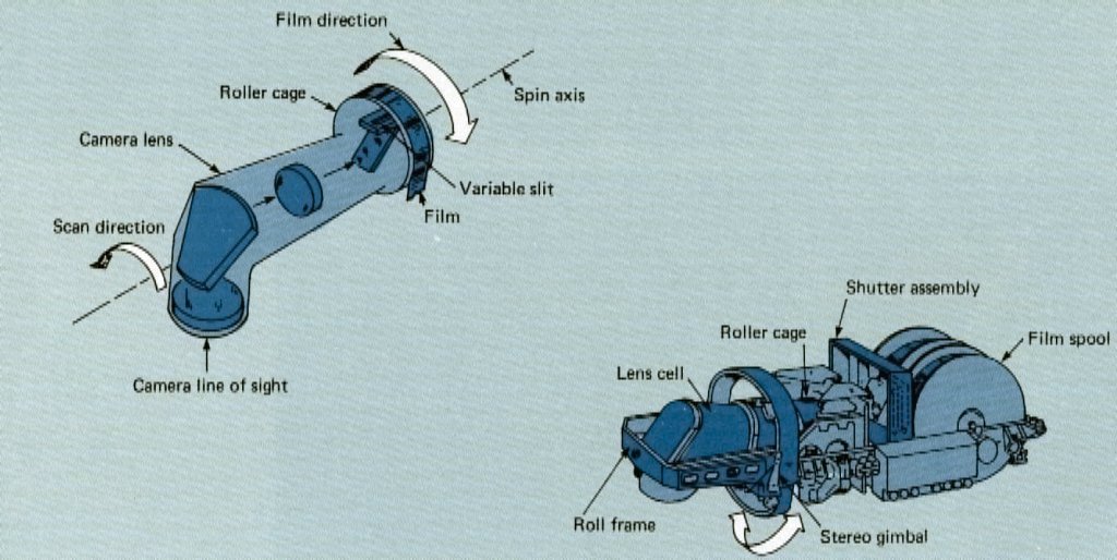
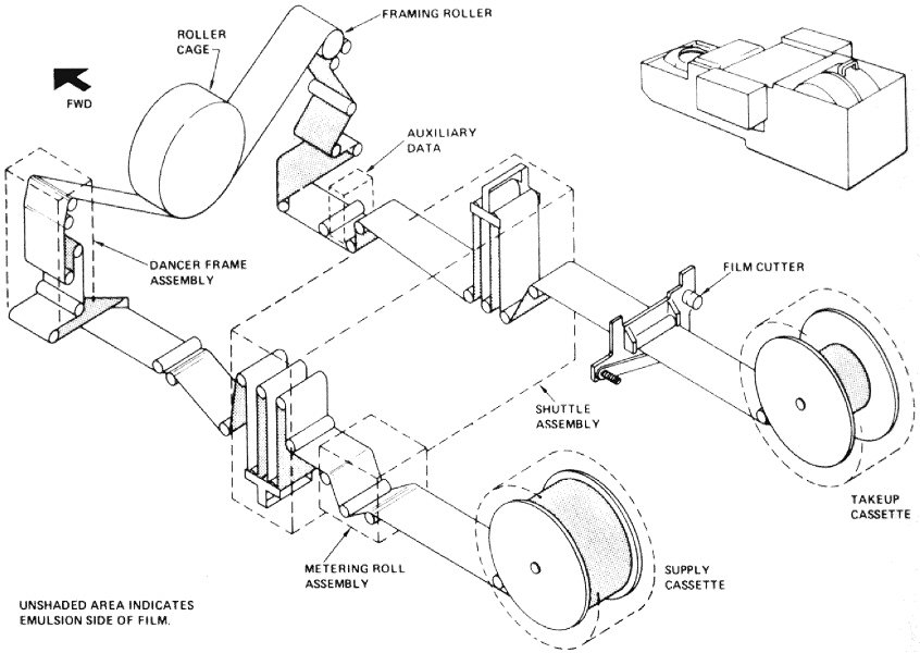
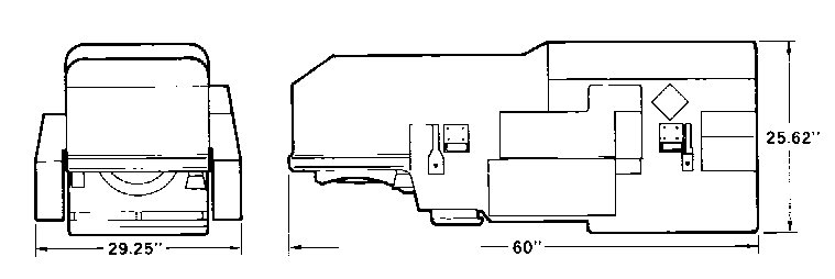
The lens is formed in the shape of an elongated N (see diagram above), the optical path being bent by two folding mirrors located at the pivot points of the N. This provides for the longest possible focal length consistent with the size of the camera compartment.
In addition to receiving operating and temperature control power from the Apollo Service Module, the camera is connected to the vehicle telemetry circuits, to the experiment equipment control panel in the Apollo Command Module, and to the vehicle central timing equipment.
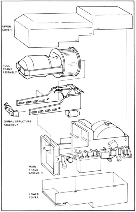
The camera comprises three major assemblies: (1) the roll frame assembly, which basically provides the platform for the rotating lens system, (2) the gimbal structure assembly, which rocks the roll frame assembly back and forth to provide for the stereo photography and to compensate for the forward motion of the vehicle, and (3) the main frame assembly, which attaches to the vehicle and provides a platform for the film transport system as well as the roll frame and gimbal structure assemblies.
Click to enlarge.
Click to enlarge.
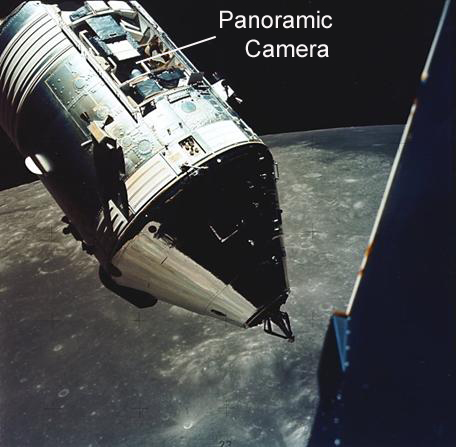
Panoramic camera as seen from the Apollo 17 Lunar Module Challenger.
During the operation of the camera, the lens is rotated about an axis which is parallel to the Apollo Command Module at a rate related to the apparent ground speed. A capping shutter opens during the time the lens passes through a 108° arc below the vehicle.
Light entering the lens during this scan period is focused onto the film through a variable width slit located at the rear of the lens system next to the film. The slit is continuously variable (governed by signals from a light sensor and V/H sensor) from a minimum opening of 0.015 inch (0.381 mm) to a maximum opening of 0.300 inch (7.62 mm). The width of the scanning slit at any particular time combined with the scanning rate (the rate of rotation of the lens) establishes the photographic exposure time.
Click to enlarge.
Click to enlarge.
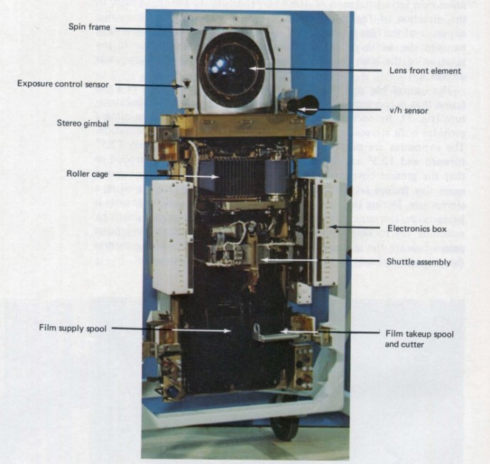
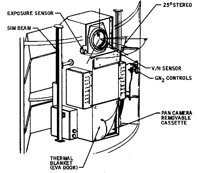
Pan camera in the SIM bay.
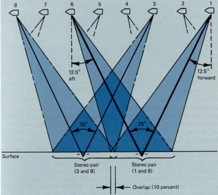
When the camera operates in the stereo mode, the gimbal structure automatically pitches alternately from a position 12.5° forward to 12.5° aft of the vertical between successive exposures. That is, one exposure will begin with the gimbal structure in a position 12.5° forward of vertical, the next exposure will begin with the structure at a position 12.5° aft of vertical, and for the next it will shift to the 12.5° forward position once again. The cycle rate of the camera is set so that a 100 percent overlap between stereo pairs is maintained. When properly viewed, the two photographs of the same ground area thus taken from different angles provide a 25-degree convergent stereo image (see diagram below).
Click to enlarge.
Click to enlarge.
A velocity to height ratio (V/H) sensor and an incremental shaft angle encoder control the camera operating cycle. The V/H sensor continuously determines the rate of apparent motion of the ground scene, and controls both the motion of the gimbal structure for forward motion compensation and the speed of the rotation of the lens system (the optical bar). The speed of the film across the roller cage is, in turn, controlled by the rotation of the optical bar. A light sensor determines the degree of the ground brightness. This information is combined with the information from the V/h sensor in the exposure control assembly, which adjusts the film. The incremental shaft angle encoder, in combination with a cycle control assembly, provides the timing and synchronization for the operating subsystems of the camera.
The film metering roller continuously moves film from the supply cassette to a supply shuttle (a system of fixed and suspended rollers which stores a surplus of film ready for use). At a rate synchronized with the cycle rate, a framing roller intermittently draws film across the revolving roller cage in the direction opposite to that of the lens rotation, through the focal plane, and then into a take-up shuttle. The supply shuttle is refilled during that portion of the cycle when the film remains stationary over the roll cage. Film in the take-up shuttle is continuously drawn into the take-up cassette. It takes approximately 2 seconds for each complete exposure during which time 1.2m of film is passed over the roller cage and past the exposure slit. Consecutive frames were exposed every 6 seconds. The surplus film which is intermittently entering and leaving the supply and take-up shuttles provides the flexibility required to maintain constant film tension throughout the system while the gimbal assembly tilts through its stereo and forward motion compensation cycle.
Because the camera lens rotates at a distance from the image surface (the radius of the roller cage) which is not equal to the focal length of the lens, lateral image motions could be introduced. During the exposure cycle, the film is moved across the roller cage in a direction opposite to the lens rotation to compensate for these image motions. The rate of film transport is proportional to the rotation rate of the lens.
Click to enlarge.
The film take-up cassette is removed from the camera by an astronaut during an extravehicular activity (EVA) and stored aboard the Apollo Command Module for return to Earth.
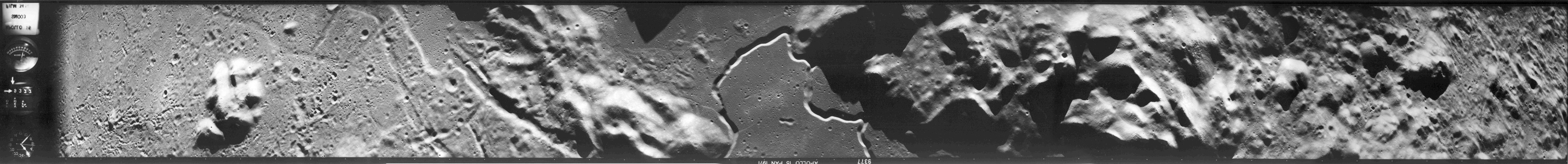
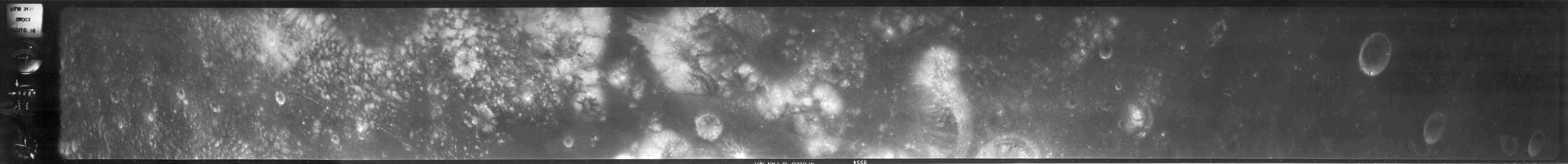
Below are examples of the photography produced by the panoramic camera.
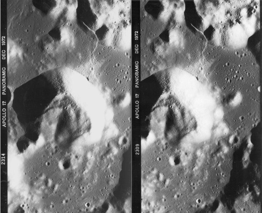
Below is the centre segment from the panoramic frames AS17-2309 & AS17-2314 of the valley of Taurus-Littrow. They represent a 25° convergent stereoscopic pair.
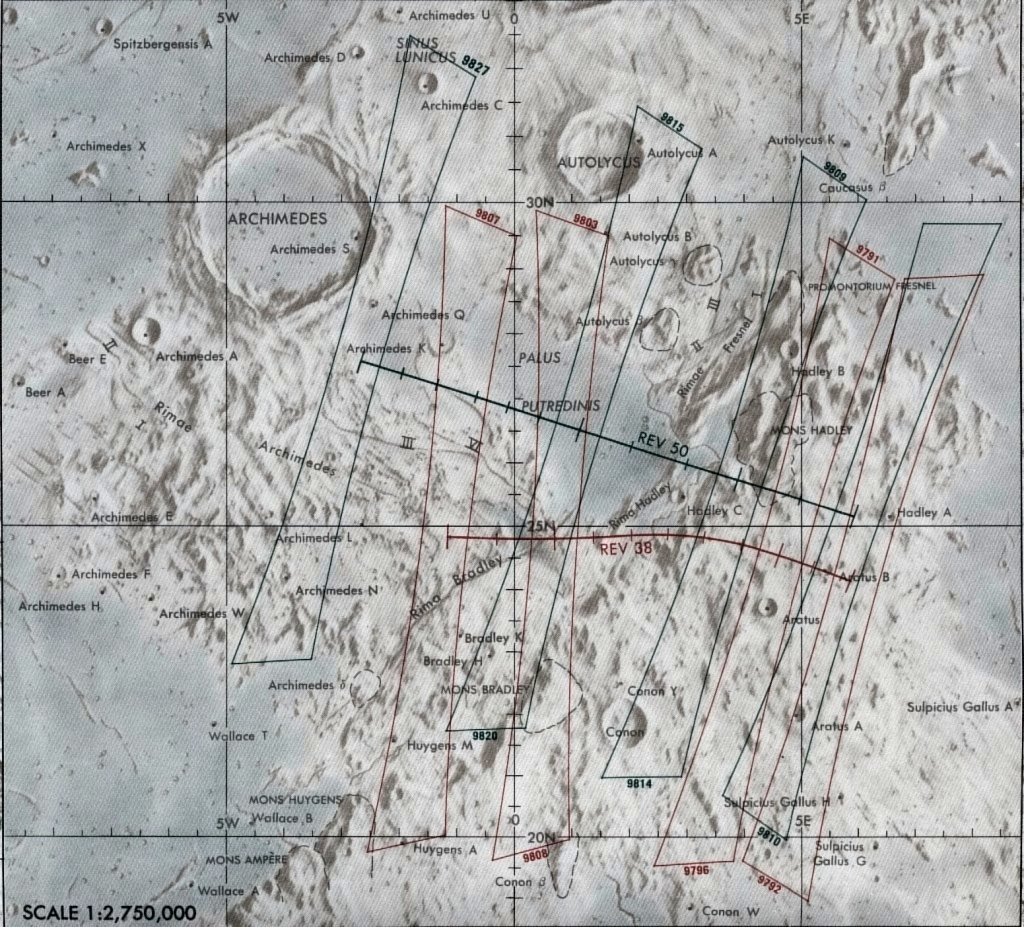
Below are examples of the topographic mapping products that were produced using imagery from the panoramic camera.
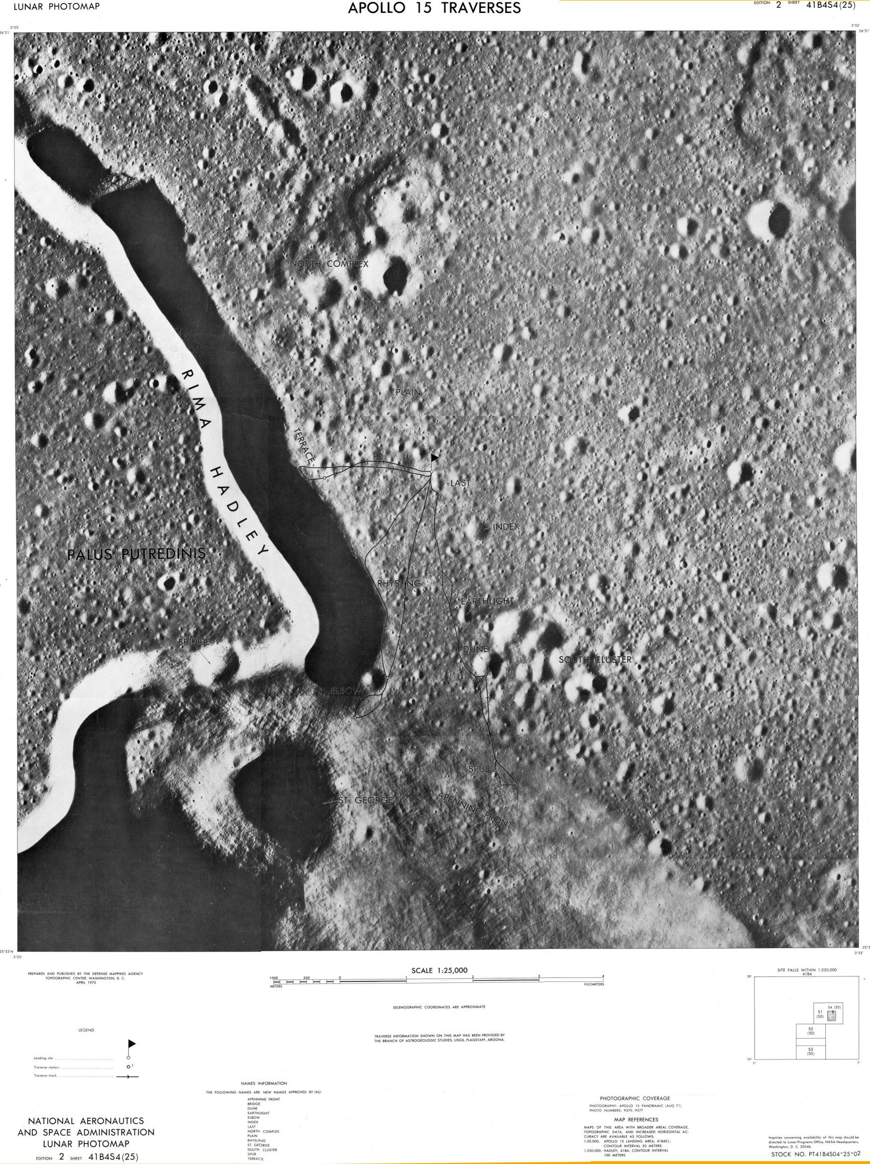
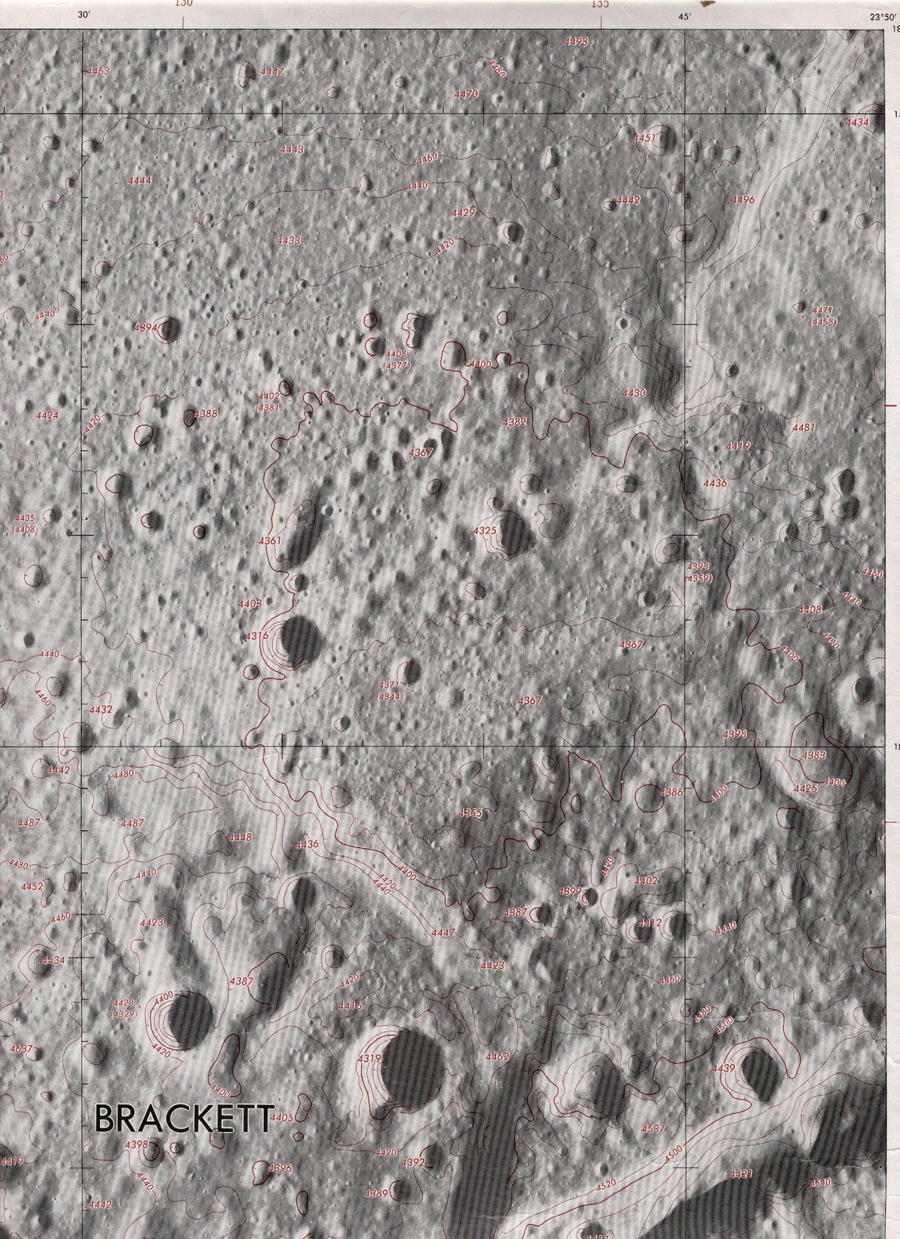
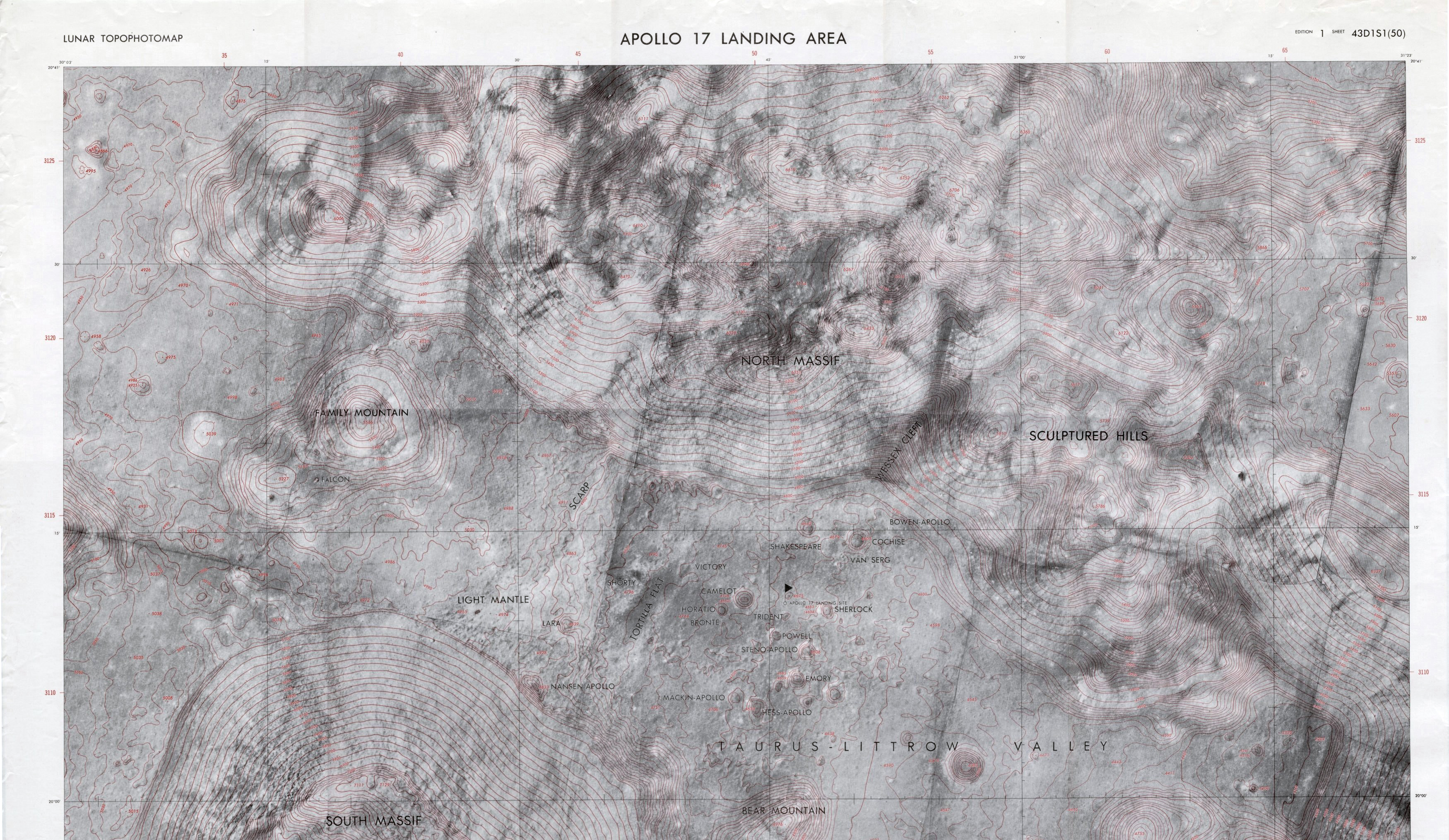
Click the above maps to enlarge.
These maps were produced for NASA by the Defense Mapping Agency, Topographic Center, Washington, D.C.
Copies of the photographs taken by the Panoramic Camera and maps derived from it's imagery can be obtained from the National Space Science Data Center at http://nssdc.gsfc.nasa.gov/
| Lens | 24-inch (610-mm), f/3.5, Petzval |
| Resolution | 135 lines per millimetre, over 80 percent of the detail, no detail less than 108 lines per millimetre at low contrast |
| Field of view along track | 10 degrees 46 minutes (13.5 miles at 69-mile altitude) |
| Field of view, crosstrack | 108 degrees (211 miles at 69-mile altitude) |
| Overlap | Consecutive forward frames and consecutive aft frames overlap 10 percent; stereo pairs overlap 100 percent. |
| Shutter type | Scanning slit |
| Slit width | 0.015 to 0.300 inch (0.381 to 7.62 mm) |
| Film type | 3400, 3414, SO-230, or any other thin base material. |
| Film width | 5 inches (127 mm) |
| Film thickness | 0.003 inch (0.076 mm) or less. |
| Format | 45.24 by 4.5 inches (1,149 x 114.3 mm) |
| Exposure control | Automatic with variable slit |
| V/H Range | 0.010 to 0.019 radians per second |
| Operating modes | Monographic or 25° convergent stereo at autocyle of 4.7 to 8.0 seconds per cycle. |
| Film Length | 6,500 feet (2,005 metres) |
| Exposures | 1,650 total |
| Weight (camera with film) | 336 pounds |
| Weight (Take-up cassette with film) | 73 pounds |
| Power Requirements | 115VAC, 27.5VDC, 234 watts average, 340 watts peak |
Apollo 15 CM Software - Delco Electronics, 1971
Apollo 15 Press Kit - NASA 71-119K, July 1971
Apollo 15 Mission Report - NASA MSC-05161, December 1971
On the Moon with Apollo 16, Gene Simmons - NASA EP-95, 1972
On the Moon with Apollo 17, Gene Simmons - NASA EP-101, 1972
Apollo over the Moon, Harold Masursky, G. W. Colton, Farouk El-Baz - NASA SP-362, 1978
North American Rockwell - Space Division, Fact Sheet SP-29, 1972
Chariots for Apollo: A History of Manned Lunar Spacecraft. C. G. Brooks, J. M. Grimwood, L. S. Swenson jnr - NASA SP-4205, 1979
Where No Man Has Gone Before: A History of Apollo Lunar Exploration Missions. William Crompton - NASA SP-4214, 1989
National Space Science Data Center

|
|
|
|
|
The Fairchild Lunar Mapping Camera |
Return to SIM Bay Cameras |
Apollo 17 Photographic Task Requirements |