
Note: The functional description of each of the four major ECS sections is supported by a functional flow diagram, which, to reduce complexity, does not contain electrical circuitry.
Note: The functional description of each of the four major ECS sections is supported by a functional flow diagram, which, to reduce complexity, does not contain electrical circuitry.
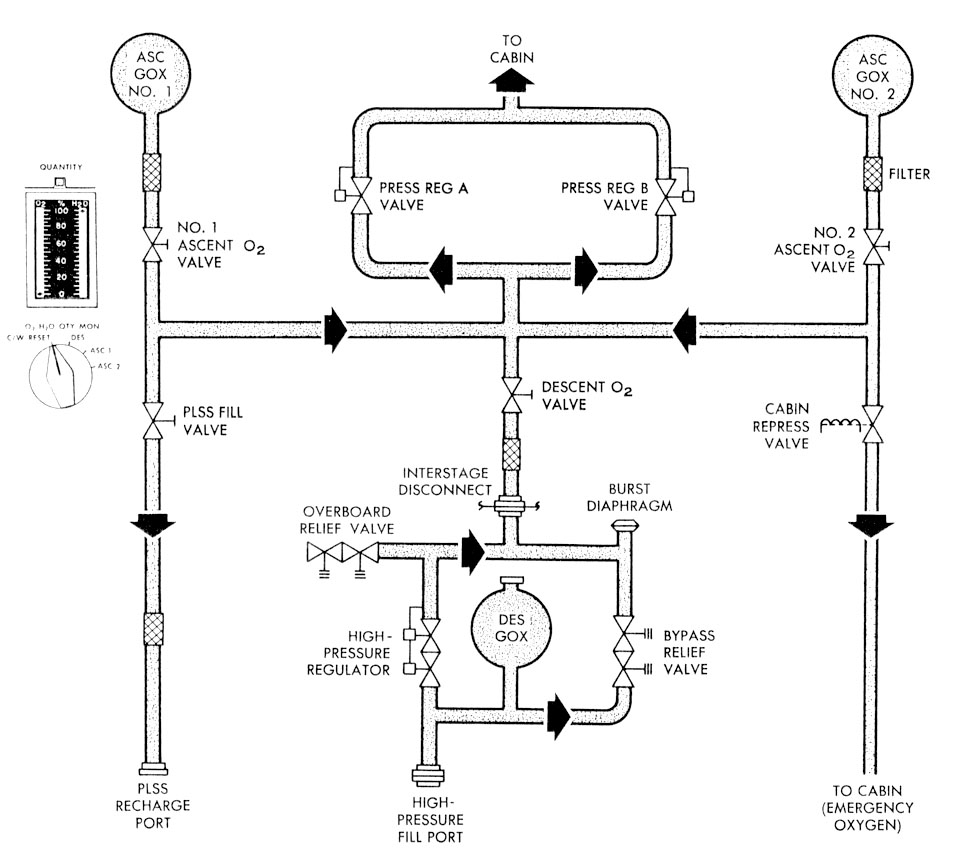
The OSCPCS stores gaseous oxygen, replenishes the ARS oxygen, and provides refills for the PLSS oxygen tank. Before staging, oxygen is supplied from the descent stage oxygen tank. After staging, or if the descent tank is depleted, the ascent stage oxygen tanks supply oxygen to the oxygen control module. The high-pressure assembly in the descent stage, and the oxygen control module in the ascent stage, contain the valves and regulators necessary to control oxygen in the OSCPCS. The cabin relief and dump valves ( 109k) vent excess cabin pressure.
A high-pressure regulator reduces descent tank pressure, approximately 2,730 psia, to a level that is compatible with the components of the oxygen control module, approximately 900 psig. A series redundant overboard relief valve protects the oxygen control module against excessive pressure caused by a defective regulator or by flow through the bypass relief valve. If the pressure on the outlet side of the regulator rises to a dangerous level, the burst diaphragm assembly vents the high-pressure assembly to ambient. A poppet in the burst diaphragm assembly reseats when pressure in the high-pressure assembly is reduced to approximately 1,000 psig. Descent oxygen flow through the interstage disconnect to the oxygen control module is controlled with the descent oxygen shutoff valve ( 164k). The interstage disconnect acts as a redundant seal to prevent loss of oxygen overboard after staging.
When ascent stage oxygen is required, the ascent oxygen shutoff valves ( 164k) are used to select their respective tank. A mechanical interlock prevents the valves from being opened unless the descent oxygen shutoff valve ( 164k) is closed. The mechanical interlock may be overridden (if the descent oxygen shutoff valve cannot be closed and the ascent oxygen shutoff valves must be opened) by pressing the interlock override push button on the oxygen control module ( 164k).
From the oxygen shutoff valves, oxygen is routed to oxygen demand regulators, a PLSS fill valve, and a cabin repressurization and emergency oxygen valve. The PLSS fill valve connects the PLSS oxygen tank through a flexible service hose. A check valve in the PLSS disconnect is opened when the hose is connected. The valve automatically closes when the hose is disconnected. The oxygen demand regulators maintain the pressure of the suit circuit at a level consistent with normal requirements. Both regulators are manually controlled ( 164k) with a four-position handle; both are ordinarily set to the same position. The CABIN position is selected during normal pressurized-cabin operations, to provide oxygen at 4.8±0.2 psia. Setting the regulators to the EGRESS position maintains suit circuit pressure at 3.8±0.2 psia. The DIRECT 02 position provides an unregulated flow of oxygen into the suit circuit. The CLOSE position shuts off all flow through the regulator. In the CABIN and EGRESS positions, the regulator is internally modulated by a reference pressure from the suit circuit. The demand regulators are redundant; either one can fulfill the ARS oxygen requirements.
If both demand regulators are set to the CABIN or DIRECT 02 position and cabin pressure drops to 3.7 to 4_45 psia, the cabin pressure switch energizes the cabin repressurization valve ( 164k) and oxygen flows through the valve into the cabin. If cabin pressure builds up to 4.45 to 5.0 psia, the cabin pressure switch de-energizes the valve solenoid, shutting off the oxygen flow. The valve can maintain cabin pressure at 3.5 psia for at least 2 minutes following a 5.0-inch-diameter puncture of the cabin. It responds to signals from the cabin pressure switch during pressurized-cabin operation and to a suit circuit pressure switch during unpressurized operation. Manual override capabilities are provided.
Both cabin relief and dump valves ( 109k) (one in the forward hatch, the other in the overhead hatch) are manually and pneumatically operated. They prevent excessive cabin pressure and permit deliberate cabin depressurization. The valves automatically relieve cabin pressure when the cabin-to-ambient differential reaches 5.4 to 5.8 psid. When set to the automatic (AUTO) position, the valves can be manually opened with their external handle. The valve in the overhead hatch can dump cabin pressure from 5.0 to 0.08 psia in 180 seconds without cabin inflow. The valve in the forward hatch requires 310 seconds to dump the same amount of cabin pressure because of the flow restriction caused by the bacteria filter (used only on Apollo 11). In addition to relieving positive pressure, the valves relieve a negative cabin pressure condition.
To egress from the LM, (1) the oxygen demand regulators ( 164k) are set to the EGRESS position, turning off the cabin fans, and closing the suit gas diverter valve; (2) the cabin gas return valve ( 159k) is set to the EGRESS position; and (3) cabin pressure is dumped by opening the cabin relief and dump valve ( 109k). A bacteria filter (flown only on Apollo 11) on the cabin side of the cabin relief and dump valve in the forward hatch removes 95% of all bacteria larger than 0.5 micron from the dumped oxygen. When repressurizing the cabin, the cabin relief and dump valve ( 109k) is set to the automatic (AUTO position, the oxygen demand regulator valves ( 164k) are set to the CABIN position, and the cabin gas return valve is set to the automatic (AUTO) position. The cabin warning light goes on when the regulators are set to the CABIN position and goes off when cabin pressure reaches the actuation pressure of the cabin pressure switch.