
Additional information on LRV deployment is available in the Lunar Roving Vehicle Operations Handbook, Boeing document LS006-002-2H. Figures 1-37 and 38 in that document show the attachment and deployment hardware. Figure 1-39 is a cartoon of the deployment sequence. Section 1.9.3 of the document contains a complete description of the deployment.
In the Grumman cartoons that follow, the rugged terrain, stars, and mottled sky all result from unrestrained use of artistic "licence". Sigh.
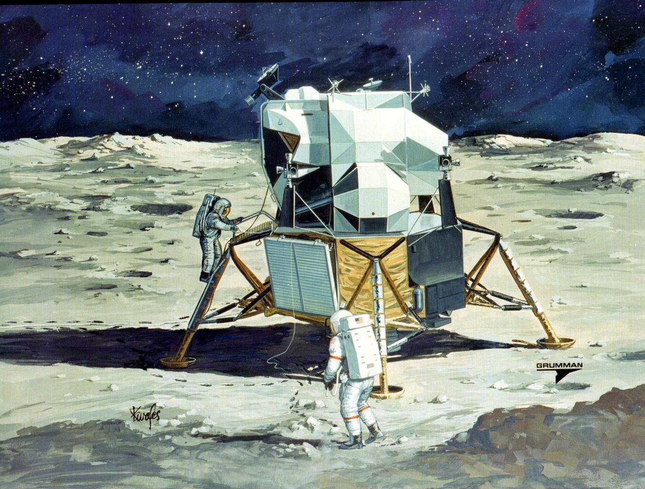
The LMP is on the ladder (left) having just pulled the D-ring to release the Rover package. Click on the image for a larger version.
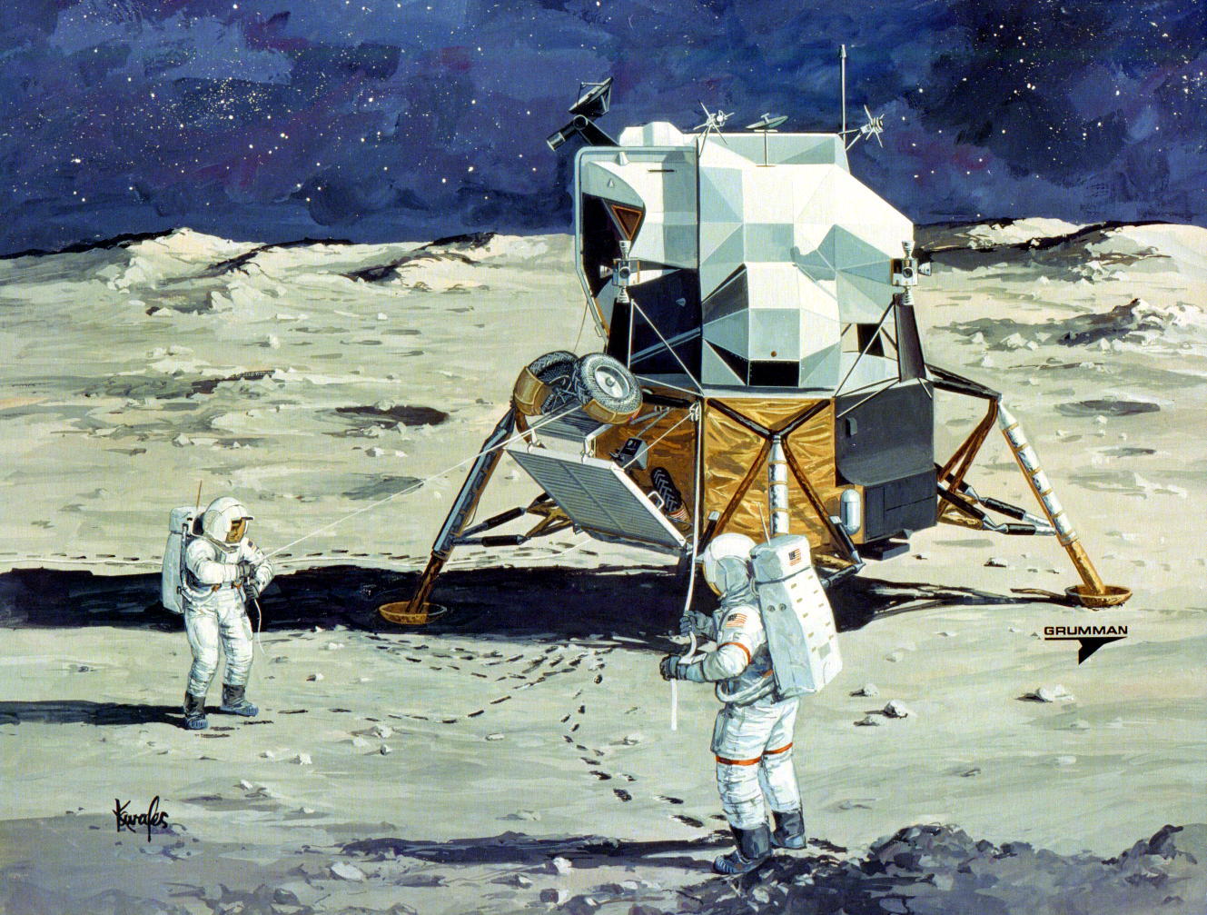
The LMP (left) keeps a lanyard in tension while the CDR (red arm and leg bands) pulls out the wheel-wound, righthand tape to drive the semi-automatic deployment sequence. A combination of gravity, springs, carefully placed mechanical supports, and a judicious tug or two on the lanyard by the LMP will lead to the various parts of the Rover snapping into place in the proper sequence as the CDR pulls out the righthand tape. Here, the aft portion of the Rover chassis and the aft wheels are about to snap into positon. Click on the image for a larger version.
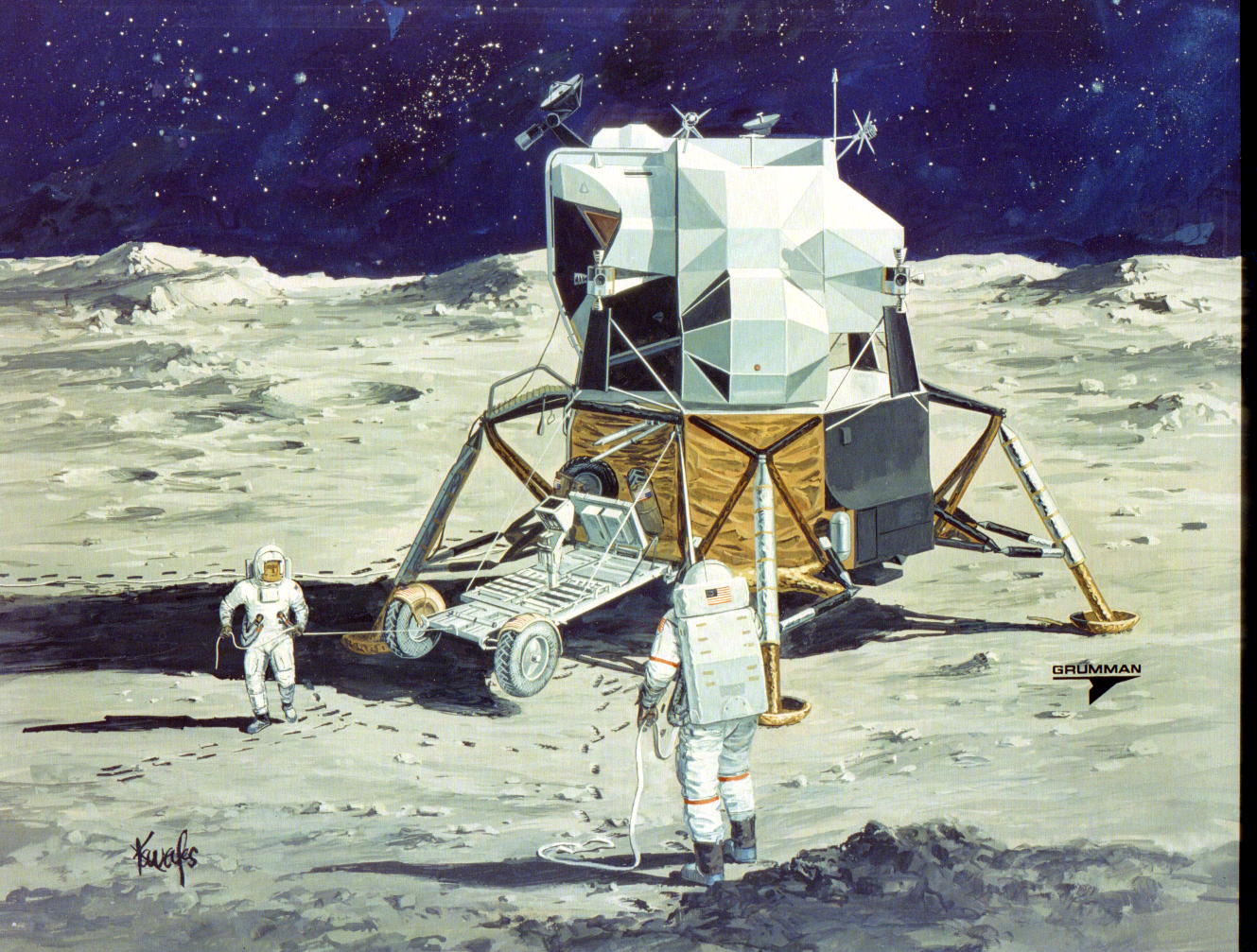
The forward chassis section and wheels are about to snap into positon. Click on the image for a larger version.
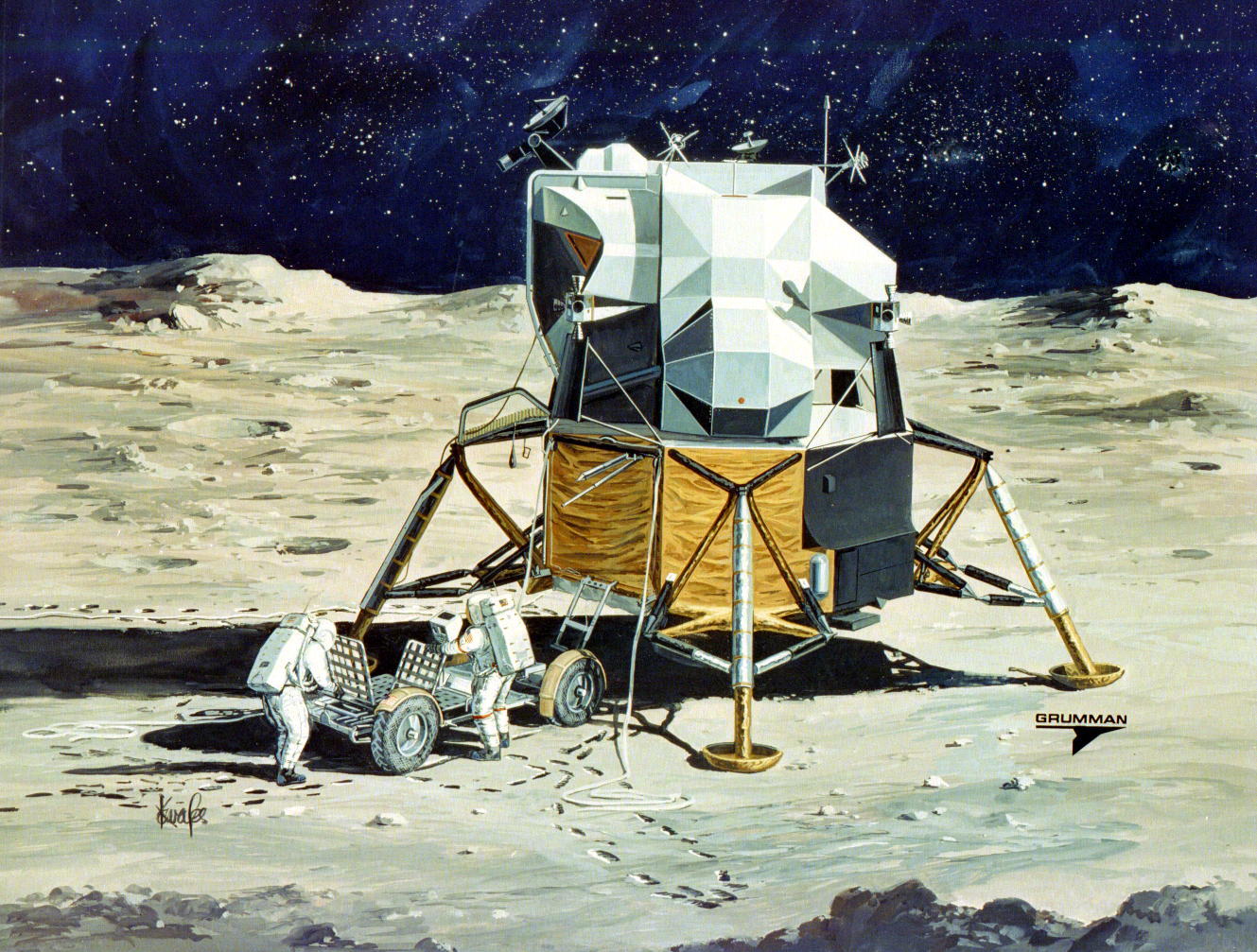
The LMP (left) and CDR raise their Rover seatbacks. Click on the image for a larger version.
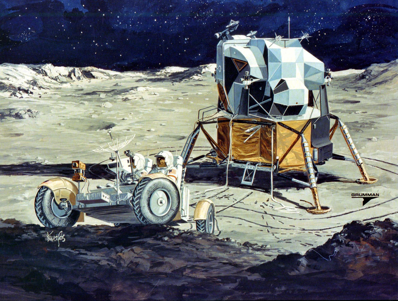
The crew departs on a hypothetical geology traverse. The CDR is in the near seat. No crew would have landed anywhere near so dramatic a rocky outcrop nor have driven on one. Click on the image for a larger version.