
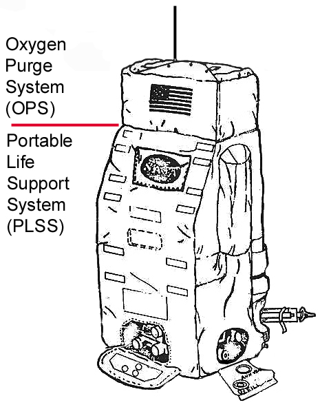
Apollo Oxygen Purge System (OPS)
for the Portable Life
Support System (PLSS)
& Extravehicular
Mobility Unit (EMU)
By Karl Dodenhoff
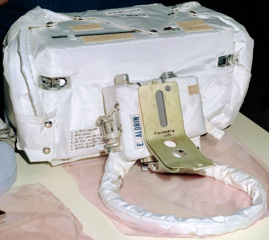
Above: NASA photo S69-38496
Apollo OPS unit used by Edwin Aldrin on Apollo
11. In front of the OPS is the RCU.
These two units, along with the PLSS, comprised the life support system
used on all of the Apollo program lunar surface EVAs.
Description
From: CSD-A-789-(1) REV V
Apollo Operations Handbook Extravehicular Mobility Unit, March 1971
Volume 1 – System Description
Pages 2-106 thru 2-110
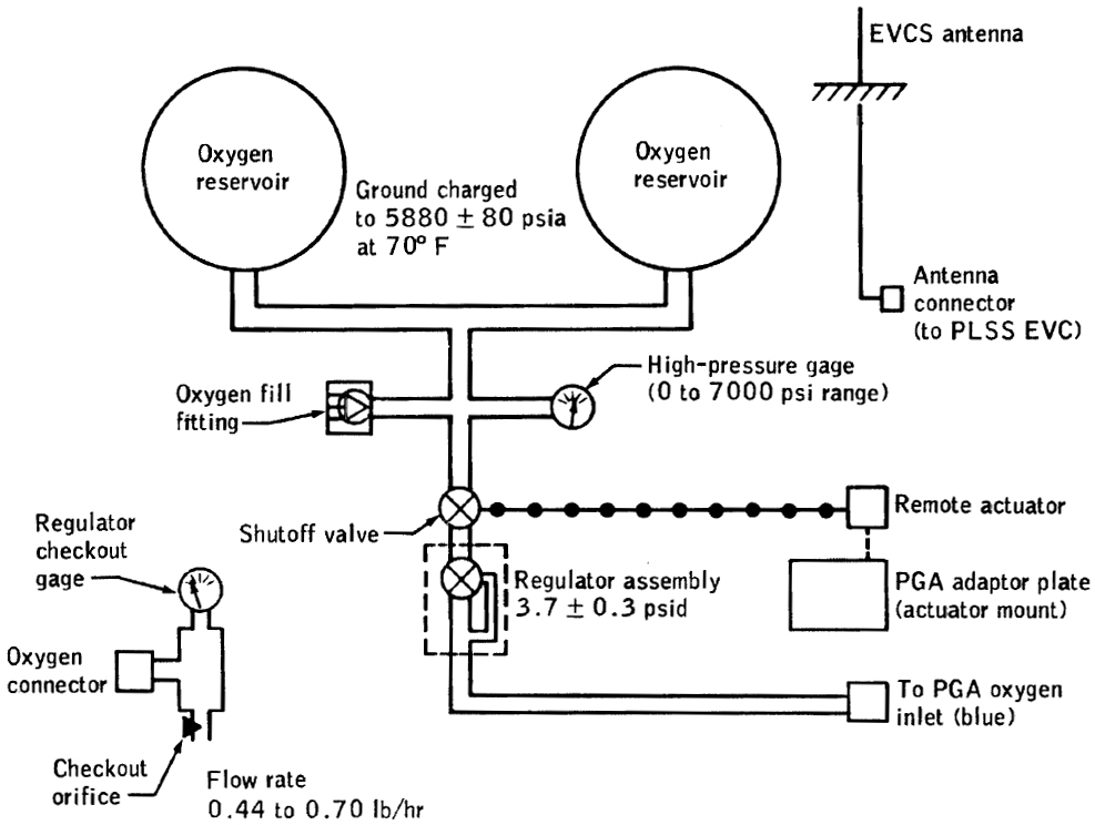
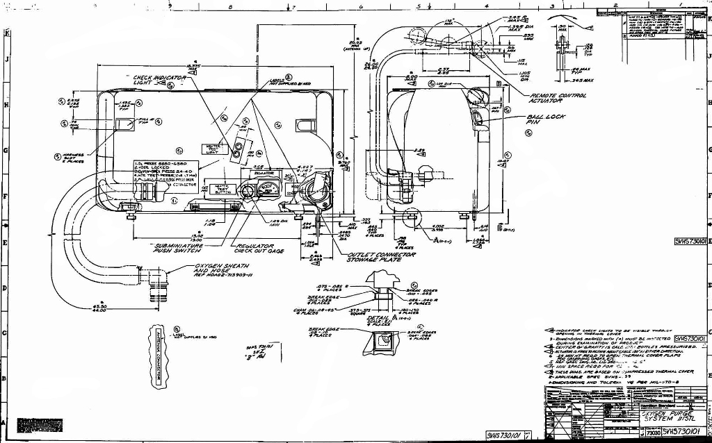
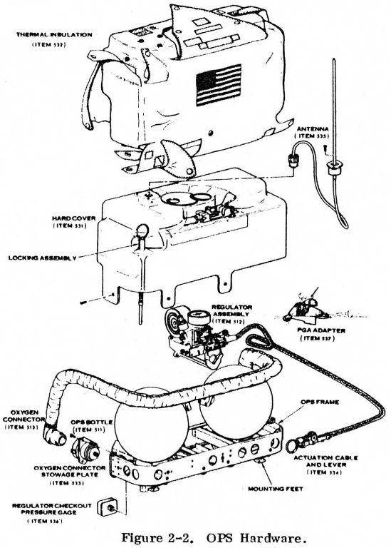
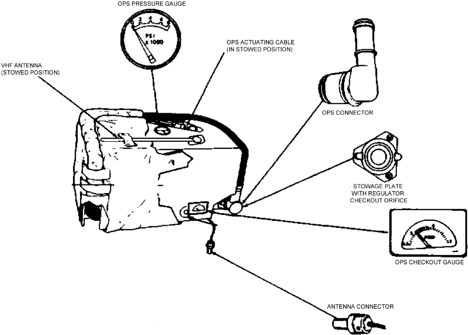
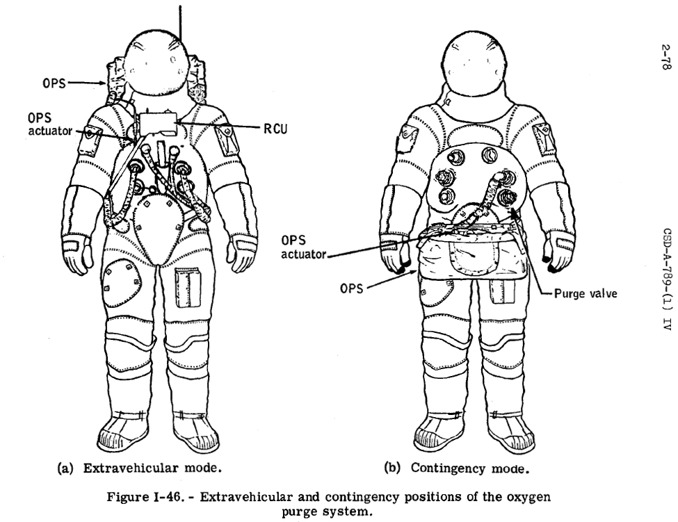
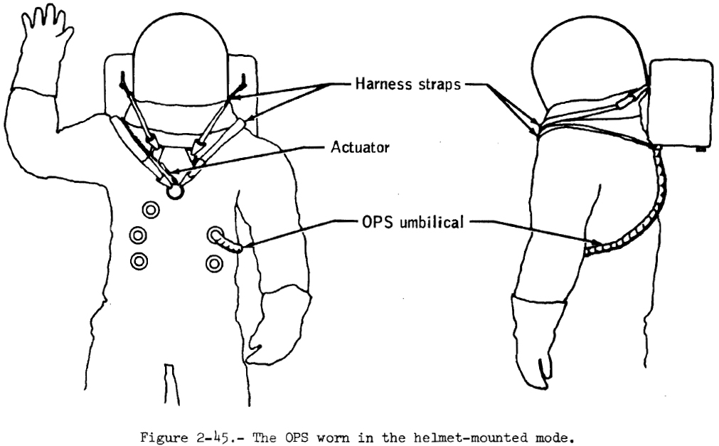
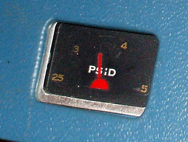
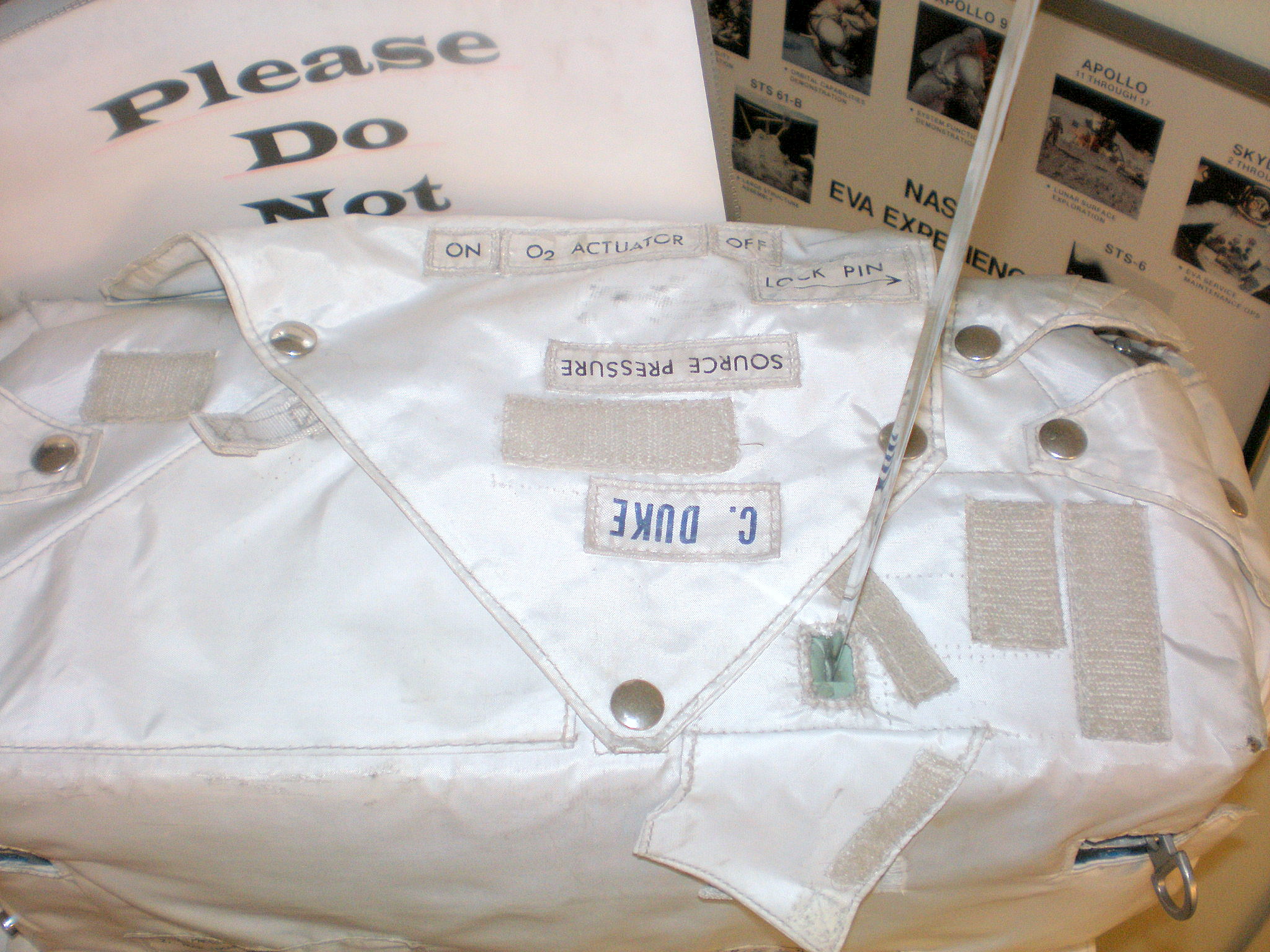
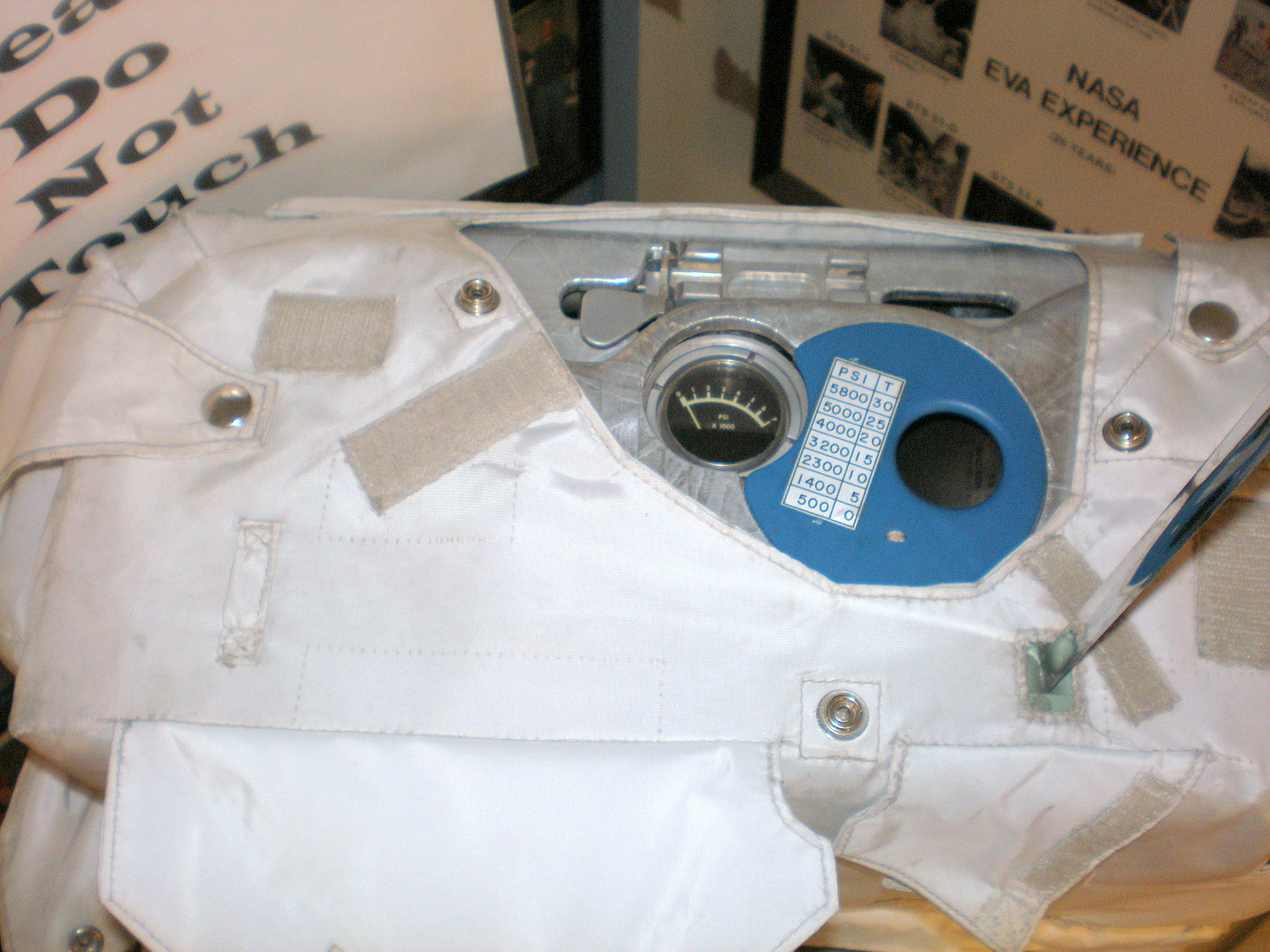
The OPS (fig. 2-44, below) supplies the EMU with oxygen purge flow and pressure control for certain failure modes of the PLSS or PGA during EVA. In the event of a PLSS failure, the OPS flow is regulated to 3.7 +/- 0.3 psid for 30 minutes to provide breathing oxygen to the crewman, to prevent excessive carbon dioxide buildup, and to provide limited cooling. In this mode, the crewman sets his purge valve in the high-flow position (8.1 pounds per hour). In a second mode, the OPS may be used to provide make-up flow to the PLSS oxygen ventilating circuit via the PGA at flow rates of 0.07 to 2.0 pounds per hour. Finally, the OPS can be used in conjunction with the BSLSS to provide a 1.25-hour supply of purge flow for a crewman with a failed PLSS. For this mode, the crewman sets his purge valve in the low-flow position (4.0 Ib of 02 per hour). In the lunar EVA configuration, the OPS is mounted on top of the PLSS. For normal EV activity from the command module, the OPS is worn in the helmet-mounted mode as shown in figure 2-45. During contingency EV transfer from the lunar module, however, the OPS is attached by straps to the lower front torso of the PGA (figure 1-46).
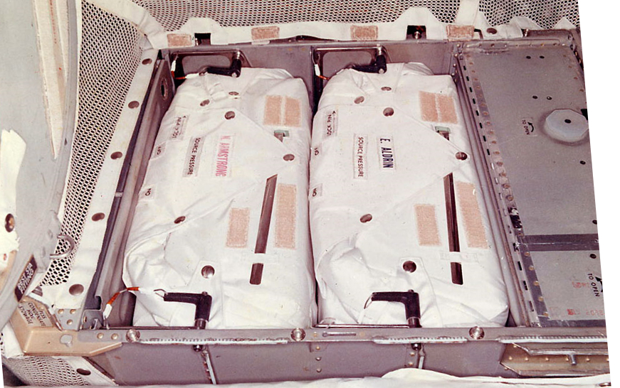
The 2 OPS for Apollo 11 stowed inside Eagle
Note stowed antennae and crewmen's name tags
(CDR in RED, LMP in black)
A schematic representation of the OPS is shown in
figure 2-47. The OPS consists of two
interconnected, spherical, high pressure oxygen bottles (total
of 5°1 pounds of usable oxygen at 5880 +/- 80 psia and 70
° F), a pressure regulator assembly, a fill fitting, a
high-pressure gage, a delta-pressure gage, a suit connector and
hose, a suit connector stowage plate, a shutoff valve, and an
actuator cable and handle. The OPS has no communications
capability, but provides the hard mount for the PLSS antenna.
The OPS used for Apollo 15 and subsequent missions differs from
the OPS used on Apollo 14 in that attachment points for the PLSS
harnesses have been moved to permit helmet mounting. Also the
oxygen outlet temperature control capability incorporated in the
OPS for all missions through Apollo 13 has been deleted. Thus
the heater, control
circuitry, terminal board, temperature sensor,
power switch, and battery have been removed, as shown in figure 2-2. The OPS is not rechargeable
during a mission. The high pressure gage is used to monitor
bottle pressure during ground charge and during preoperational
checkout.
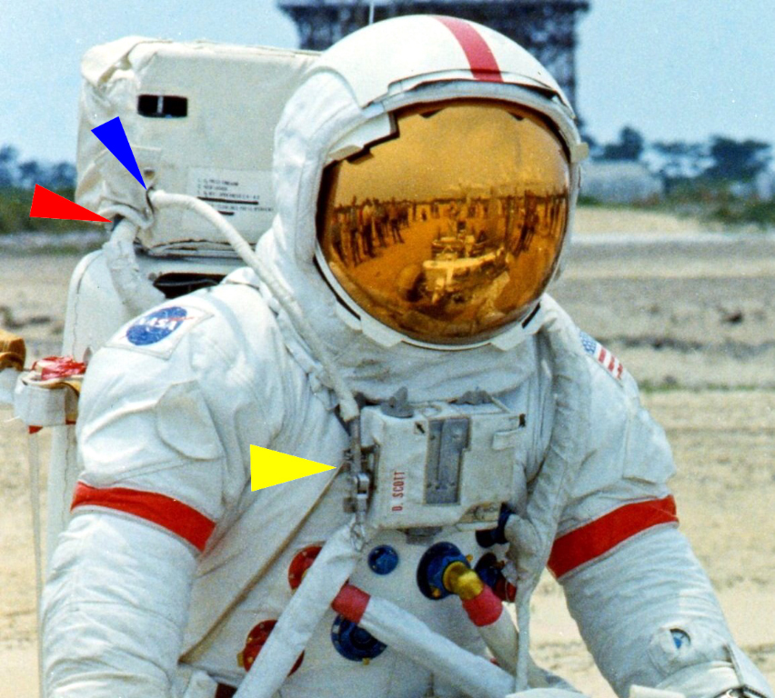
Detail from NASA photo 71-HC-731
The blue arrow shows the OPS Actuator cable
The red arrow shows the Oxygen Umbilical
The yellow arrow shows the OPS
Actuator
attached to the side of the RCU
Diagrams


by David Jackson
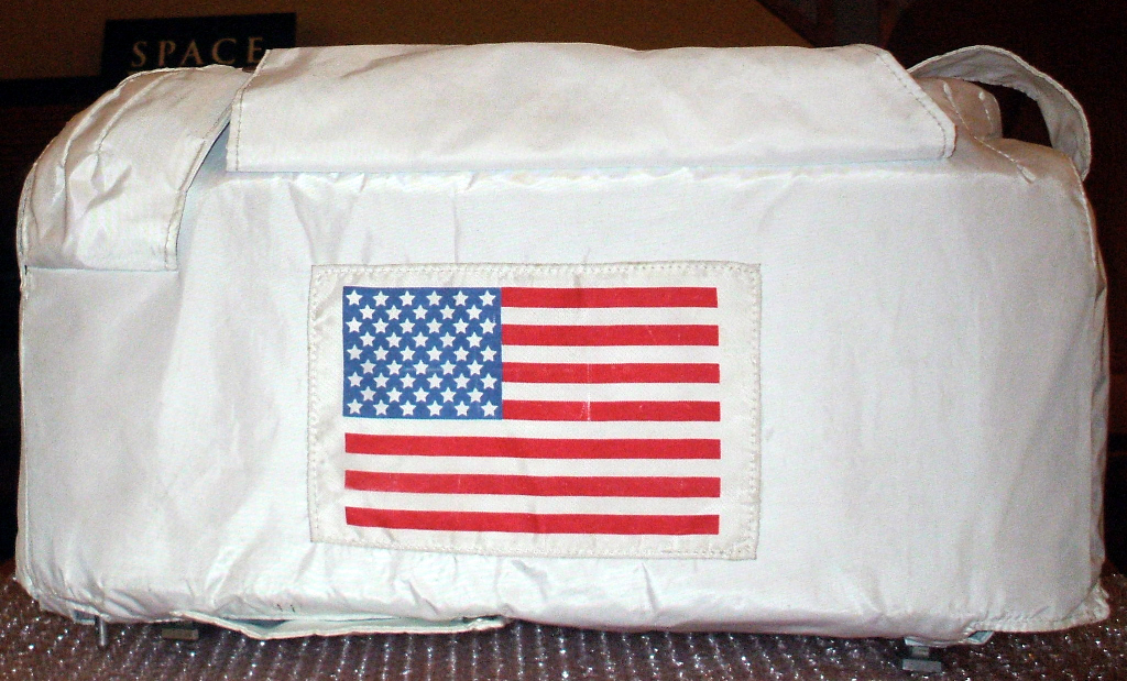 |
Probably the "familiar face" of the OPS to most people, as seen in so many lunar EVA photographs. This is the "back", the side facing away from the crewmen, with the white Beta cloth thermal covering |
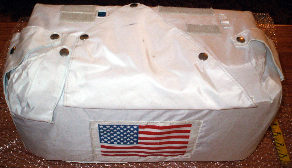 |
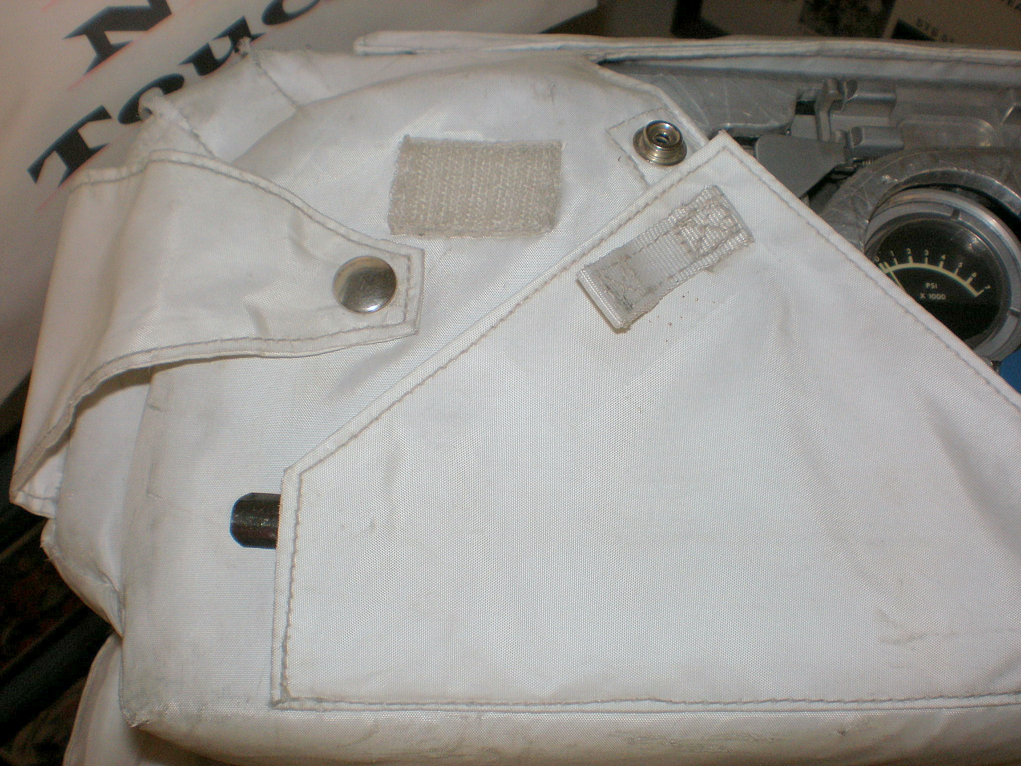
Top face of the OPS, from the rear. Note the various flaps. The triangular flap was most often photographed open. It was used to cover the OPS Pressure Gage and to help keep the antenna folded down when it was stowed. This OPS came with no antenna or tags on the thermal cover. Compare to photo above |
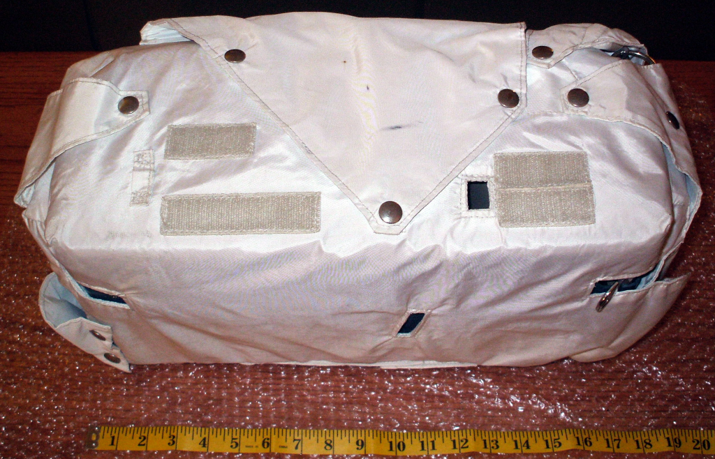 |
Top face of the OPS, from the front - the side facing the crewmen. Note the velcro patches, and the small, vertical opening in the thermal cover right of center on the front face. This is where the Heater Test Light was located on the G and H-Series OPS. Compare to photo of the stowed A11 OPSs |
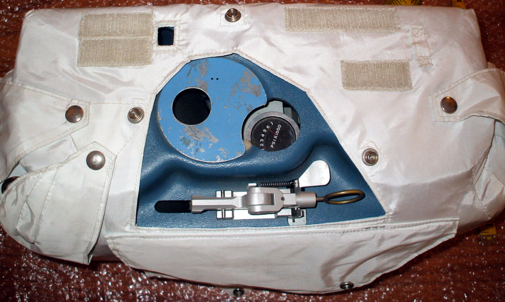 |
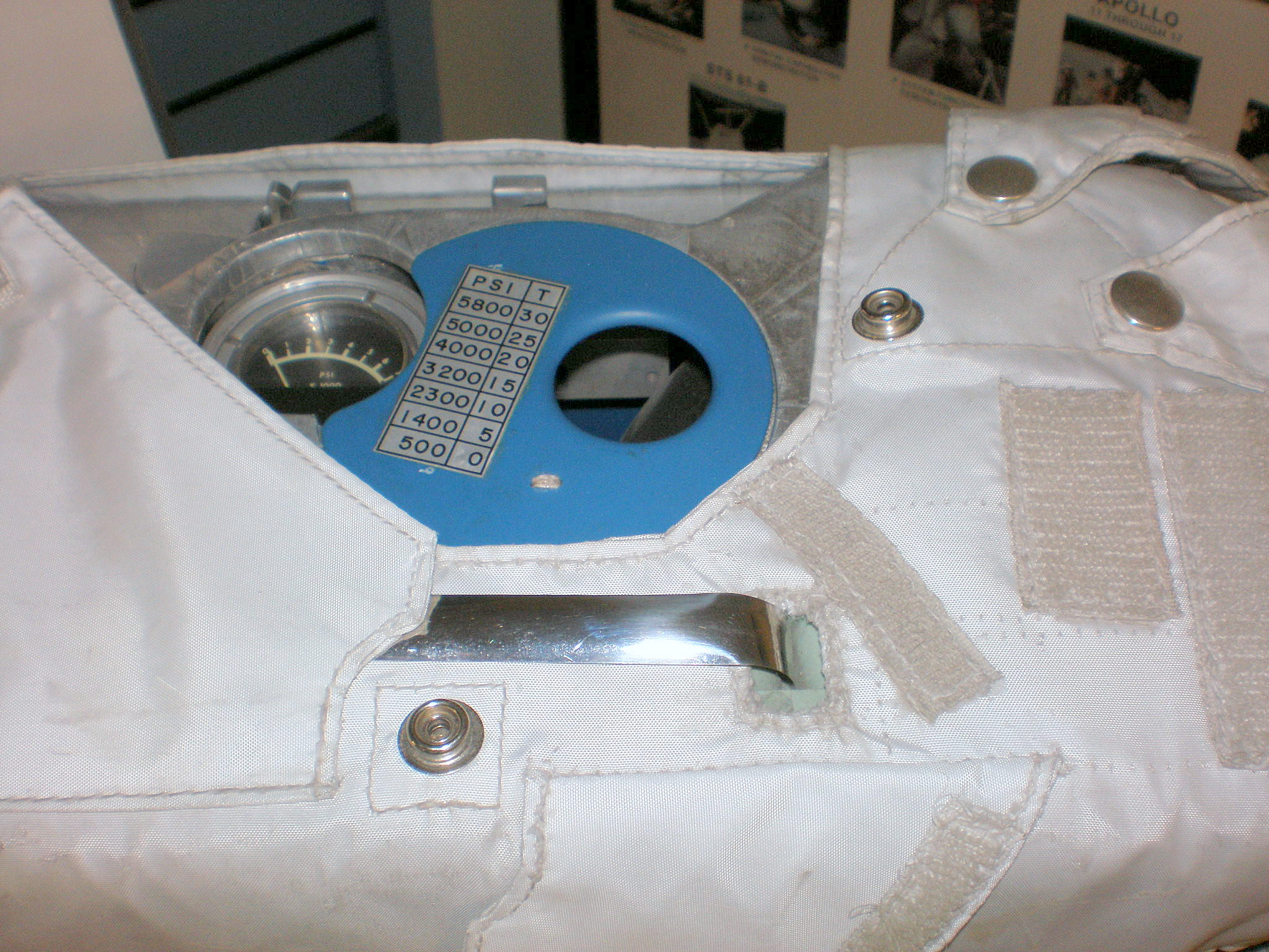
Excellent photo showing the top face of the OPS, from the rear, with the triangular flap open to reveal the OPS Pressure Gage and Actuator in it's stowed configuration. |
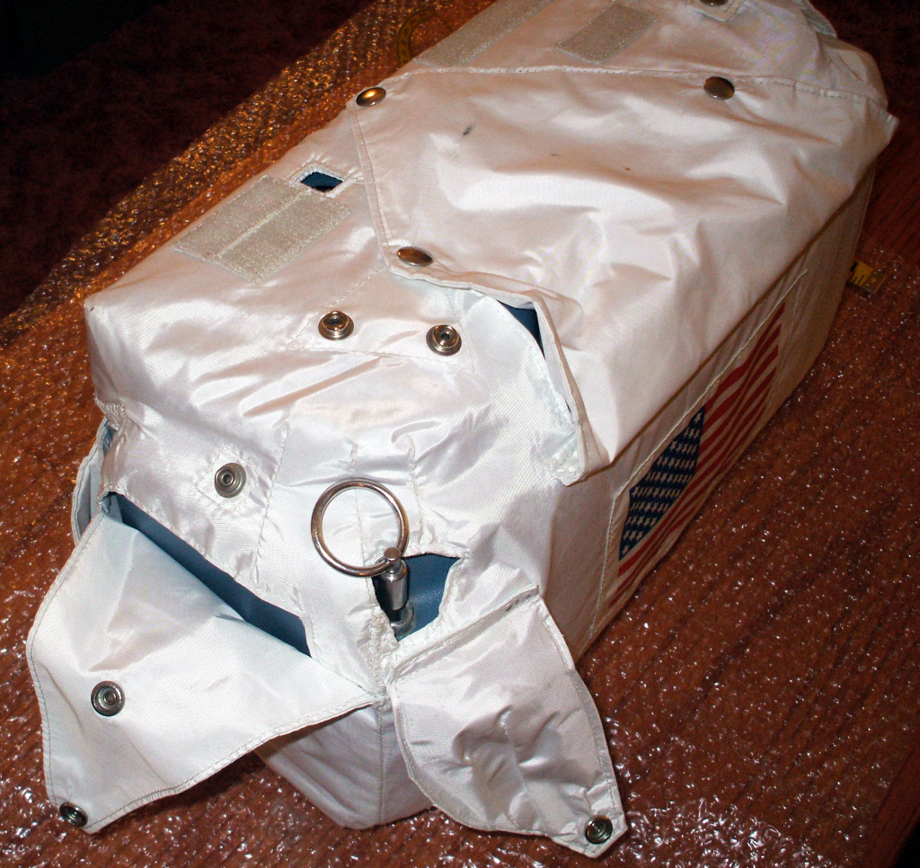 |
Three quarter view from the rear, showing the round Locking Pin that anchored the OPS firmly to the top of the PLSS |
 |
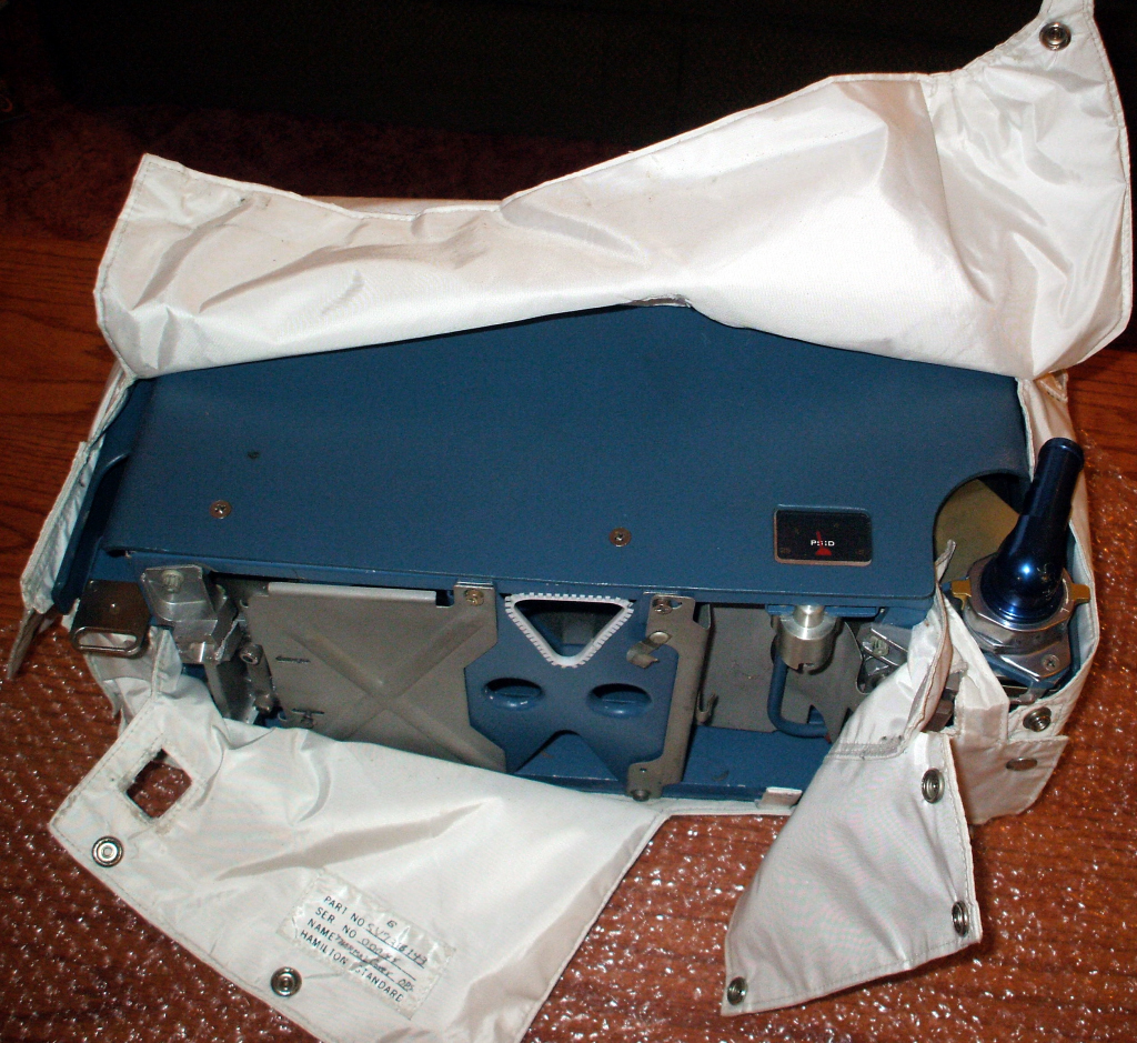
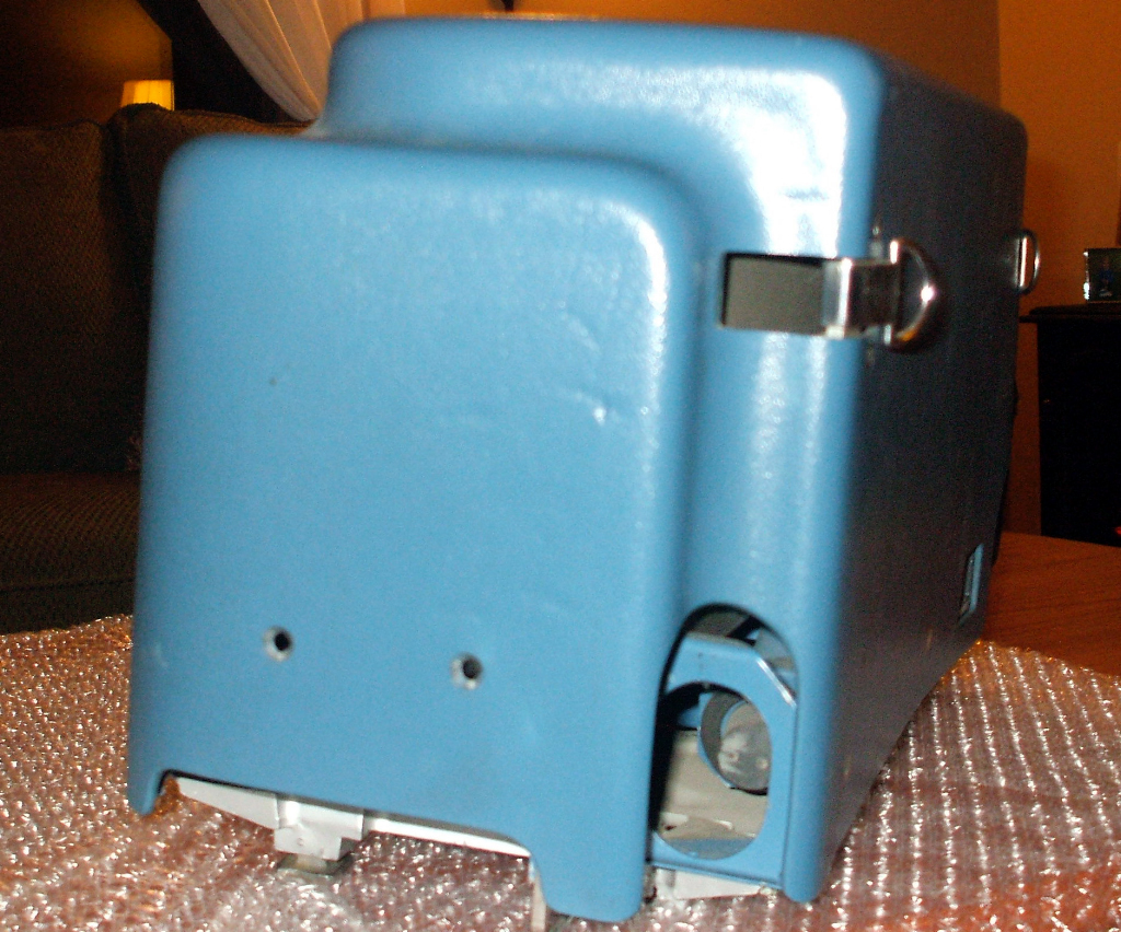
Bottom view with the white Beta cloth thermal covering, showing the 4 mounting feet (one of which is badly damaged) |
 |
Bottom view with the white Beta cloth thermal covering
open, showing the serial number for the thermal covering
and the working end of the Locking Pin (red arrow)
|
 |
Bottom view with the white Beta cloth thermal covering open, showing the Structural Plate at center. |
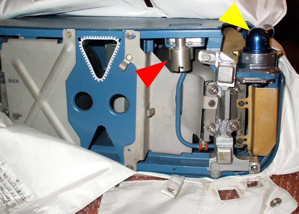 |
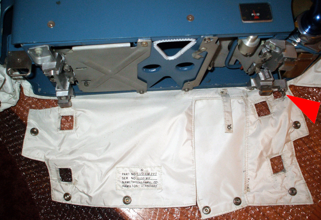
Bottom view with the white Beta cloth thermal covering open, showing the Structural Plate at the left. The Regulator Checkout Pressure Gage is marked with a red arrow, and the main OPS Oxygen Connector is marked with a yellow arrow. |
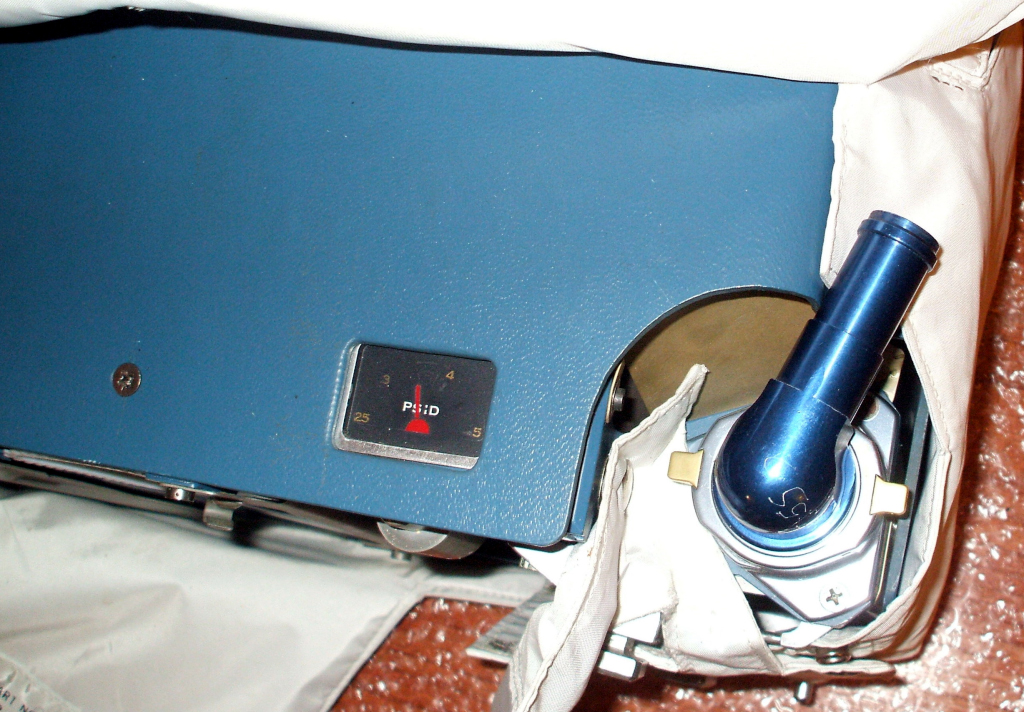 |
Front view showing the Regulator Checkout Pressure Gage (center) and blue OPS Oxygen Connector at right, which is attached to the Oxygen Connector Stowage Plate. |
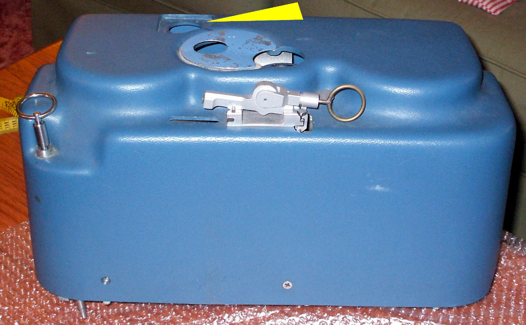 |
Rear view of the OPS with thermal covering removed. The blue shell is made of fiberglass. You can clearly see the Locking Pin, Pressure Gage, and Actuator. The yellow arrow shows the opening where the comm antenna was connected to the OPS. |
 |
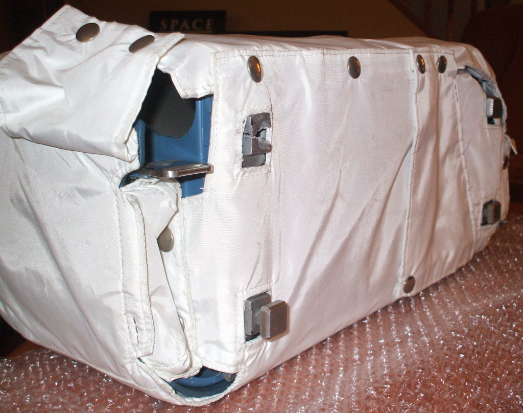
Side view showing oval opening where the main OPS Oxygen umbilical and Actuator cable emerged. The indentation in the shell formed a pathway for the umbilical and actuator cable to be wrapped around and over the top of the OPS when it was stowed. You can see this in the photo at the top of the page |
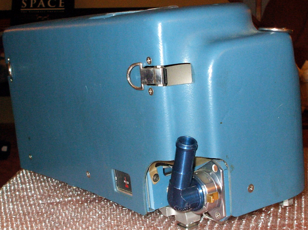 |
Opposite side from picture to the left, showing the clip
that was attached to be used with the OPS in case it
needed to be used in the helmet-mounted position. Also
note the Regulator
Checkout Pressure
Gage and the blue OPS Oxygen Connector at right,
which is attached to the Oxygen Connector Stowage Plate. |
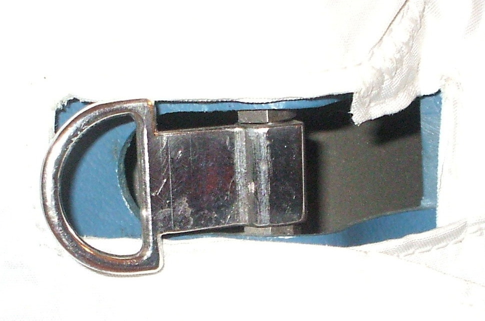 |
Helmet mounting clip |
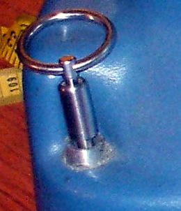 |
Locking Pin |
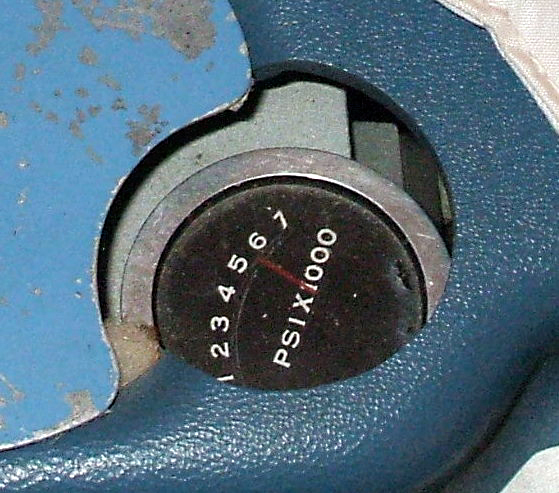 |
Pressure gage |
 |
Regulator Checkout Pressure Gage |
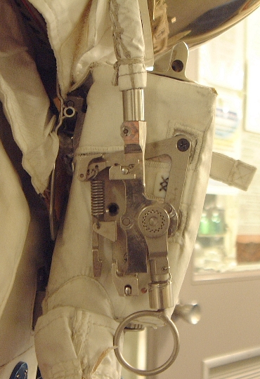
OPS Actuator & RCU
 |
 |
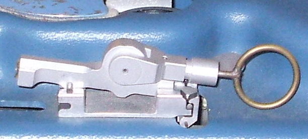 |
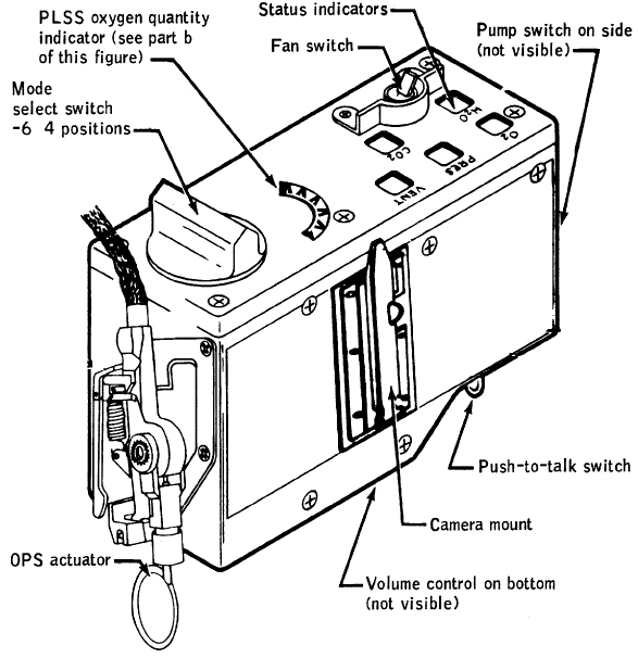
| RCU diagram showing OPS actuator mounted on the side |
Museum RCU with OPS actuator |
Detail from photo above showing
the Actuator assembly in its' stowed position on the top of the OPS |
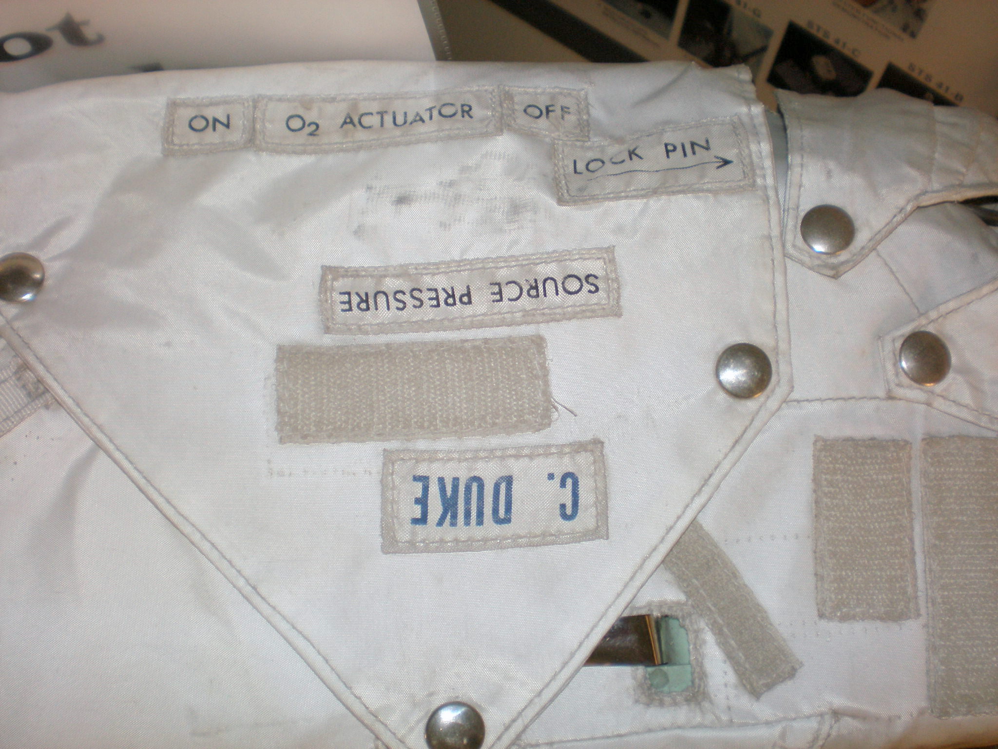
Antenna and Flaps: Charlie Duke's Training Unit
Photos courtesy K.C. Groneman and D.B. Eppler, NASA Johnson
 |
 |
 |
 |
 |
| Front view with antenna erect. Small flap open; hinged at the front. |
Front view with antenna erect and all flaps open. Antenna tip fits under fabric loop on the left. |
Antenna folded down and secured under loop. Left flap closed; hinged at front. |
Same configuration. Antenna tip visible at left. |
Right flap closed; hinged at the back. Small flap not closed; but probably should be. |
Journal Main Page