
LM Tapemeters, Associated Switches,
and Thrust-to-Weight Indicator
Copyright 2011 by Frank O'Brien and Eric M. Jones.
Last revised 23 May 2011.
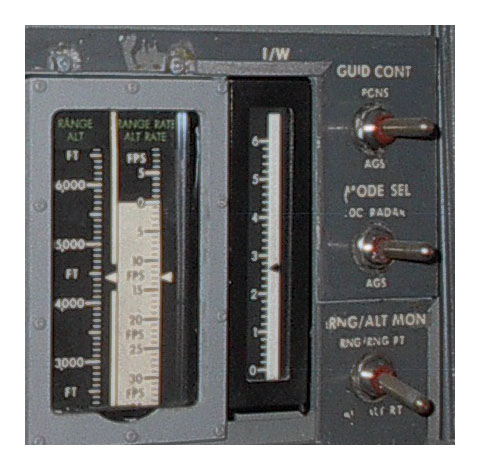
Photo detail showing a portion of Panel 1 in a LM simulator at the Cradle of Aviation Museum.
From left to right: Range/Altitude tapemeter; Range Rate/Altitude Rate Tape Meter; indicator
showing the LM's Thrust-to-Weight ratio; three selection switches. Photo by Frank O'Brien.
Tapemeters
Each of the two tapemeters had a fixed
pointer (the white triangle) to the right of the scale. The scale
was printed on a flexible "tape", which was moved up or down in
response to input from the Guidance system. Depending on the
setting of the bottom switch on the right, the tapemeters would
show Range (in feet) and Range Rate (in feet per second) or Altitude
and Altitude Rate. The bottom switch is labeled RNG/ALT
MON(itor) and the two positions are RNG/RNG RT (up) and ALT/ALT RT
(bottom).
The top switch is labeled GUID(ance) CONT(rol) which was used to select input from either the Primary Guidance and Navigation System (PGNS, up) or the Abort Guidance System (AGS, down).
The middle swtich, labeled MODE SEL(ect) had three positions depending on the data source: LDG (Landing) Radar (up), PGNS (center), and AGS(down).
The following is a description from Apollo Experience Report TN D-6722 "Lunar Module Display and Control Subsystems" by Andrew J. Farkas, released March 1972:
The relationship between LM acceleration in units of lunar gravity and "thrust-to-weight" can be demonstrated as follows. Let's define T = Thrust, M = LM mass, A = LM acceleration, g(l) = lunar gravitational acceleration, and W(l) = LM's lunar weight. Necessarily, the acceleration resulting from a force, T, applied to a mass, M, is
The following table provides Thrust-to-Weight(lunar) ratios at the beginning and end of the descent and similarly for the ascent. The data presented is dervied from pages 596 and 604-5 in Apollo: The Definitive Sourcebook by Richard Orloff and David Harland (Springer Praxis, 2006. Earth weights, W(e), have been converted to lunar weights W(l) via the identity W(l) = g(l) * W(e)/g(e), where g(e) is Earth's gravity. We have g(l) = 1.62 m/s2 and g(e) = 9.81 m/s2, so W(l) = 0.166 * W(e).
The LM weights at the beginning and end of the descent and the ascent are similar across the three early missions. Weights across the three later missions are higher than in the group of early missions but are similar with each other.
On the early missions, T/W would have been about 1.76 early in the descent and, as the descent fuel was consumed, gradually increased to about 3.63 at engine shutdown. On the later missions, T/W would have been about 1.63 at the start of the descent and about 3.28 at shutdown.
Although the T/W indicator was designed for use during the descent, with the descent stage left behind on the surface, values during the ascent on the early missions would have gone from 1.81 at ascent engine firing to 3.28 when the crew reach orbit. On the later missions, the values would have begun at about 1.78 and ended at about 3.25.
The top switch is labeled GUID(ance) CONT(rol) which was used to select input from either the Primary Guidance and Navigation System (PGNS, up) or the Abort Guidance System (AGS, down).
The middle swtich, labeled MODE SEL(ect) had three positions depending on the data source: LDG (Landing) Radar (up), PGNS (center), and AGS(down).
The following is a description from Apollo Experience Report TN D-6722 "Lunar Module Display and Control Subsystems" by Andrew J. Farkas, released March 1972:
The range indicator is a vertical-scale
indicator displaying range/altitude and range-rate/altitude-rate
by means of a moving scale indicating against a fixed pointer.
Two 10-foot tapes supply the moving scales that range up to 400
nautical miles for range/altitude and ±700 ft/sec for
range-rate/altitude-rate. The tape is part of a digital
servofeedback loop with a gray code word on the back corresponding to
numbers
observed on the front. An electrostatic sensor, or read head, determines the position of the tape by this coded word for comparison to the commanded position. If these two positions disagree, digital logic commands a direct current (dc) stepper motor to drive the tape to the correct position.
The indicator, in addition to the stepper motor and tape circuitry section, has two other operating sections: the processor and the interface (fig. 5). The processor contains the basic time-generating circuits for the indicator and performs the comparison of input against feedback to operate the motors. The interface section allows for the selection of the desired information source, stores needed input information, and provides digital conversion. Digital conversion is required because information enters the system as either a frequency word or as 15- to 18-bit digital words.
The indicator is packaged within a hermetically sealed enclosure. For the most part, the system electronics consist of micrologic (flat packs) integrated circuits that are mounted on 10 multilayer circuit boards. Each tape is made of 1-inch-wide, 3-rail-thick H film. One side of the tape has the range and range-rate display scales painted in black and white, while the other side has the gray code word with an exposed copper coating signifying a "1" and the lack of copper signifying a "0". A variable-polarity stepper motor is used to drive each tape. These 600-rpm motors operate through an 86:1 gear ratio for range tape drive and a 55:1 gear ratio for range-rate tape drive. The gear train is connected to a spring that is attached to separate rollers to maintain constant tension on the tape.
Thrust-to-Weight Indicator
The following is from TN D-6722:"The thrust-to-weight indicator was a
device used to measure and display
acceleration during lunar landing. the display consisted of a moving
pointer on a fixed vertical scale illuminated by an electroluminescent
lamp. The scale was calibrated from 0 to 6 lunar g. The display was
packaged within a hermetically sealed magnesium enclosure. The
enclosure consisted of a housing to which a cover and a plate glass
window were epoxy sealed. The internal mechanism was basically a simple
accelerometer consisting of a seismic mass, guide rods, a cord, a
pulley, a calibration spring, a damper assembly, and a pointer
assembly."
The relationship between LM acceleration in units of lunar gravity and "thrust-to-weight" can be demonstrated as follows. Let's define T = Thrust, M = LM mass, A = LM acceleration, g(l) = lunar gravitational acceleration, and W(l) = LM's lunar weight. Necessarily, the acceleration resulting from a force, T, applied to a mass, M, is
A
= T / M .
LM acceleration in units of lunar
gravity is A / g(l), which we can now write as
A
/ g(l) = T / [M
* g(l)] .
The weight of an objecting sitting on a
planetary surface is simply its mass multiplied by the local
gravitational acceleration or
W(l)
= M * g(l)
which allows us to write
A
/ g(l) = T / W(l)
which means that the measured LM
acceleration in units of lunar gravity is identical to the LM's
thrust-to-(lunar)weight ratio.
The following table provides Thrust-to-Weight(lunar) ratios at the beginning and end of the descent and similarly for the ascent. The data presented is dervied from pages 596 and 604-5 in Apollo: The Definitive Sourcebook by Richard Orloff and David Harland (Springer Praxis, 2006. Earth weights, W(e), have been converted to lunar weights W(l) via the identity W(l) = g(l) * W(e)/g(e), where g(e) is Earth's gravity. We have g(l) = 1.62 m/s2 and g(e) = 9.81 m/s2, so W(l) = 0.166 * W(e).
The LM weights at the beginning and end of the descent and the ascent are similar across the three early missions. Weights across the three later missions are higher than in the group of early missions but are similar with each other.
On the early missions, T/W would have been about 1.76 early in the descent and, as the descent fuel was consumed, gradually increased to about 3.63 at engine shutdown. On the later missions, T/W would have been about 1.63 at the start of the descent and about 3.28 at shutdown.
Although the T/W indicator was designed for use during the descent, with the descent stage left behind on the surface, values during the ascent on the early missions would have gone from 1.81 at ascent engine firing to 3.28 when the crew reach orbit. On the later missions, the values would have begun at about 1.78 and ended at about 3.25.
| Apollo 11, 12, 14 |
Apollo 15, 16, 17 |
|
| Pre-PDI LM weight (lun. lbs) |
5560, 5610, 5626 |
6050, 6047, 6058 |
| Descent Engine Max. Rated thrust
(lb) |
9870 |
9870 |
| Max. Trust / LM Lunar Weight |
1.78, 1.76, 1.75 |
1.63 |
| Landed LM Weight (lun. lbs) |
2667, 2735, 2704 |
3001, 3007, 3023 |
| Max. Thrust / Landed Weight |
3.70, 3.61, 3.65 |
3.29, 3.28, 3.26 |
| Ascent Stage Weight at Liftoff
(lun. lbs) |
1780, 1775, 1780 |
1802, 1808, 1816 |
| Ascent Engine Max. Rated Thrust
(lb) |
3218, 3224, 3218 |
3226, 3225, 3235 |
| Max. Thrust / Ascent Weight |
1.81, 1.82, 1.81 |
1.79, 1.78, 1.78 |
| Ascent Stage Weight at Orbit
Insertion for Docking |
979, 985, 977 |
988, 991. 998 |
| Max. Thrust / Ascent Weight |
3.29, 3.27, 3.29 |
3.27, 3.25, 3.24 |