[40] The consensus of the Commission and participating investigative agencies is that the loss of the Space Shuttle Challenger was caused by a failure in the joint between the two lower segments of the right Solid Rocket Motor. The specific failure was the destruction of the seals that are intended to prevent hot gases from leaking through the joint during the propellant burn of the rocket motor. The evidence assembled by the Commission indicates that no other element of the Space Shuttle system contributed to this failure.
In arriving at this conclusion, the Commission reviewed in detail all available data, reports and records; directed and supervised numerous tests, analyses, and experiments by NASA, civilian contractors and various government agencies; and then developed specific failure scenarios and the range of most probable causative factors. The sections that follow discuss the results of the investigation .
Analysis of the Accident
The results of the accident investigation and analysis will be presented in this and the following sections. Throughout the investigation three critical questions were central to the inquiry, namely:
Using mission data, subsequently completed tests and analyses, and recovered wreckage, the Commission identified all possible faults that could originate in the respective flight elements of the Space Shuttle which might have the potential to lead to loss of the Challenger. Potential contributors to the accident examined by the Commission were the launch pad (exonerated in Chapter IX of this report), the External Tank, the Space Shuttle Main Engines, the Orbiter and related equipment, payload/Orbiter interfaces, the payload, Solid Rocket Boosters and Solid Rocket Motors.
In a parallel effort, the question of sabotage was examined in detail and reviewed by the Commission in executive session. There is no evidence of sabotage, either at the launch pad or during other processes prior to or during launch.
[41] External Tank
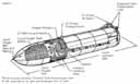
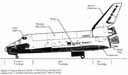
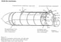
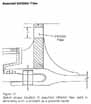
The External Tank contains propellants used by the Orbiter's three main engines during Shuttle launch and ascent to orbit. Structurally the tank is attached to and serves as the backbone of the Orbiter and the two Solid Rocket Boosters. Three primary structures-the liquid oxygen tank, the intertank and the liquid hydrogen tank-comprise the configuration. (Figure 1)
The External Tank delivers oxidizer and fuel from the propellant tanks to the Orbiter. The electrical subsystem includes instrumentation sensors, heaters, range safety electronics and explosives, and lightning protection and associated cabling. All flight instrumentation and electrical power are wired directly to the Orbiter. The thermal protection subsystem is the insulation applied to the tank's exterior. Its function is to prevent heat leakage into the propellants, to protect the External Tank from overheating during flight and to minimize ice formation while the Shuttle is on the pad.
Approximately 20 percent of the External Tank structure was recovered after the accident and the majority of the pieces were from the intertank and liquid hydrogen tank.1 The Commission initially considered all External Tank systems and subsystems in identifying possible faults or failures potentially contributing to the Challenger accident. Those potential contributors were:
The Commission examined the possibility that the STS 51-L accident could have been triggered by accidental detonation of the range safety system explosives. This potential fault was assessed using flight data, observed events, and recovered hardware. Most of the explosive charges for the External Tank emergency destruction system were recovered.2 Examination of this material established that none of it had exploded and thus could not have contributed to the accident (Photo C & D). Flight data verified that the External Tank range safety system was not activated .
The possibility of an imperfection existing in either the pressurized or nonpressurized External Tank structural elements that could grow to a sufficient size to cause structural failure was examined in detail. All construction history, structural qualification test data, proof test inspection records and x-rays were reviewed. One previously....
[42] ....undetected imperfection that was discovered during a reexamination of the x-rays was found in recovered hardware with no propagation indicated.3 Other data from the pre-launch ice and frost team inspections, film and video coverage, pressurization records and flight data revealed no evidence of leakage. The Commission concluded that no structural imperfections existed that could have grown to a size to create a leak or cause catastrophic failure of the External Tank.
Possible damage to the liquid hydrogen tank at lift off was considered. The ice and frost team observed no vapor or frost that would indicate a leak. The liquid hydrogen vent arm retracted as expected during launch and did not recontact the tank or solid booster.4 Photo analysis and television monitoring did not indicate that any debris contacted the tank. Therefore, damage to the liquid hydrogen tank at lift off was determined to be highly improbable.
The possibility that abnormally high structural loads caused an External Tank failure was examined. Analysis indicated that there were no excessive loading conditions based on lift off and flight data prior to the explosion. The maximum structural load produced was less than 80 percent of the allowable design load.5 The structural implications of vent and flow control valve operation was examined and found not to be a factor.
The possibility of a structural failure due to overheating was assessed with several causes postulated: high heating due to abnormal trajectory, loss of the thermal protection system, a hot gas leak from the Solid Rocket Motor and a liquid hydrogen leak from the External Tank. The trajectory was normal until well after the Solid Rocket Motor leak was observed at 58 seconds. Maximum aerodynamic heating would not have occurred until approximately 90 seconds.6 At 73 seconds, heating was well within tank component structural capability. Based on careful review of pre-launch and flight films and data, the Commission found no evidence that any thermal protection foam was lost during the launch and ascent.
The possibility of a leak from the hydrogen tank resulting in overheating was addressed. Tests indicated that small leaks (0.037 lbs/second) would have been visible. In addition, if there was a liquid hydrogen leak at lift off, it would have been ignited by either the Solid Rocket Booster ignition or Space Shuttle Main Engine ignition.7
The resultant flame would have ignited the Solid Rocket Booster attach ring foam insulation almost immediately. Copious quantities of dense black smoke and open flames would be evident in such a case and would have continued for as long as the leak burned. Smoke and flames in these quantities were not observed at lift off nor anytime throughout the flight. It is therefore concluded that an initial liquid hydrogen tank leak was improbable, and that the only possible cause for overheating the tank was the impingement of leaking Solid Rocket Motor gases. This resulted in the ultimate breakup of the External Tank.
The recovered external foam insulation on the External Tank was scorched and discolored in various locations.8 Burn patterns across the pieces of insulation on the External Tank indicate that various areas were subjected to fire both before and after the External Tank broke up in flight.
The Commission reviewed the External Tank's construction records, acceptance testing, pre-launch and flight data, and recovered hardware and found nothing relating to the External Tank that caused or contributed to the cause of the accident.
Space Shuttle Main Engines
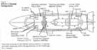
A cluster of three Space Shuttle Main Engines operates simultaneously with the Solid Rocket Boosters during the initial ascent phase of flight and provides primary propulsion until the Shuttle has attained orbital velocity. These engines use liquid hydrogen as the fuel and liquid oxygen as the oxidizer. Both the liquid hydrogen and oxygen are stored in the External Tank and are transferred to the engines under pressure. During the mission the engines operate for about 8.5 minutes.
Engine thrust is controlled by throttling and has ranged from 65 to 104 percent of a specified thrust level. At sea level, 100 percent equals 375,000 pounds of thrust per engine.
Pitch, yaw and roll control of the Orbiter is provided by gimbals on each engine. Gimbaling is operated by two hydraulic servo-actuators, one for pitch motion and the other for yaw motion, with roll controlled by a combination of both pitch and yaw. These servo-actuators are commanded by the Orbiter's computer.
An electronic controller is attached to the forward end of each engine. Each controller is a self....
....contained system that monitors engine checkout, control and status, and sends the data to the Orbiter. Each of the three engine interface units in turn sends its data to the Orbiter computers and relays commands from the computers to the engines.
A propellant management subsystem of manifolds, distribution lines and valves controls the flow of liquids from the External Tank to the engines, and the flow of gaseous hydrogen and oxygen from the engines into the External Tank to maintain pressurization.
All three main engines from the Challenger, No. 2020 in position 2, No. 2021 in position 3, and No. 2023 in position 1, were recovered in large part on February 23, 1986, off the Florida coast in about 85 feet of water. All parts were recovered close to one another, and the engines were still attached to the thrust structure.9 All engine gimbal bearings had failed, apparently because of overload on water impact.
All metallic surfaces were damaged by marine life, except titanium surfaces or those parts that were buried under the ocean bottom. The metal fractures, examined at 3x magnification, showed rough texture and shear lips, which appeared to be caused by overloads due to water impact.10 No pre-accident material defects were noted.
The engine nozzles were sheared at the manifolds. The main combustion chambers, main injectors and preburners of each engine were attached to one another. The six hydraulic servo-actuators used to control engine gimbaling were attached to segments of the Orbiter thrust structure.11
Sections of the main propulsion system fuel and liquid oxygen feedlines and feedline manifolds were recovered, as well as the External Tank/Orbiter disconnect assembly in the mated configuration. A portion of the oxidizer inlet duct was attached to the interface of engine 2020. All preburner valves were recovered.12
The main engine controllers for both engines 2020 and 2021 were recovered. One controller was broken open on one side, and both were severely corroded and damaged by marine life. Both units were disassembled and the memory units flushed with deionized water. After they were dried and vacuum baked, data from these units were retrieved.13
All engines had burn damage caused by internal overtemperature typical of oxygen-rich shutdown. Thus, the loss of hydrogen fuel appears to have initiated the shutdown. The Commission reviewed engine and ground measurements made while the three engines were prepared for launch. Ambient temperature during pre-launch was the coldest to date, but preflight engine data were normal.14 These data were also compared with Challenger engine data during the flight 61-A pre-flight period. All differences seen between the two missions were due either to planned variations in the pre-launch sequence or the cold ambient conditions during the preflight period for flight 51-L. These differences did not affect engine [44] performance during the powered flight phase of the mission.
Preflight data gave no evidence of any propellant leaks (fuel or oxidizer) in the aft compartment. For the powered flight phase all the parameters of the engine aft compartment that could give an indication of a leak were selected from the overall flight 51-L measurement list. The majority of those parameters were either ground measurements or those recorded during the flight but not telemetered to the ground.15 Among parameters that were telemetered during the flight were skin temperature measurements that gave no indication of a hot gas or other leak in the engine compartment.
Analysis of the engine start data showed all three engine starts were normal and no anomalies were found.
An assessment of the engine performance in the final seconds of the mission before the accident was compared with similar periods on all flights of the Challenger engines. The assessment showed the engine performance on flight 51-L was consistent with previous flights.16
The first abnormal engine indication was a drop in engine fuel tank pressure at 72.564 seconds. As fuel pressure dropped, the control system automatically responded by opening the fuel flowrate valve. The turbine temperatures then increased because of the leaner fuel mixture.
[45] The increased temperature caused an increase in pump speed. This could not, however, increase the fuel pressure because of a decrease in fuel tank top (ullage) pressure resulting from the burned through hydrogen tank leakage. When the fuel pump pressures dropped below 140 pounds per square inch, the programed control system disqualified the measured data because it was past reasonable limits. This caused the fuel flowrate and high-pressure fuel pump discharge pressure to decrease, while the lack of load allowed the pump's speed to increase. The decreased fuel flow caused a drop in fuel preburner chamber pressure, though the fuel preburner oxygen valve was then advancing toward a more open position. The mixture ratio in the fuel preburner became leaner, which raised high-pressure fuel turbine discharge temperatures above the redline limits. This caused the engine control system to start automatic shutdown of the engine.
The engine flight history showed that engine 2023 flew four previous times while engines 2020 and 2021 had flown five previous missions.17 The flight data from flight 51-L compared well with flight data from all previous flights.
The analysis of flight data confirmed that the Space Shuttle Main Engines operated properly while reacting to changing external conditions. Previous engine tests suggest that the highpressure pumps are the most likely components to fail, because of either bearing or turbine blade failure. There was no evidence of either in flight 51-L. Engine operation was normal until the fuel inlet pressure dropped. As the pressure decreased, the engine responded in a predictable manner. Automatic shutdown of engine 2023 was verified by telemetry data. Data recovered from the salvaged engine 2021 control computer verify that this engine also had begun shutdown. Salvaged control computer data from engine 2020 showed that this engine was within 20 milliseconds of shutdown when the computer stopped.18 Inspection of recovered engine hardware verified that all engines were shut down in a fuel-lean or oxygen-rich condition which resulted in burn through and erosion of the engine hot gas circuits.
The Commission concluded that the Space Shuttle Main Engines did not cause or contribute to the cause of the Challenger accident.
Orbiter and Related Equipment
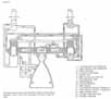
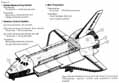
The Orbiter subsystems include propulsion and power, avionics, structures, thermal and environmental control and life support, mechanical and interface, and other government furnished essential equipment. Onboard government furnished equipment for STS 51 -L included the remote manipulator arm system, extravehicular mobility units, extravehicular activity hardware, television, equipment worn by the crew, storage provisions and communication equipment.
The significant pieces of Orbiter structure recovered included all three Space Shuttle Main Engines, the forward fuselage including the crew module, the right inboard and outboard elevons, a large portion of the right wing, a lower portion of the vertical stabilizer, three rudder speed brake panels and portions of mid-fuselage side walls from both the left and right sides.19 This represents about 30 percent of the Orbiter but does not provide sufficient evidence to establish conclusively the complete failure sequence of the entire Orbiter spacecraft. However, there was sufficient evidence to establish some of the structural failure modes that resulted in the Orbiter's destruction.
All fractures and material failures examined on the Orbiter, with the exception of the main engines, were the result of overload forces, and they exhibited no evidence of internal burn damage or exposure to explosive forces. This indicated that the destruction of the Orbiter occurred predominantly from aerodynamic and inertial forces that exceeded design limits. There was evidence that during the breakup sequence, the right Solid Rocket Booster struck the outboard end of the Orbiter's right wing and right outboard elevon. Additionally, chemical analysis indicated that the right side of the Orbiter was sprayed by hot propellant gases exhausting from the hole in the inboard circumference of the right Solid Rocket Booster. Evaluation of the Orbiter main engines showed extensive internal thermal damage to the engines as a consequence of oxygen-rich shutdown that resulted from a depletion of the hydrogen fuel supply. The supply of hydrogen fuel to the main engines would have been abruptly discontinued when the liquid hydrogen tank in the External Tank disintegrated.
The crew module wreckage was found submerged in about 90 feet of ocean water concentrated in an area of about 20 feet by 80 feet. Portions of the forward fuselage outer shell structure were found among the pieces of crew module recovered.20 There was no evidence of an internal explosion, heat or fire damage on the forward....
....fuselage/crew module pieces. The crew module was disintegrated, with the heaviest fragmentation and crash damage on the left side. The fractures examined were typical of overload breaks and appeared to be the result of high forces generated by impact with the surface of the water. The sections of lower forward fuselage outer shell found floating on the ocean surface were recovered shortly after the accident. They also contained crush damage indicative of an impact on the left side. The consistency of damage to the left side of the outer fuselage shell and crew module indicates that these structures remained attached to each other until impact with the water.
The Orbiter investigation consisted of a review of all Orbiter data and vehicle parts retrieved. Also reviewed were vehicle and equipment processing records and pre-mission analyses.
All orbital maneuvering system measurements such as temperatures, pressures, events, commands, stimuli, and switch positions were reviewed with all related computer data. There were no indications of abnormal behavior. All temperature and pressure transducers active during ascent for the reaction control system were reviewed, including thruster chamber pressure, leak temperature, line temperature, propellant tank, helium tank and propellant line transducers. Nothing was found that could have contributed to the accident.
Auxiliary power unit pressures and temperatures were reviewed, and no abnormal conditions were observed during ascent. Selected hydraulic measurements, including system pressures, fluid quantities and most temperatures in the aft compartment and in the wing cavity containing the elevon actuator supply lines, were reviewed by the Commission, and no abnormality was found. All fuel cells and power reactant storage and distribution subsystem measurements were reviewed and found to be normal during all phases of ground and flight operation prior to the accident. All available pyrotechnic firing control circuit measurements were reviewed, along with radiography, shear bolt review and debris reports, ....
....and there were no unintentional firing command indications.21 All available data regarding range safety and recovery system batteries were reviewed, and no indications were found that the batteries were involved in initiating the accident.
Guidance, navigation and control subsystems data were reviewed, and it appears that the subsystems performed properly. All subsystem sensors and software apparently performed as designed until data loss. Inertial measurement unit data from the preflight calibration through signal loss were found to be normal. All data processing system related data were reviewed, and nothing significant was found. Data review of the electrical power distribution and control subsystem indicated that its performance was normal until the time of the accident.22 All communication and tracking system parameters active during launch were evaluated and found to be normal. No instrumentation abnormalities were observed during the pre-launch and launch period before signal loss.
Structures evaluation included analysis of ground and flight data (loads, temperatures, pressures and purge flows), hardware changes and discrepancy reports since the last Challenger flight, and wreckage. The Commission found that no Orbiter structural elements contributed to the accident.
Orbiter structural pre-launch temperature measurements were evaluated and found to be within specified limits.
Data related to the atmospheric revitalization system, which maintains cabin atmosphere, were evaluated.23 During pre-launch, launch and until signal loss, data indicated that both of the water coolant loops were normal, the pressure control system functioned normally, all fans functioned normally, and all switches and valve positions were proper.
Active thermal control subsystem data indicated that both of the freon coolant loops functioned normally, the ammonia boiler system was normal, and all switch and valve positions were proper. 24
The water management subsystem functioned [48] normally during the flight. The smoke detection and fire suppression subsystem and airlock support subsystem both functioned normally. The waste collection subsystem is inoperative during the launch phase, and no data were available.25
No mechanical system abnormalities were identified. The vent doors remained open throughout the launch. The payload bay doors remained latched. All landing gear were up and locked, all doors remained closed and locked, and the remote manipulator system and payload retention system remained latched. Film and Orbiter interface data showed that there was no premature Orbiter/External Tank separation.
Video tapes and photographs indicated the crew egress hatch, which caused the launch delay on the preceding day, operated properly.
The onboard government furnished equipment configuration and pre-launch processing were reviewed and determined to have been flightready with no unusual or abnormal conditions.
Based on this review and assessment, the Commission concluded that neither the Orbiter nor related equipment caused or contributed to the cause of the accident.
Payload/Orbiter Interfaces
Interfaces between the Orbiter and the payload serve to attach the cargo to the Orbiter or provide services from the Orbiter to cargo items. These interfaces are mechanical, thermal, avionics, power and fluid systems.
The Spartan-Halley payload was located in the front of the payload bay, attached to the equipment support structure carrier. The Tracking and Data Relay Satellite (TDRS) was attached to the Inertial Upper Stage (IUS) booster rocket used to move the TDRS into geosynchronous orbit. In the aft flight deck, payload interfaces consisted of a standard switch panel, a payload deployment and retention system, and display and control panels for use with the payload. Payloads in the middeck area were in the stowage lockers. These were radiation monitoring, phase partitioning, fluid dynamics experiments, three student experiments, the Teacher in Space Project and the Comet Halley monitoring program.
Thermal interfaces between the Orbiter and the payload in the aft flight deck and middeck consisted of the Orbiter's purge, vent and fluid heat exchanger systems. Thermal interface for TDRS/IUS, Spartan-Halley, and the experiments and projects were provided by the Orbiter environment control and life support system.
Electrical power and avionics were provided to the payload through standard interface panels along both side of the cargo bay. In the aft flight deck, the control and display panels supplied by the Orbiter provided the avionics and power interfaces for TDRS/IUS. The experiments and projects constituting the middeck payload had no interfaces with avionics and power systems.
The only direct payload loads data from STS 51-L were accelerometer data recorded through the Orbiter umbilical prior to lift off. Accelerometer data from the payload bay and the crew cabin compared favorably with previous flights. Results indicate that payload loads on STS 51-L were similar to those of STS-6 and were within design levels and pre-launch predictions.
The Commission found that all payload elements had been certified safe for flight, and records for integration of hardware met engineering requirements. Temperatures during prelaunch and ascent were normal. Reconstructed lift off loads were below those used in the flight readiness certification. The relay satellite's rate gyro data correlated with those for the Orbiter and boosters during ascent. Fittings attaching the payloads to the Orbiter remained in operation, as shown by telemetered data from monitoring microswitches.
The Commission found no discrepancies in the Orbiter/payload interface performance that might have contributed to the Challenger accident.
Payloads, Inertial Upper Stage, and Support Equipment
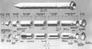
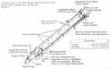
The payload bay of the Orbiter Challenger contained a Tracking and Data Relay Satellite (TDRS) attached to an Inertial Upper Stage (IUS) booster rocket, and associated airborne support equipment. The IUS contained two solid rocket motors (SRMs): SRM-1 and SRM-2. The combined weight of these components was about 40,000 pounds. About five percent of the payload, IUS, and support equipment package was recovered from the ocean. Components recovered included segments of the cases of both IUS SRMs, the ignition safe/arm device for each SRM, the igniter for SRM-2, fragments of unburned propellant from each SRM, five explosive....
.....separation bolts that secure the two SRMs together, the forward support equipment trunnions, the aft trunnions with spreader beams, and an undetonated section of explosive fasteners.
There was no evidence of scorching, burning, or melting on any of the components and structure recovered, and all fractures were typical overload fractures. The safe arm device for each IUS SRM was in the safe position, the five explosive SRM-1/SRM-2 separation bolts were intact, and pieces of propellant were not burned, indicating that the SRMs had not ignited. The two aft trunnion spreader beams were intact but were bent in the downward direction relative to the Orbiter. The right spreader beam was cracked and deformed about 7.5 inches, and the left spreader beam was cracked and deformed about 1.5 inches.26 These deformations indicate that the payload and upper stage package was intact and secure in the cargo bay while being subjected to significant inertial flight loads.
The inertial upper stage is a two-stage, solidrocket-propelled, three-axis controlled, inertially navigated upper stage rocket used to deliver spacecraft weighing up to approximately 5,000 pounds from the Shuttle parking orbit to geosynchronous orbit. It includes the stage structure; solid rocket motors; a reaction control subsystem; avionics for telemetry, tracking and command; guidance, navigation and control; data management; thrust vector control; electrical power sources and electrical cabling; and airborne software.
Assessment of possible upper stage contribution to the accident centered on the elimination of three possible scenarios: Premature upper stage rocket ignition, explosion/fire in the payload bay, and payload shift in the payload bay.
Premature ignition of either the upper stage stage 1 and/or stage 2 motor while still in the Orbiter bay would have resulted in catastrophic failure of the Orbiter. Potential causes for premature ignition were electrostatic discharge, inadvertent ignition command and auto-ignition. Each would have caused a rapid increase in the Orbiter payload bay temperature and pressure, and would have been immediately followed by structural damage to the payload bay doors. The payload bay temperatures remained essentially constant, and the Orbiter photographic and telemetry data indicated the payload doors remained closed and latched from lift off until signal loss.27 Both indications verified that there was no ignition of the IUS solid rocket motors.
An IUS component explosion or fire could have damaged critical systems in the Orbiter by overheating or impact. Five sources other than an upper stage motor pre-ignition were identified as potential origins of a fire or explosion in the payload bay: (1) release and ignition of IUS hydrazine from the reaction control system tanks, (2) fire or explosion from an IUS battery, (3) [50] impact or rupture of a motor case and subsequent ignition of exposed propellant, (4) fire of electrical origin due to a short, and (5) fire or inadvertent ignition of pyrotechnic devices due to radio frequency radiation. Thermal measurements in the propellant tank and in components adjacent to the propellant tanks indicated no abnormalities. Pre-launch and thermal measurements in the Orbiter payload bay and in TDRS near the reaction control system were stable throughout the ascent period. A fire and/or explosion resulting in shrapnel from an IUS battery was eliminated based on pre-launch monitoring of open circuit voltages on all batteries, except the support equipment batteries. Location of these batteries made the potential for damage to critical systems very small if they burned or exploded. Motor case impact or rupture and resulting exposure and propellant ignition was determined improbable because batteries and reaction control system burning or explosion were eliminated by flight data analysis. They were the only potential sources for IUS heating and high velocity shrapnel. Propellant burning was not indicated by payload bay thermal measurements. Electrical shorting was eliminated as a fire source in the payload bay because IUS electrical and Orbiter voltage monitors were normal at launch and during STS 51-L ascent. Fires initiated by radio frequency radiation due to inadvertent IUS, TDRS, or ground emittance were eliminated because data showed worst case radio frequency radiation during ascent was less than ground-emitted radiation to the payload bay during pre-launch checkout. The ground-emitted radiation was within specified limits.
IUS/TDRS payload shifting or breaking free within the Orbiter due to structural failure or premature separation was investigated. Such a shift could have resulted in severe Orbiter damage from a direct impact, or could have induced a significant shift in the Challenger vehicle center of gravity and possibly affected flight control.28 Four possible faults that could have led to Orbiter damage or substantial payload shift were considered: IUS stage 2/TDRS separation, IUS stage 1/stage 2 separation, IUS/TDRS separation from the airborne support equipment and IUS/airborne support equipment separation from Orbiter. All were eliminated because dynamic response data conclusively showed that IUS/TDRS responded normally until the final loss of data. Further, TDRS data, which pass through the IUS stage 1/stage 2 and support equipment, were continuous until data loss, verifying that these elements did not separate.
The TDRS spacecraft weighs approximately 4,905 pounds and is 9.5 feet in diameter and 19.5 feet long. The forward 11 feet contain six deployable appendages, two solar arrays, one space-ground link antenna, and two single access antennas. The spacecraft body structure consists of a payload structure and a spacecraft structure. These structures house the tracking and telemetry and command subsystem, power subsystem, thermal control subsystem, ordnance subsystem, reaction control subsystem and attitude control subsystem.
Telemetry data were transmitted from TDRS from approximately 48 hours prior to launch through signal loss. The telemetry system was functioning properly, and the data indicated that the telemetry processor was in its normal operational mode and all power supply voltages and calibration voltages were normal. There were no changes through the countdown to the time of structural breakup, when all telemetry abruptly halted. The telemetry tracking and control subsystems command and tracking elements were inactive during the countdown through ascent, and no changes were noted, indicating that the TDRS was not commanded to alter its launch configuration.
The TDRS power subsystem had a total of 138 telemetry indications. These were the main data source used to determine the power subsystem activity. Analyzing this telemetry showed all subsystem elements performed normally.
The TDRS thermal control subsystem was designed to maintain proper temperatures primarily by passive means. Also, there is a thermostatically controlled heater system to ensure minimum required temperatures are maintained. The thermal subsystem was monitored by 82 configuration status indicators and 137 analog temperature channels. This telemetry showed that the TDRS remained in its normal thermal configuration and experienced normal temperatures until signal loss.
No data indicated that the IUS separated from TDRS, that any deployable appendage ordnance had been fired or that any appendage motion had begun.
The TDRS reaction control system was inactive at launch and required an IUS command and two ground commands to activate any propellant.
[51] Telemetry indicated no valve actuation, changes in tank pressures or temperatures, or propellant line temperature violations. Further, there was no telemetry that would suggest a hydrazine leakage or abnormality and no indications that the TDRS reaction control system contributed to the accident.
During the launch phase, the attitude control subsystem was disabled except for the gyros and associated electronics necessary to provide the telemetry. All telemetry parameters reflecting attitude control subsystem configuration remained normal and unchanged during the STS 51-L pre-launch and post-launch periods.
The TDRS was mounted in a cantilevered fashion to the IUS by an adapter ring that provided structural, communications and power interfaces. Structural integrity loss indications would have been observed by interruptions in telemetry or electrical power. TDRS telemetry during the launch phase was transmitted by electrical cable to the IUS and interleaved with upper stage data. If separation had occurred at either the TDRS/IUS interface or the IUS/support equipment interface, TDRS data would have stopped. There was no abnormal telemetry until signal loss of all vehicle telemetry. TDRS also received power from the Shuttle via the IUS through the same interfaces. There were no indications of TDRS batteries coming on line. This indicates that structural integrity at the TDRS and IUS interfaces was maintained until the structural breakup. Additionally, an inspection of the recovered debris gives the following indications that the TDRS/IUS remained intact until the structural breakup. First, the separation bank lanyards frayed at the end where they attached to the band, indicating that the spacecraft was pulled forcefully from the adapter. Second, the V-groove ring structure at the top of the adapter was torn from its riveted connection to the adapter, indicating that a strong shear existed between the spacecraft and IUS which would only be generated if the two were still attached. Finally, the adapter base was torn where it attached to the IUS, again indicating high tension and shear forces. There were no indications from telemetry or recovered debris that showed that the structural integrity of the satellite or the satellite/stage interface had been compromised.
The TDRS records at Kennedy were reviewed for technical correctness and to verify that no open safety related issues existed. There were no findings that revealed unsafe conditions or that any safety requirements had been violated or compromised.
A review and assessment of Spartan Halley performance was conducted to establish any possible contributions to the STS 51-L accident. The Spartan Halley was unpowered except for the release/engage mechanism latch monitor. Its electrical current was in the order of milliamps and the telemetry records obtained from the Orbiter indicated that the latches were in the proper configuration and thus Spartan Halley remained firmly attached during flight. In addition, the TDRS spacecraft data indicated there was no interaction from Spartan. Therefore, the Spartan Halley and its support structure remained intact. The payload bay temperature in the vicinity of Spartan was 55 degrees Fahrenheit indicating no abnormal thermal conditions.
As a result of detailed analyses of the STS 51-L Orbiter, the payload flight data, payload recovered hardware, flight film, available payload pre-launch data and applicable hardware processing documentation, the Commission concluded that the payload did not cause or contribute to the cause of the accident.
Solid Rocket Booster
The Solid Rocket Booster comprises seven subsystems: structures, thrust vector control, range safety, separation, electrical and instrumentation, recovery, and the Solid Rocket Motor.
All recovered Solid Rocket Booster pieces were visually examined, and selected areas were extracted for chemical and metallurgical analysis.
The exterior surfaces of the Solid Rocket Boosters are normally protected from corrosion by an epoxy resin compound. There were several small areas where this protective coating was gouged or missing on the pieces recovered and, as a result, the exposed metallic surfaces in the areas were corroded. The damage to the protective coating was most likely the result of detonation of the linear shaped charges and water impact. There was no obvious evidence of major external flame impingement or molten metal found on any of the pieces recovered. All fracture surfaces exhibited either the characteristic markings of rapid tensile overload, a complete bending failure due to overload, or a separation fracture due to the detonation of the linear shaped charges.
[52] Other pieces of the right Solid Rocket Motor aft field joint showed extensive burn damage, centered at the 307 degree position.
Most of the Solid Rocket Motor case material recovered contained pieces of residual unburned propellant still attached to the inner lining of the case structure.29 The severed propellant edges were sharp, with no unusual burn patterns. Propellant recovered with a forward segment of the booster exhibited the star pattern associated with the receding shape of the propellant at the front end of the Solid Rocket Motor. There was no evidence found of propellant grain cracking or debonding on the pieces recovered. Casting flow lines could be distinguished on the propellant surfaces in several areas. This is a normal occurrence due to minor differences in the propellant cast during the installation of the propellant in the motor case structure.
Hardness tests of each piece of the steel casing material were taken before the propellant was burned from the piece. All of the tests showed normal hardness values.
One of the pieces of casing showed evidence of O-ring seal tracks on the tang of the field joint. The tracks were cleaned with hexane to remove the grease preservative that had been applied after recovery of the piece, and samples of the track material were removed for analysis. Chemical analysis of the track material showed that the tracks were not composed of degraded O-ring seal material.
The possible Solid Rocket Booster faults or failures assessed were: structural overload, Solid Rocket Motor pressure integrity violation, and premature linear shaped charge detonation.
Reconstructed lift off and flight loads were compared with design loads to determine if a structural failure may have caused the accident. The STS 51-L loads were within the bounds of design and capability and were not a factor. Photographic and video imagery confirmed that both Solid Rocket Boosters remained structurally intact until the time of the explosion except for the leak observed on right Solid Rocket Motor.
The possibility that the range safety system prematurely operated, detonating the linear shaped charges was investigated. The linear....
|
Aft ET/SRB Struts |
|
|
| |||||
|
. | ||||||||
|
|
|
|
|
|
|
| |
|
. | ||||||||
|
P8 |
|
|
|
|
|
|
|
|
|
P9 |
|
|
|
|
|
|
|
|
|
P10 |
|
|
|
|
|
|
|
|
|
P11 |
|
|
|
|
|
|
|
|
|
P12* |
|
|
|
|
|
|
|
|
|
P13 |
|
|
|
|
|
|
|
|
.....shaped charges were photographically observed to destroy both Solid Rocket Boosters at 110 seconds after launch when commanded to do so by the Range Safety Officer and therefore could not have discharged at 73 seconds after launch causing the accident. The possibilities of the Solid Rocket Boosters separating prematurely from the External Tank, the nozzle exit cone prematurely separating or early deployment of the recovery system were examined. Premature activation of the separation system was eliminated as a cause of failure based on telemetry that showed no separation commands. There were no indications that the nozzle exit cone separated. The recovery system was observed photographically to activate only after the Solid Rocket Boosters had exited the explosion.
In addition to the possible faults or failures, STS 51-L Solid Rocket Booster hardware manufacturing records were examined in detail to identify and evaluate any deviations from the design, any handling abnormalities or incidents, any material usage issues, and/or other indication of problems that might have importance in the investigation. Based on these observations, the Commission concluded that the left Solid Rocket Booster, and all components of the right Solid Rocket Booster, except the right Solid Rocket Motor, did not contribute to or cause the accident.
The Right Solid Rocket Motor
As the investigation progressed, elements assessed as being improbable contributors to the accident were eliminated from further consideration. This process of elimination brought focus to the right Solid Rocket Motor. As a result, four areas related to the functioning of that motor received detailed analysis to determine their part in the accident:
Where appropriate, the investigation considered the potential for interaction between the areas.
Structural Loads Evaluation
Structural loads for all STS 51-L launch and flight phases were reconstructed using testverified models to determine if any loading condition exceeded design limits.
Seconds prior to lift off, the Space Shuttle Main Engines start while the Solid Rocket Boosters are still bolted to the launch pad. The resultant thrust loads on the Solid Rocket Boosters prior to lift off were derived in two ways: (1) through strain gauges on the hold-down posts, and (2) from photographic coverage of Solid Rocket Booster and External Tank tip deflections. These showed that the hold-down post strain data were within design limits. The Solid Rocket Booster tip deflection ("twang") was about four inches less than seen on a previous flight, STS-6, which carried the same general payload weight and distribution as STS 51-L. The period of oscillation was normal. These data indicate that the Space Shuttle Main....
...Engine thrust buildup, the resulting forces and moments, vehicle and pad stiffness, and clearances were as expected. The resultant total bending moment experienced by STS 51-L was 291 x 106 inch-pounds, which is within the design allowable limit of 347 x 106 inch-pounds.
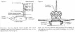
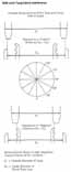
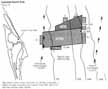
The STS 51-L lift off loads were compared to design loads and flight measured loads for STS-1 through STS-7 (Figure 9). The Shuttle strut identification is shown in Figure 10. The loads measured on the struts are good indicators of stress since all loads between Shuttle elements are carried through the struts. The STS 51-L lift off loads were within the design limit.
Because the Solid Rocket Motor field joints were the major concern, the reconstructed joint loads were compared to design loads. Most of the joint load is due to the booster's internal pressure, but external loads and the effects of inertia (dynamics) also contribute. The Solid Rocket Motor field joint axial tension loads at lift off were within the design load limit (17.2 x 10⁶ pounds). The highest load occurred at the forward field joint, 15.2 x 10⁶ pounds. The midjoint load was 13.9 x 10⁶ pounds, while the aft joint showed 13.8 x 10⁶ pounds load.
Loads were constructed for all in-flight events, including the roll maneuver and the region of maximum dynamic pressure. A representative measure of these loads is the product of dynamic pressure (q) and the angle of attack (a) [Greek letter alpha]. Since the Shuttle is designed to climb out at a negative angle of attack, the product is a negative number. The loads in the q x a pitch plane are shown in Figure 11. Although the q x a variations in loads due to wind shear were larger than expected, they were well within the design limit loads.
The Solid Rocket Motor field joint axial tension loads were substantially lower at maximum dynamic pressure than at lift off: 11.6 x 10⁶ pounds for the forward field joint and 10.6 x 10⁶ pounds for the aft field joint. Compared to the internal pressure loads, the dynamic variations due to wind shear were small-about 1/15 those of the pressure loads. These loads were well below the design limit loads and were not considered the cause of the accident.

Case Membrane Failure
The case membrane is the half-inch thick steel wall of the rocket between the joints. The possibility that the failure was initiated by anomalies associated with the case membrane was evaluated by analysis of design and test criteria. Potential failure modes were constrained by the following flight data and photographic observations:
(1) A burn through the membrane would have to occur at or near the aft field joint.
(2) The failure could have little or no influence on motor internal pressure since no deviation in pressure occurred prior to 60 seconds.
(3) The failure must cause a burn through the membrane in 58 seconds.
The hypothesis of a membrane failure requires that the initial smoke observed at 0.678 seconds was an independent occurrence. It is an unlikely hypothesis for initiation of the accident. Fracture mechanics analysis indicates that a hole in the....
.....case larger than one inch would cause the entire case to rupture in a few milliseconds. This would give rise to the appearance of a large longitudinal flame, an event that is contrary to the flight films.
Evaluation of potential insulation or inhibitor (see Figure 12) flaws against the three criteria above resulted in elimination of all candidates except a defect in the forward-facing inhibitor. This potential failure mode was evaluated by assuming a 1-inch-diameter hole in the inhibitor. Analysis indicated that the change in motor internal pressure resulting from this failure would probably not be detected. However, an erosion rate substantially higher than the observed values would be required to burn through the membrane by 58 seconds. In addition, the assumed flaw is unlikely since the inhibitor is constructed by vulcanizing eight individual plies of the material. Subsequent damage of the magnitude required is improbable and would be easily detected.
A review of the segment inspection and of proof tests was conducted. Prior to vehicle assembly, each segment was pressurized to 112 percent of the maximum design operational pressure. A magnetic particle inspection of each membrane was then conducted. These procedures are designed to screen critical flaws, and are capable of detecting cracks greater than 0.1 inches. Fracture mechanics analysis indicates that a flaw 0.1 inch long and 0.050 inch deep would grow to only 0.122 inches long and 0.061 inches deep in 80 uses of the segment. This flaw would be less than the critical size required to cause case rupture. Furthermore, as noted previously, a failure resulting in a case rupture is not consistent with photographic observations.
Subsequent to these evaluations, sections of the right Solid Rocket Motor case containing holes burned through in the area of the aft field joint were recovered. Assessments of the sections do not support a failure that started in the membrane and progressed slowly to the joint, or one that started in the membrane and grew rapidly the length of the Solid Rocket Motor segment.
Propellant
An examination of propellant characteristics and flight data was accomplished to determine if any anomalous conditions were present in the STS 51-L right Solid Rocket Motor. Propellant cracking and propellant mean bulk temperatures were evaluated.
Historically, the propellant family used in the Solid Rocket Motor (TP-H1148) has exhibited good mechanical properties and an absence of grain structural problems. Should a crack occur, [57] however, the effects would be evident by changes in chamber pressure. Shortly after lift off, the STS 51-L right Solid Rocket Motor chamber pressure was 22 pounds per square inch higher than that of the left solid. This would correlate to a postulated radial crack through the grain spanning a 90-degree, pie-shaped wedge of the solid. However, with a crack of this nature, the chamber pressure would have remained high for approximately 60 seconds. Telemetry shows that the right Solid Rocket Motor chamber pressure did not remain high past 20-24 seconds and, therefore, the existence of a propellant crack was ruled out.
Propellant mean bulk temperature calculations were made using the ambient temperature over the two-week period prior to launch. The lowest bulk temperature experienced was 57 degrees Fahrenheit on the day of the launch. This was 17 degrees Fahrenheit above the minimum specified.
Based on this assessment and subscale lot-acceptance motor-firing evaluations, it is improbable that propellant anomalies contributed to the STS 51-L accident.
Joint Seal Failure
Enhanced photographic and computer-graphic positioning determined that the flame from the right Solid Rocket Booster near the aft field joint emanated at about the 305-degree circumferential position. The smoke at lift off appeared in the same general location. Thus, early in the investigation the right Solid Rocket Booster aft field joint seal became the prime failure suspect. This supposition was confirmed when the Salvage Team recovered portions of both sides of the aft joint containing large holes extending from 291 degrees to 318 degrees. Several possible causes could have resulted in this failure. These possible causes are treated in the following paragraphs of this report.
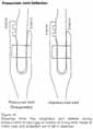
During stacking operations at the launch site, four segments are assembled to form the Solid Rocket Motor. The resulting joints are referred to as field joints, located as depicted in Figures 8 and 13. Joint sealing is provided by two rubber O-rings with diameters of 0.280 inches (+0.005, -0.003), which are installed, as received from Morton Thiokol, during motor assembly. O-ring static compression during and after assembly is dictated by the width of the gap between the tang and the inside leg of the clevis. This gap between the tang and clevis at any location after assembly is influenced by the size and shape (concentricity) of the segments as well as the loads on the segments. Zinc chromate putty is applied to the composition rubber (NBR) insulation face prior to assembly. In the assembled configuration the putty was intended to act as a thermal barrier to prevent direct contact of combustion gas with the O-rings. It was also intended that the O-rings be actuated and sealed by combustion gas pressure displacing the putty in the space between the motor segments (Figure 14). The displacement of the putty would act like a piston and compress the air ahead of the primary O-ring, and force it into the gap between the tang and clevis. This process is known as pressure actuation of the O-ring seal. This pressure actuated sealing is required to occur very early during the Solid Rocket Motor ignition transient. because the gap between the tang and clevis increases as.....
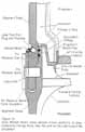
[58] ....pressure loads are applied to the joint during ignition. Should pressure actuation be delayed to the extent that the gap has opened considerably, the possibility exists that the rocket's combustion gases will blow by the O-ring and damage or destroy the seals. The principal factor influencing the size of the gap opening is motor pressure; but, gap opening is also influenced by external loads and other joint dynamics. The investigation has shown that the joint sealing performance is sensitive to the following factors, either independently or in combination:
(a) Damage to the joints/seals or generation of contaminants as joints are assembled as influenced by:
- (1) Manufacturing tolerances.
- (2) Out of round due to handling.
- (3) Effects of reuse.
(b) Tang/clevis gap opening due to motor pressure and other loads.
(c) Static O-ring compression.
(d) Joint temperature as it affects O-ring response under dynamic conditions (resiliency) and hardness.
(e) Joint temperature as it relates to forming ice from water intrusion in the joint.
(f) Putty performance effects on:
- (1) O-ring pressure actuation timing.
- (2) O-ring erosion.
The sensitivity of the O-ring sealing performance to these factors has been investigated in extensive tests and analyses. The sensitivity to each factor was evaluated independently and in appropriate combinations to assess the potential to cause or contribute to the 51-L aft field joint failure. Most of the testing was done on either laboratory or subscale equipment. In many cases, the data from these tests are considered to be directly applicable to the seal performance in full scale. However, in some cases there is considerable uncertainty in extrapolating the data to full-scale seal performance. Where such is the case, it is noted in the following discussions.
Assembly Damage/Contamination
It is possible that the assembly operation could influence joint sealing performance by damaging the O-rings or by generating contamination. The shapes of the solid rocket segments which include the tang and clevis, are not perfect circles because of dimensional tolerances, stresses, distortions.....
[59] ....from previous use, and the effects of shipping and handling. The most important effect is from the load of propellant, a plastic and rubbery material, which can take a set that relaxes very slowly. For example, since the segments are shipped in a horizontal position on railroad cars, their weight can make them somewhat elliptical-a shape they can maintain for some time. At assembly, after the lower segment (with the clevis on top) is placed vertically, the tang of the next segment is lowered into it. To make the fit easier, the upper segment is purposely reshaped by connecting the lifting crane in an appropriate position and, on occasion (51-L was one of these), directly squeezing the tang section with a special tool. To monitor the fit, the diameters of the clevis, DC, and the tang, DT (Figure 15) are measured at six positions 30 degrees apart, and difference of these measurements (DT - DC are noted. When these differences are such that the tang encroaches somewhat into the outer clevis, slanted edges (chamfers) permit the pieces to slide together. If the difference is too great, flat areas of the tang meet flat areas of the clevis. What really counts, of course, are differences of radii, which diameter measurements alone do not determine, for one does not know during the assembly how far off the centers are. This is a circumstance to be avoided, but one that can be detected during assembly. Experience has shown that a diameter difference of less than + 0.25 inches usually permits assembly without a flat-on-flat condition arising. A negative diameter difference means the tang encroaches on the inside of the clevis. The possibility was noted that contaminants from sliding metal and direct O-ring pinching might occur if this overlap is large. If it is too great, a flat-on-flat condition can arise inside the joint where it is very difficult to see. These dimensions shift as the pieces slide together and they change further as the propellant stresses relax during the period between assembly and launch. Therefore, a condition such as that which occurred during assembly of the aft segment for flight 51-L, wherein the maximum interference between tang and clevis at the O-rings was at approximately 300 degrees, may or may not have persisted until launch-seven weeks after assembly.
The O-rings are heavily greased to prevent damage. This grease adds another element of uncertainty to the configuration and action of the seal under pressurization, especially at low temperatures.
Testing was conducted during the investigation to evaluate the potential for assembly damage and contaminant generation, and its effect on seal performance. A sub-scale section of a field joint was configured in a test fixture and simulated assembly operations were conducted. This section was much stiffer than the full-scale booster segments and did not fully simulate actual assembly conditions. However, under these test circumstances, metal slivers were generated during situations wherein the tang flat overlapped the flat end of the clevis leg by 0.005 to 0.010 inches. The metal slivers in turn were carried into the joint and deposited on and around the O-rings. A second finding from this test series was that the O-ring section increased in length as the tang entered the clevis and compressed the O-ring diameter. The implication of this finding is that canted tang entry in a full diameter segment, while unlikely, could chase the O-ring around the circumference, resulting in gathering (bulging from the groove) on the opposite side. This could make the O-ring more vulnerable to damage. There is no known experience of such bulging during previous assemblies.
To understand the effects of potential contaminants on sealing performance, tests were conducted employing metal contaminants simulating those generated in the segment assembly tests. The tests were to determine if joints with metal shavings positioned between the O-ring and sealing surface could pass a static leak check but fail under dynamic conditions. The contaminants that passed the 50 pounds per square inch leak check were between 0.001 and 0.003 inches thick. Testing to determine seal performance under dynamic conditions with these representative contaminations is not complete. However, the possibility cannot be dismissed that contamination generated under some assembly conditions could pass a leak check and yet cause the seal to leak under dynamic conditions.
A second concern was structural damage to the clevis due to abnormal loading during assembly. An analysis was made to determine the deflections and stresses experienced during assembly of the right Solid Rocket Motor aft center segment to the aft segment. These stresses were then used in a fracture mechanics analysis of the O-ring groove to determine the maximum flaw size that would not fail under the 51-L case segment life cycle history. Included in this analysis was the single point load needed to deflect a suspended [60] segment to the side by 0.200 inches, and the maximum stress on the case clevis that this causes. The analysis further addressed a condition that has been encountered, where the tang sits on top of the inner clevis leg on one side and slips down into the clevis groove on the opposite side.
The result of this analysis is that the stresses induced during the operation were low and would not have resulted in hardware damage. Also, the stresses would have resulted in significant growth of an undetected flaw, which then would be detectable by inspection on its next use.
Gap Opening
The gap to be sealed between the tang and the inside leg of the clevis opens as the combustion gas pressure rises. This gap opening was calculated as a function of pressure and time by an analysis that was calibrated to joint deflections measured on a structural test article. The analysis extended the results beyond test calibration conditions to include propellant effects and external loads. The initial static gap dimensions combined with the time history of the gap opening determined the minimum and maximum gap conditions used for testing the capability of the O-rings to seal.
The joint deflection analysis established time histories for gap openings for primary and secondary O-rings for all field joints. For the aft field joints these data indicate gap opening increases of approximately 0.029 inches and 0.017 inches for the primary and secondary O-rings respectively. These values were used for sub-scale dynamic tests. Due to differences in motor pressure and loads, the gap opening increases for forward field joints are approximately 0.008 inches greater than for the aft field joints. Gap opening changes (called delta gap openings) versus time are shown in Figure 17 for the aft field joints. The total gap at any time also depends on the initial static gap, on rounding effects during segment pressurization, and on loadings due to struts and airloads. Sub-scale tests were run containing combinations of the above variables, but did not include the effects of the struts and airloads.
 |
|
 |
|
|
|
O-Ring Compression at Launch (Static)
As noted previously, diameters measured just prior to assembly do not permit determination of conditions at launch because, among other things, the propellant slowly relaxes. For STS 51-L, the difference in the true diameters of the surfaces of tang and clevis measured at the factory was 0.008 inches. Thus, the average gap at the O-rings between the tang and clevis was 0.004 inches. The minimum gap could be somewhat less, and possibly metal-to-metal contact (zero gap) could exist at some locations.
During the investigation, measurements were made on segments that had been refurbished and reused. The data indicate that segment circumferences at the sealing surfaces change with repeated use. This expectation was not unique to this joint.
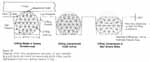
Recent analysis has shown and tests tend to confirm that O-ring sealing performance is significantly improved when actuating pressure can get behind the entire face of the O-ring on the upstream side of the groove within which the O-ring sits (Figure 18). If the groove is too narrow or if the initial squeeze is so great as to compress the O-ring to the extent that it fills the entire groove and contacts all groove surfaces, pressure actuation of the seal could be inhibited. This latter condition is relieved as the joint gap opens and the O-ring attempts to return to its uncompressed shape. However, if the temperature is low, resiliency is severely reduced and the O-ring is very slow in returning towards its original shape. Thus, it may remain compressed in the groove, contact all three surfaces of that groove, and inhibit pressure actuation of the seal. In addition, as the gap opens between the O-ring and tang surface allowing pressure bypass, O-ring actuation is further inhibited.
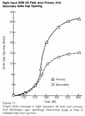
Two sub-scale dynamic test fixtures were designed and built that simulated the initial static gap, gap opening rate, maximum gap opening and ignition transient pressures. These fixtures were tested over a temperature range with varying initial static gap openings. A summary of results with initial gap openings of 0.020 and 0.004 inches is provided in Figure 19. The results indicate that with a 0.020-inch maximum initial gap, sealing can be achieved in most instances at temperatures as low as 25 degrees Fahrenheit, while with the 0.004-inch initial gap, sealing is not achieved at 25 degrees Fahrenheit and is marginal even in the 40 and 50 degree Fahrenheit temperature range. For the 0.004-inch initial gap condition, sealing without any gas blow-by, did not occur consistently until the temperature was raised to 55 degrees Fahrenheit. To evaluate the sensitivity to initial gap opening, tour tests were conducted at 25 degrees Fahrenheit with an initial gap of 0.010 inch. In contrast to the tests at a 0.004 inch gap, these tests resulted in sealing with some minimal O-ring blow-by observed during the sealing process.
These tests indicate the sensitivity of the O-ring seals to temperature and O-ring squeeze in a joint with the gap opening characteristics of the Solid Rocket Motors.
It should be noted that the test fixture placed....
.....the O-rings at a specific initial gap and squeeze condition uniformly around the circumference. It is not certain what the effect of differences in circumferential gaps might be in full size joints. Such effects could not be simulated in the subscale test results reported above.
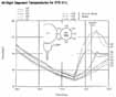
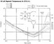
Joint Temperature
Analyses were conducted to establish STS 51-L joint temperatures at launch. Some differences existed among the six 51-L field joints. The joints on the right Solid Rocket Motor had larger circumferential gradients than those on the left motor at launch. It is possible that the aft field joint of the right Solid Rocket Booster was at the lowest temperature at launch, although all joints had calculated local temperatures as low as 28 +/- 5 degrees Fahrenheit. Estimated transient temperature for several circumferential locations on the joints are shown for the right Solid Rocket Motor aft field joint and the left motor aft field joint in Figures 20 and 21. These data are representative of other joints on the respective Solid Rocket Motors.
The investigation has shown that the low launch temperatures had two effects that could potentially affect the seal performance: (1) O-ring resiliency degradation, the effects of which are explained above; and (2) the potential for ice in the joints. O-ring hardness is also a function of temperature and may have been another factor in joint performance.
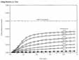
Consistent results from numerous O-ring tests have shown a resiliency degradation with reduced temperatures. Figure 23 provides O-ring recovery from 0.040 inches of initial compression versus time. This shows how quickly an O-ring will move back towards its uncompressed shape at temperatures ranging from 10 to 75 degrees Fahrenheit. When these data are compared with the gap openings versus time from Figure 17, it can be seen that the O-rings will not track or.....
|
|
|
|
|
|
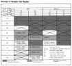
[64] Field Joint Distress
|
Flight |
|
|
|
|
|
|
|
. | ||||||
|
STS-2 |
AFT |
RH |
090 |
70 |
none/none |
Erosion |
|
41-B |
FWD |
LH |
351 |
57 |
1/none |
Erosion |
|
41-C |
AFT |
LH |
n/a |
63 |
1/1 |
O-ring heat |
|
41-D |
FWD |
RH |
275/110 |
70 |
2/none |
Erosion |
|
51-C |
FWD |
LH |
163 |
53 |
1/none |
Erosion |
|
51-C (3) |
MID |
RH |
354 |
53 |
1/1 |
Erosion |
|
61-A |
MID |
LH |
36-66 |
75 |
none/none |
Blow-by |
|
61-A |
AFT |
LH |
338/018 |
75 |
none/none |
Blow-by |
|
61-C |
AFT |
LH |
154 |
58 |
1/none |
Erosion |
|
51-L |
AFT |
RH |
307 |
28 |
1/2 |
Flame |
.....recover to the gap opening by 600 milliseconds (gap full open) at low to moderate temperatures. These data show the importance of timely O-ring pressure actuation to achieve proper sealing.
It is possible that water got into some, if not all STS 51-L field joints. Subsequent to the Challenger accident, it was learned that water had been observed in the STS-9 joints during restacking operations following exposure to less rain than that experienced by STS 51-L. It was reported that water had drained from the STS-9 joint when the pins were removed and that approximately 0.5 inch of water was present in the clevis well. While on the pad for 38 days, STS 51-L was exposed to approximately seven inches of rain. Analyses and tests conducted show that water will freeze under the environmental conditions experienced prior to the 51-L launch and could unseat the secondary O-ring. To determine the effects of unseating, tests were conducted on the sub-scale dynamic test fixture at Thiokol to further evaluate seal performance. For these tests, water was frozen downstream of the secondary O-ring. With ice present, there were conditions under which the O-ring failed to seal.
Putty Performance
The significance of the possibility that putty could keep the motor pressure from promptly reaching the O-rings to pressure actuate and seal them was apparently not fully appreciated prior to the Challenger accident. During the investigation, it became evident that several variables may affect the putty performance and, in turn, seal performance. However, limited test data and lack of fidelity in full scale joint simulation prevented a complete engineering assessment of putty performance. Tests were conducted over a range of putty conditions, including temperature at ignition, pretest conditioning to simulate the environmental effects, and dimensional variations within the joint. These test results demonstrated that putty performance as a pressure seal is highly variable. The results may be interpreted to indicate that the putty can maintain pressure during the ignition transient and prevent O-ring sealing. For example, one test conducted with putty, which had been conditioned for 10 hours at 80 percent relative humidity and 75 degrees Fahrenheit, delayed the pressure rise at the primary O-ring for 530 milliseconds at a....
.....temperature of 75 degrees. Tests at 20 degrees Fahrenheit with similarly conditioned putty delayed the pressurization time by 1.9 seconds. Such delays would allow full joint gap opening before a seal could pressure actuate.
To evaluate this effect, a sub-scale test fixture was fabricated that effectively simulated gap opening at the time of putty rupture and pressure application. The tests simulate the O-ring pressure actuation delay due to the putty temporarily holding the motor pressure. They were conducted over a range of temperatures, putty rupture time and initial O-ring squeeze. Test results (Appendix L, Fig. 6.5.1) demonstrated that sealing performance is dependent on temperature and initial squeeze, both of which affect the pressure actuation capability of the O-rings. The tests indicate that sealing capability is marginal for maximum squeeze conditions, i.e., a 0.004-inch gap, at 50 degrees Fahrenheit with a pressure delay of 500 milliseconds. For the temperature and O-ring squeeze conditions that existed for several of the STS 51-L field joints, O-ring sealing was not achieved in these tests with simulated putty rupture times delayed to 250 to 500 milliseconds.
Note that the sub-scale tests do not faithfully reproduce what happens in the real joint. These data do indicate, however, that the potential exists for O-rings not to seal as a result of variables related to the putty.
The seal is checked by pressurizing the volume between the primary and secondary O-rings. This action seats the secondary seal and drives the primary seal upstream into its groove. Because of concern that the putty could mask a leaking primary seal, the pressure was first increased from [66] 50 psi to 100 psi and then to 200 psi. The consequence of increasing the pressure is shown below.
|
. |
|
|
|
|
. | |||
|
Field Joint |
|
|
|
|
|
|
| |
|
|
|
| |
|
Nozzle joint |
|
|
|
|
|
|
| |
|
|
|
| |
Clearly the increased pressure used in the leak check increased the likelihood of a gas path through the putty to the primary seal. That is, with increased pressure, blow holes in the putty are more likely with a resulting greater potential for erosion damage to the O-ring. On the positive side the blow holes tend to prevent the delay in pressurization discussed in the previous paragraphs. This further illustrates the influence of putty variables on the performance of the Solid Rocket Motor seals.
The Dynamic Characteristics of the Field Joint Seal
The discussion of static factors which affect joint performance is based on the assumption that motor segments remain perfectly round, and that stacked segments are always a perfectly straight column. At launch the boosters are subjected to forces which bend and twist them. These forces cause physical changes in the shape of the boosters, actually squashing them out-of-round and bending them along their entire length. The dynamic effects of this out-of-roundness are most significant just after booster ignition when the hold-down bolts have been released because in the previous 6.6 seconds the boosters have actually been bent forward by the thrust from the main engines. The elastic energy stored in the entire system is then released, inducing a bending vibration in the boosters. This bending causes the case to change its shape from circular to elliptical, the maximum out-of-roundness occurring on the 045-315 degree line on the outside of the right booster. This deflection is a consequence of a vibration and occurs at a frequency of about 3 cycles per second. The same occurs in the left booster, only the deflection axis is oriented differently, being a mirror image of that which takes place in the right side. The dynamic effects cause an increase in the joint rotation, and, hence, increase the gap between the tang and clevis by about 10 percent. Another dynamic load results from the geometry of the struts which attach the booster to the external tank. Strut P 12 is attached to the booster at about the 314 degree point and imposes additional inertial forces on the booster which tend to additionally increase the gap by 10 to 21 percent.
Analysis of the Wreckage
The investigation of the sequence of events that led to the final breakup of the Challenger rests upon three primary sources of data: launch photographs, telemetry and tracking data, and the recovered pieces of the Shuttle wreckage. The third source of data is presented here, which is largely descriptive. It provides support for the conclusions reached through use of the data from the other two sources. A more detailed analysis that provides technical details to be used for subsequent redesign or accident analysis is available in the appendix.
Figure 24 shows an overview of the search areas with the general location of parts of both the left and the right Solid Rocket Boosters indicated. The area is at the edge of the Gulf Stream in water depth that ranged from 100 to 1,200 feet. Pertinent pieces were examined by use of a remotely controlled submarine containing a flood light and a television camera. The television picture was available on ship board and was transmitted to Kennedy and to Marshall. The arrangement allowed a number of people who were familiar with the Solid Rocket Booster to comment upon the merit of recovering a particular piece.
The aft left side of the Orbiter contained its original paint markings and showed no apparent sign of heat damage (photo A. All photo references are to color section, pp. 74-81). Thermal distress, however, was apparent on the right rudder speed brake panel and elevon (photo B). The paint was scorched and blackened on the right side panels of the aft part of the fuselage and vertical fin. The remaining recovered parts of the Orbiter did not seem to be affected by a hydrogen fire. The bottom side of the right wing showed some indentation on the tiles that make up the Thermal Protection System. This indentation was.....
....consistent with impact with the right booster as it rotated following loss of restraint of one or more of its lower struts.
The frustum of the nose cone of the right Solid Rocket Booster was damaged (photo E) as if it had struck the External Tank, but there were no signs of thermal distress. The frustum of the nose cone of the left Solid Rocket Booster (photo F) was essentially undamaged.
A substantial part of the External Tank was recovered. Analysis of this recovered structure showed some interesting features. Interpretation of the photographs suggests that the flame from the right hand Solid Rocket Booster encircled the External Tank. A short time later the dome at the base of the External Tank was thought to break free. Since the internal pressure of the liquid hydrogen tank is at approximately 33 pounds per square inch, a sudden venting at the aft section will produce a large initial thrust that tails off as the pressure drops. The intertank region of the wreckage contained buckling in the fore and aft direction consistent with this impulsive thrust. Similarly, the right side of the intertank showed signs of crushing. This crushing is consistent with the rotational impact of the frustum of the right Solid Rocket Booster with the External Tank following complete loss of restraint at the aft lower strut attachment area.
The telemetered signals from the rate gyros in the right Solid Rocket Booster clearly show a change in angular velocity of the booster with respect to the Orbiter. It is believed that this velocity change was initiated by a failure at or near the P12 strut connecting the booster to the External Tank. Photographs of the flight could not define the failure point and none of the connecting struts to the right Solid Rocket Booster or the corresponding area on the External Tank in this region were recovered. Therefore the exact location of initial separation could not be determined by the evidence. At the time of relative booster movement, the hole in the shell of the right Solid Rocket Booster was calculated to be six to eight inches in diameter located 12 to 15 inches forward and adjacent to the P12....
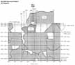
....strut. This location was within the center of the burned out zone on the right Solid Rocket Booster (photo G). As a matter of interest, the P12 strut is located close to the point on the circumference where the booster case experiences maximum radial deflection due to flight loads. It seems likely that the plume from the hole in the booster would impact near the location of the P12 strut connection and the External Tank. Using geometric considerations alone suggests this strut separated from the External Tank before it separated from the right hand Solid Rocket Booster.
Figure 25 shows a sketch of an interior unrolled view of the aft part of the right hand Solid Rocket Booster with the recovered burned pieces 131 and 712 noted. The critical region is between parts 131, the upper segment tang region, and part 712, the lower clevis region of the joint. This burned area extends roughly from station 1476, in the upper section, to 1517 on the lower region. In a circumferential direction (see figure 26) the lower end of the eroded region extends from roughly 291 degrees to 320 degrees and the upper eroded section extends between 296 and 318 degrees. Note that the region at about 314 degrees includes the attachment region of the strut to the attachment ring on the right Solid Rocket Booster.
Some observations were made from a detailed examination of the aft center section of the joint, contact 131. This piece (photo I) shows a large hole that is approximately centered on the.....
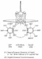
...307-degree circumferential position. Although irregular, the hole is roughly rectangular in shape, extending approximately 27 inches circumferentially along the tang (296 to 318 degrees) with total burnout extension approximately 15 inches forward of the tang. At either side in the interior of the hole (photo K) the insulation and steel case material showed evidence of hot gas erosion that beveled these surfaces (indicative of combustion products flowing through the hole from the interior of the Solid Rocket Motor). The top surface of the hole was hardly beveled at all. The tang O-ring sealing surface next to either side of the hole showed distinct erosion grooves starting from the O-ring locations (photo J). These erosion grooves indicate the O-rings were sealing the joint away from the central area during the later stages of the trajectory. No other evidence of thermal distress, melting or burning was noted in the tang section of the joint.
The part of the aft section of the right Solid Rocket Booster in the circumferential position of the hole was recovered (photos L and N). This piece, contact 712, showed evidence of a burned hole edge extending from 291 degrees to 318 degrees, approximately 33 inches long (see bracket, photo L). The burned surface extended into the aft attach stub region of the case adjacent to the P 12 strut attach point. The box structure of the aft attachment ring was missing from the attach stubs. The piece displayed fractures which led circumferentially or aft from the hole and the burned surface. Booster pieces on either side have not been recovered. Thus in the burn area no portion of the clevis or attachment ring other than the stubs was available for examination .
The exterior surface of the aft case piece also contained a large heat affected area (photo M). The shape and location of this area indicates a plume impingement from the escaping gases. The light colored material at the downstream edge of the area is probably asbestos from the insulator. The rust colored line more or less parallel to the stubs may be a stagnation line produced in the gas flow when the gases passed around the attachment ring. Secondary flow of metal from the aft attach stub ring also shows this feature. There was a small burn hole in the case wall (arrow, photo O) which appeared to have penetrated the case from the exterior toward the interior. This may also have been due to a swirling flow of hot gases within the attachment ring box structure. The shadow of the insulation downstream of the attach box can also be seen. This evidence suggests strongly that a hot gas plume impinged against the attachment ring, passed around and through it, and ultimately destroyed its structural integrity, probably late in the flight of the Solid Rocket Booster.
The photographs L, M, N, and O view the lower case piece in the inverted position. A correct orientation of this piece is shown in a composite view of the burn area located in photo P.
[70] Findings
1. A combustion gas leak through the right Solid Rocket Motor aft field joint initiated at or shortly after ignition eventually weakened and/or penetrated the External Tank initiating vehicle structural breakup and loss of the Space Shuttle Challenger during STS Mission 51-L.
2. The evidence shows that no other STS 51-L Shuttle element or the payload contributed to the causes of the right Solid Rocket Motor aft field joint combustion gas leak. Sabotage was not a factor.
3. Evidence examined in the review of Space Shuttle material, manufacturing, assembly, quality control, and processing of nonconformance reports found no flight hardware shipped to the launch site that fell outside the limits of Shuttle design specifications.
4. Launch site activities, including assembly and preparation, from receipt of the flight hardware to launch were generally in accord with established procedures and were not considered a factor in the accident.
5. Launch site records show that the right Solid Rocket Motor segments were assembled using approved procedures. However, significant out-of-round conditions existed between the two segments joined at the right Solid Rocket Motor aft field joint (the joint that failed).
a. While the assembly conditions had the potential of generating debris or damage that could cause O-ring seal failure, these were not considered factors in this accident.
b. The diameters of the two Solid Rocket Motor segments had grown as a result of prior use.
c. The growth resulted in a condition at time of launch wherein the maximum gap between the tang and clevis in the region of the joint's O-rings was no more than .008 inches and the average gap would have been .004 inches.
d. With a tang-to-clevis gap of .004 inches, the O-ring in the joint would be compressed to the extent that it pressed against all three walls of the O-ring retaining channel.
e. The lack of roundness of the segments was such that the smallest tang-to-clevis clearance occurred at the initiation of the assembly operation at positions of 120 degrees and 300 degrees around the circumference of the aft field joint. It is uncertain if this tight condition and the resultant greater compression of the O-rings at these points persisted to the time of launch.
6. The ambient temperature at time of launch was 36 degrees Fahrenheit, or 15 degrees lower than the next coldest previous launch.
a. The temperature at the 300 degree position on the right aft field joint circumference was estimated to be 28degrees +/- 5 degrees Fahrenheit. This was the coldest point on the joint.
b. Temperature on the opposite side of the right Solid Rocket Booster facing the sun was estimated to be about 50 degrees Fahrenheit.
7. Other joints on the left and right Solid Rocket Boosters experienced similar combinations of tang-to-clevis gap clearance and temperature. It is not known whether these joints experienced distress during the flight of 51-L.
8. Experimental evidence indicates that due to several effects associated with the Solid Rocket Booster's ignition and combustion pressures and associated vehicle motions, the gap between the tang and the clevis will open as much as .017 and .029 inches at the secondary and primary O-rings, respectively.
a. This opening begins upon ignition, reaches its maximum rate of opening at about 200-300 milliseconds, and is essentially complete at 600 milliseconds when the Solid Rocket Booster reaches its operating pressure.
b. The External Tank and right Solid Rocket Booster are connected by several struts, including one at 310 degrees near the aft field joint that failed. This strut's effect on the joint dynamics is to enhance the opening of the gap between the tang and clevis by about 10-20 percent in the region of 300-320 degrees.
9. O-ring resiliency is directly related to its temperature.
a. A warm O-ring that has been [71] compressed will return to its original shape much quicker than will a cold O-ring when compression is relieved. Thus, a warm O-ring will follow the opening of the tang-to-clevis gap. A cold O-ring may not.
b. A compressed O-ring at 75 degrees Fahrenheit is five times more responsive in returning to its uncompressed shape than a cold O-ring at 30 degrees Fahrenheit.
c. As a result it is probable that the O-rings in the right solid booster aft field joint were not following the opening of the gap between the tang and clevis at time of ignition.
10. Experiments indicate that the primary mechanism that actuates O-ring sealing is the application of gas pressure to the upstream (high-pressure) side of the O-ring as it sits in its groove or channel.
a. For this pressure actuation to work most effectively, a space between the O-ring and its upstream channel wall should exist during pressurization.
b. A tang-to-clevis gap of .O04 inches, as probably existed in the failed joint, would have initially compressed the O-ring to the degree that no clearance existed between the O-ring and its upstream channel wall and the other two surfaces of the channel.
c. At the cold launch temperature experienced, the O-ring would be very slow in returning to its normal rounded shape. It would not follow the opening of the tang-to-clevis gap. It would remain in its compressed position in the O-ring channel and not provide a space between itself and the upstream channel wall. Thus, it is probable the O-ring would not be pressure actuated to seal the gap in time to preclude joint failure due to blow-by and erosion from hot combustion gases.
11. The sealing characteristics of the Solid Rocket Booster O-rings are enhanced by timely application of motor pressure.
a. Ideally, motor pressure should be applied to actuate the O-ring and seal the joint prior to significant opening of the tang-to-clevis gap (100 to 200 milliseconds after motor ignition).
b. Experimental evidence indicates that temperature, humidity and other variables in the putty compound used to seal the joint can delay pressure application to the joint by 500 milliseconds or more.
c. This delay in pressure could be a factor in initial joint failure.
12. Of 21 launches with ambient temperatures of 61 degrees Fahrenheit or greater, only four showed signs of O-ring thermal distress; i.e., erosion or blow-by and soot. Each of the launches below 61. degrees Fahrenheit resulted in one or more O-rings showing signs of thermal distress.
a. Of these improper joint sealing actions, one-half occurred in the aft field joints, 20 percent in the center field joints, and 30 percent in the upper field joints. The division between left and right Solid Rocket Boosters was roughly equal. Each instance of thermal O-ring distress was accompanied by a leak path in the insulating putty. The leak path connects the rocket's combustion chamber with the O-ring region of the tang and clevis. Joints that actuated without incident may also have had these leak paths.
13. There is a possibility that there was water in the clevis of the STS 51-L joints since water was found in the STS-9 joints during a destack operation after exposure to less rainfall than STS 51-L. At time of launch, it was cold enough that water present in the joint would freeze. Tests show that ice in the joint can inhibit proper secondary seal performance.
14. A series of puffs of smoke were observed emanating from the 51-L aft field joint area of the right Solid Rocket Booster between 0.678 and 2.500 seconds after ignition of the Shuttle Solid Rocket Motors.
a. The puffs appeared at a frequency of about three puffs per second. This roughly matches the natural structural frequency of the solids at lift off and is reflected in slight cyclic changes of the tang-to-clevis gap opening.
[72] b. The puffs were seen to be moving upward along the surface of the booster above the aft field joint.
c. The smoke was estimated to originate at a circumferential position of between 270 degrees and 315 degrees on the booster aft field joint, emerging from the top of the joint.
15. This smoke from the aft field joint at Shuttle lift off was the first sign of the failure of the Solid Rocket Booster O-ring seals on STS 51-L.
16. The leak was again clearly evident as a flame at approximately 58 seconds into the flight. It is possible that the leak was continuous but unobservable or non-existent in portions of the intervening period. It is possible in either case that thrust vectoring and normal vehicle response to wind shear as well as planned maneuvers reinitiated or magnified the leakage from a degraded seal in the period preceding the observed flames. The estimated position of the flame, centered at a point 307 degrees around the circumference of the aft field joint, was confirmed by the recovery of two fragments of the right Solid Rocket Booster.
a. A small leak could have been present that may have grown to breach the joint in flame at a time on the order of 58 to 60 seconds after lift off.
b. Alternatively, the O-ring gap could have been resealed by deposition of a fragile buildup of aluminum oxide and other combustion debris. This resealed section of the joint could have been disturbed by thrust vectoring, Space Shuttle motion and flight loads induced by changing winds aloft.
c. The winds aloft caused control actions in the time interval of 32 seconds to 62 seconds into the flight that were typical of the largest values experienced on previous missions.
Conclusion
In view of the findings, the Commission concluded that the cause of the Challenger accident was the failure of the pressure seal in the aft field joint of the right Solid Rocket Motor. The failure was due to a faulty design unacceptably sensitive to a number of factors. These factors were the effects of temperature, physical dimensions, the character of materials, the effects of reusability, processing, and the reaction of the joint to dynamic loading.
[73] References
 |
 |
|
| |
|
|
|
 |
|
|
| |
 |
|
|
|
|
|
| |
|
|
|
|
| |