|
SUBMITTED BY: |
---------------------------------------------- |
|
|
JOHN W. THOMAS, DEPUTY ACCIDENT ANALYSIS TEAM |
|
|
|
|
APPROVED BY: |
---------------------------------------------- |
|
|
J.R. THOMPSON, JR., LEAD ACCIDENT ANALYSIS TEAM |
The events surrounding the Space Shuttle Mission STS 51-L accident were principally derived from data retrieved electronically from the flight vehicle, ground based records, and photographic and video imagery. Additionally, other information was obtained from mathematical model reconstruction of the system response to certain external phenomena such as upper atmospheric winds acting upon the vehicle during its launch and ascent flight phase. These events, when chronologically ordered, constitute the "Timeline" of events used by all analysts throughout the Accident Analysis Team effort. The time reference selected is the elapsed time from issuance of the command to ignite the SRBs and is referred to as Mission Elapsed Time or MET.
The STS 51-L mission launch on January 28, 1986, at approximately 11:38 a.m. EST, proceeded normally through SSME startup and SRB ignition. The first anomaly noted was a small puff of smoke observed between the right SRB and the ET in a region near the SRM aft field joint. The smoke appeared to persist for a period between 0.678 seconds and 3.375 seconds. From this point onward to approximately 59 seconds, all systems appeared to perform within their design boundaries; however. there were significant vehicle attitude excursions and high thrust vector control (steering) system activity observed beginning at approximately 37 seconds. This high activity created by upper atmospheric wind gusts and planned maneuvers persisted through the time (59 seconds) when the vehicle was heavily loaded by dynamic pressure. At 58.788 seconds, a flame reappeared. emanating from the general region where the puff of smoke was observed near lift-off. This event occurred almost 5 seconds after the SRMs had experienced their expected chamber pressure reduction at approximately 54 seconds and the SRMs pressure was again rising. Within less than 2 seconds, at 60.004 seconds. the right SRM internal pressure began to diverge from that of the left SRM and did not rise as rapidly as normal. This correlated with a right SRM combustion gas leak. At 61 seconds. just over 2 seconds after the leak was observed, the well defined plume was observed to be deflected, indicating that the hot gas had contacted the ET. Photographic analysis indicated that the plume breached the tank and produced an LH2 leak at 64.660 seconds. the LH2 leak was confirmed 1.2 seconds later, at 66.8 seconds. when the tank pressurization system could no longer maintain its normal repressurization rate; and at 72.6 seconds. the tank pressure could no longer be maintained indicating that the leak path had significantly increased and was growing rapidly. At 72.2 seconds, the guidance system showed that right SRB motion was not the same as the Orbiter and left SRB indicating that the lower ET-to-SRB attachment strut was severed or was pulled loose from the ET. Additionally, during this timeframe. large steering commands and systems responses were observed and at approximately 73 seconds, both LH2 and LOX pressures to the SSME showed a significant drop. This was followed at 73.124 seconds by the appearance of a circumferential white pattern around the ET aft bulkhead suggesting tank LH2 structural failure: and 0.013 seconds later, at 713.137 seconds, vapor was observed at the inter-tank indicative of the LOX tank failing. LOX tank failure can be attributed to abnormal loads induced by either or both the right SRB action at the forward attach point or the propulsive forces created by LH2 tank aft bulkhead structural failure. LOX was then observed streaming along the ET. At 73.191 seconds, a flash was observed between the ET and Orbiter that was immediately followed by total vehicle structural breakup explosion at 73.213 seconds. Intermittent telemetry data were obtained until 73.6 seconds at which time the SSME had responded normally as expected to reduced propellant pressures. Both SRBs exited the vehicle breakup propulsively and continued to fly erratically until destroyed by Range Safety Command at 110. 25 seconds. Details regarding post structural breakup are contained in the Search, Recovery, and Reconstruction Team Report.
3.0. Anomalies/Significant Observations
The anomalies/significant observations relating to the STS 51-L accident were identified throughout the investigation from careful review of manufacturing and launch processing records, engineering analyses, telemetry flight data, photographic and video imagery, and personal observation. The anomalies/significant observations described below are listed in the order they occur in the mission preparation and flight sequence.
3.1. Assembly
Launch site records review showed that the right SRM aft field joint was mated per approved procedures. However, significant out-of-round (ovality) conditions existed at mating as illustrated in Figure 3.1.1. In order to mate the aft center segment to the aft segment, it was necessary to install an infrequently used tool to adjust the aft center segment diametrical shape. Even with use of the tool. the relative diameters of the two segments were such that the joint tang would interfere with the joint clevis inner leg and also with the sealing O-rings. The circumferential area of maximum interference was located at the 1200-3000 position of the joint as noted in Figure 3.1.2. The significance of this observation is detailed in subsequent sections of this report.
3.2. Cold Weather
The ambient temperature at the pad ground level in the 24 hours before the STS 51-L launch reached a low of 24°F at 7 a. m. EST. The ambient temperature at launch time, 11:38 a. m., was 36°F. This translated to 28°F minimum SRM temperature at launch. The flight with the next coldest SRM temperature, 51°F, was STS 51-C. These low overnight temperatures necessitated that KSC implement facility and equipment protection procedures which called for, among other measures, small continuous water flow rates in the pad Firex system. This free water froze and resulted in various ice accumulations on the pad structure and to a lesser degree on the left SRB.

[L6] 3.3. Water in SRM joint
Following the STS 51-L accident, launch site personnel reported that water was observed in SRM joints on one SRM from an earlier mission, STS-9. The presence of water, previously unrecorded, in the STS-9 joints was discovered while destacking one of the SRMs to exchange a motor nozzle. Water overcoming the grease barrier and entering the joint is not immediately detrimental unless its presence exists in combination with cold weather at launch. This combination could produce ice in the SRM joints that if positioned at or near the secondary 0-ring as depicted in Figure 3.3.1 could interfere with proper seal operation. The potential for water in the joints was present on STS 51-L since over 7 inches of rain fell while it was on the launch pad and all joints had some or all their circumferences below freezing.
3.4. Right SRB Smoke On Ignition
At 0.678 seconds, smoke was observed between the right SRB and the ET. Due to malfunction of the cameras with the best view of this area, the exact point of origin of the smoke was not visible. From other cameras, the smoke was first observed above the aft SRB field joint and moved in an upward direction. The smoke quantity appeared to increase incrementally at a rate of 3-4 puffs per second until 2.499 seconds. With increasing upward motion of the vehicle, the smoke was observed trailing off behind the vehicle. Smoke was last seen above the attach ring at 2.733 seconds and was last seen dissipating below the vehicle at 3.375 seconds. Through film analysis, considering ground winds and vehicle liftoff motion, the smoke was estimated to have originated in the circumferential sector between 270° and 310° on the SRB.
3.5. Turbulence
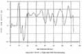
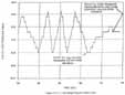
At approximately 37 seconds into the flight, STS 51-L encountered the first of several turbulent wind conditions which lasted until about 62 seconds MET. The effect of this turbulence produced by wind gusts was relatively large fluctuations in forces applied to the vehicle. This causes rapid attitude changes that were immediately sensed and corrected by the GN&C system. These corrections were not only to maintain the proper flight path but also position the vehicle to minimize certain loading conditions. These changes and corrections are of little significance unless they induce unusual loading conditions or cause the control system to exceed its design limit. The best portrayal of the turbulence experienced by STS 51-L is a graphical display of the product of aerodynamic pressure (Q) and vehicle side slip, B (yaw) [Greek letter beta] and angle of attack, a (pitch) [Greek letter alpha] versus speed and time. The early wind gusts were from the side in the yaw plane, Figure 3.5.1, whereas the later the Figure 3.5.2. were from the direction of flight in the pitch plane. The early yaw plane gusts were significant and at one time exceeded prior flight experience in the subsonic region. The pitch plane gusts were large and produced Qa [Greek letter alpha] values as large as - 4.200 PSF degrees. At two times in the flight, around 55 seconds and 68 seconds, Qa [Greek letter alpha] exceeded prior flight experience. Even though STS 51-L exceeded prior flight experience in both pitch and yaw planes, the maximum encountered were well within design limits.
3.6. Thrust Vector Control (TVC) Duty Cycle
The SRB TVC (steering) system responded properly to all routine commands and turbulence effects throughout the truncated mission; however, the turbulence effects caused the TVC system to be more active than was experienced on any prior flight. A graphical display of this high activity, Figure 3.6.1, is the angular movement of the SRB nozzle after about 35 seconds into the flight: the earlier movement was for the planned roll maneuver combined with any low altitude wind effects. Angular movements of this magnitude were experienced before, but, the character of high activity steering on STS 51-L differs from prior flights in that the number and rate or the excursions on STS 51-L were greater. This high activity is well within system capability and therefore would not normally produce loading conditions detrimental in any way to the vehicle structure. However, this activity could potentially have a deleterious effect if coupled with an anomalous condition that had previously weakened the structure. Specifically, if the smoke observed at lift-off was indicative of damage to the SRM joint, this large amount of steering could potentially have been associated with the flame observed originating on the right SRB at 58 seconds.
3.7. "Flashes"
Several "flashes" were noted in the SSME plumes and were initially included in the events timeline. The flashes or briefly visible streaks of light are quite common and were visible on other flights. Since the flashes are not peculiar to STS 51-L, they were removed from the event timeline.
3.8. Right SRB Flames
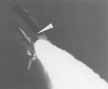
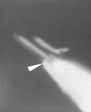
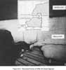
The first indication of the right SRB hot gas leak is listed on the timeline in section 2.0 as "first evidence of flame." This occurred at 58.788 seconds as a light visible between the right SRB and the ET, Figure 3.8.1. This light was observed to flicker briefly and then to grow in intensity and size until 59.262 seconds. The light was then masked by an increasingly large combustion product plume emanating from the side of the SRM. The flame location was determined using enhanced photography and computerized graphics to be very near the SRB aft field joint at approximately the 300° position.
3.9. Plume
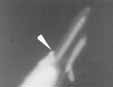
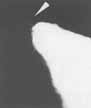
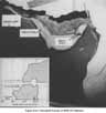
The plume emanating from the side of the SRM is characterized as continuous and well defined at 59.262 as shown in Figure 3.9.1. The plume continued to grow in size and at 60.238 seconds was evidently impinging on the ET due to the observed plume deflection. The plume continued to grow after that time until 64.660 seconds when there was an abrupt change in the character of the plume.
3.10. LH2 Tank Breach
The sudden change in the plume at 64.660 seconds was the first indication that the ET hydrogen tank had been breached, Figure 3.10.1. Cryogenic liquid hydrogen exiting the tank changed the flowfield and cooled the region where the plume was impinging on the ET. The plume was thus substantially changed which in some camera views appears as a sudden shrinkage. The hydrogen leakage was confirmed several seconds later through telemetered measurements of changes in the hydrogen tank pressure.
3.11. Right Aft SRB Strut Release
At 72.201 seconds, the lower attaching strut between the right SRB and the ET, Figure 3.11.1, released. Loss of this structural attachment, most likely caused by the strut pulling away from the hot gas-weakened hydrogen tank permitted the right SRB to rotate counterclockwise around the aft upper strut and the forward attachment at the inter-tank. This rotation is graphically displayed in Figure 3.11.2, indicated by divergent yaw and pitch rates between the left and right SRBs.
3.12. Drop in LH2 Tank Pressure
At 72.546 seconds, the ET hydrogen pressurization system could no longer compensate for the amount of hydrogen spilling from the aft tank area. Even with two flow control valves open to increase the amount of ullage pressurization gas, the pressure in the hydrogen tank began to decrease as shown in Figure 3.12.1.
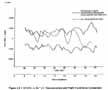
![Figure 3.5.2. STS 51-L (Q*a [Greek letter alpha]) Reconstruction and Flight Experience Comparison.](https://www.nasa.gov/wp-content/uploads/static/history/rogersrep/v2l8bs.jpg)


[L16] 3.13. Compressive Buckling E T Intertank - "Vapors" Emitting from Intertank
At 73.124 seconds. a circumferential white pattern was observed, Figure 3.13.1, on the + Z side of the ET aft dome. This was the beginning of hydrogen tank structural failure which released massive amounts of hydrogen from the aft tank area. A sudden large forward thrust resulted from this hydrogen expulsion which concentrated large compressive loads on the intertank where it joins the hydrogen tank. Either this abnormal loading condition or the effects of the right SRB rotation, possibly into the intertank, caused the intertank to fail. This in turn caused the LOX feedline and tank to structurally fail at 73.137 seconds as evidenced by the vapors appearing in the intertank region, Figure 3.13.2. This led directly to total vehicle structural breakup.
3.14. Recovered SRM Hardware
Both left and right SRM hardware fragments of varying sizes and locations were recovered during salvage operations. Two large pieces were retrieved that contained burned areas, Figures 5.4.1 and 5.4.2. They are confirmed by part and serial numbers and configuration features to be from the right SRM aft center and aft segments. The burned area spanned circumferential positions 291° to 318° at the right SRM field joint and measured approximately 33 inches circumferentially and 35 inches longitudinal]y. Additionally, the aft segment fragment contained a small hole, 1.5 inches by 4 inches located between the ET attach rings. Initial indication is that this small hole is a secondary effect from the large burned hole. The position of the large burned hole generally coincides with estimates of the smoke at lift-off and the observed flames on the right SRM at approximately 39 seconds.
3.15. SRM Field Joint/Seal Anomaly History
The anomaly records for all previous flights were researched to identify any past field joint/seal anomalies. The records showed nine joints on seven flights with O-ring anomalies tabulated in Figure 3.15. 1. The anomalies included combustion gas passing by the primary O-ring called blowby, primary O-ring erosion, and heat indications on both O-rings; but in no case did the joint leak.
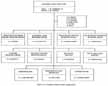
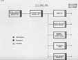
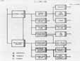
Immediately following the STS 51-L accident, working groups were activated to begin implementing predefined contingency procedures. Using immediately available flight data, visual observations, and photographic and video imagery, the working groups either identified possible faults that could originate in their respective flight element system and potentially led to the vehicle breakup of STS 51-L and/or they systematically examined flight data in search of any anomalous conditions that could cause the accident. The final disposition of flight elements is shown in Figure 4.0.1. The Orbiter. SSME, and Cargo were eliminated early in the investigation. Major areas of investigation for the External Tank and SRB are depicted in Figure 4.0.2. The Accident Analysis Team reviewed the assessment process and results for each element/fault to arrive at the conclusions and findings set forth below. The investigation concluded that the accident was initiated by a failure of the right SRM aft field joint which resulted in a hot gas leak.
4.1. External Tank (ET)
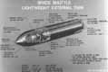
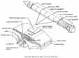
The ET is comprised of three primary structures: an L02 tank, an intertank, and an LH2 tank. The basic ET configuration is shown in Figure 4.1.1. In addition to the structures system, there are the propulsion system, electrical system, thermal protection system and interface hardware -all of which were considered initially in identifying possible faults or failures potentially contributing to the STS 51-L accident. The ET tank faults or failures that could have possibly contributed to the STS 51-L accident were:
Each fault or failure was assessed to determine its validity and possible implication in the events leading to the accident. A summary of each fault or failure and the Accident Analysis Team conclusions and findings are presented below.
a. ET Range Safety System
The possibility of the ET Range Safety System (RSS) prematurely detonating and destroying the ET and causing the accident was addressed; various failure modes were postulated such as aerodynamic overheating, electrical malfunction or premature arm and fire command. Assessment of all these modes found no credible failure mechanism associated with premature detonation of the ET Linear Shaped Charge (LSC). Additionally, large portions of LSCs from both the L02 and LH2 tanks were recovered intact, eliminating premature detonation as a possible cause. It is concluded that the ET RSS did not initiate the STS 51-L accident.
b. Structural Flaw
The possibility of a structural imperfection existing in either the pressurized or nonpressurized ET hardware elements, that could grow to a sufficient size to cause structure failure was examined in detail. All build paper, structural qualification test data, proof test inspection records, and x-rays, were re-reviewed and only one previously undetected imperfection was found: a 0.400-inch imperfection in the ET Station 2058 ring frame weld located on the + Z axis of the tank. This particular imperfection was found in recovered hardware with no propagation indicated. Other data from the Ice/Frost Team inspections, on-pad film and video coverage, pressurization records, and flight data revealed no leakage evidence. It is concluded that no imperfections existed that could have grown to a size to create a leak or cause catastrophic failure of the ET.
c. Overheating
The possibility of a structural failure due to overheating was addressed with several causes postulated: high heating due to abnormal trajectory, loss of TPS, hot gas leak from the SRM, and LH2 leak from the ET. The trajectory was normal until well after the SRM leak was observed at 58 seconds. Maximum aerodynamic heating does not occur until approximately 90 seconds, and at 73 seconds, heating was well within tank component structural capability. It is improbable that TPS was lost from any ET element based on reviewing prelaunch and flight films and analysis which indicated that TPS loss would not have resulted in structural failure over the first 60 seconds of flight. In addition the Ice/Frost Team observed no cracks or divots in the TPS during their walkdown 20 minutes before launch. Loss of TPS is not a viable contributor to the STS 51-L accident.
The possibility of a hydrogen leak resulting in overheating was addressed. Small leaks (0.0037 lb/sec) were determined by test to be visible. The Ice/Frost Team conducted an inspection at T-20 minutes and no leak was observed. To further test this leak hypothesis, if there were a LH2 leak at lift-off in the region where the SRM joint leak was later observed, it would probably be ignited by either the SRB ignition or SSME ignition and would ignite the SRB attach ring foam insulation. Tests have shown that this would produce copious quantities of dense black smoke and open flames. Smoke and flames in these quantities were not....
[L23] ....observed at lift-off nor anytime throughout the flight. Based on these data along with x-ray re-reviews and assessments which indicated that debris damage was improbable, it is concluded that a LH2 leak is improbable and that the cause for overheating the LH2 tank was SRM hot gases impinging on the ET aft end followed by burn through, leakage and ultimate breakup of the tank.
d. Damage at Lift-off
Possible damage to the LH2 tank at lift-off was considered. Prelaunch and lift-off photo analysis and TV monitoring showed no indication of debris contacting the tank; the Ice/Frost Team observed no leaks (vapors, frost). The LH2 vent arm retracted sufficiently and did not recontact the tank or SRB. No hazardous gas anomalies were observed. It is concluded that damage to the LH2 tank at lift-off is improbable and thus did not contribute to the ET structural breakup.
e. Load Exceedance
The possibility that abnormally high loads caused an ET structural failure was examined. Analysis indicated that there were no excessive loading conditions based on reconstructed lift-off and flight loads particularly between 30 seconds and 75 seconds. The maximum load produced was less than 80 percent of design allowables and therefore a structural failure is improbable. Additionally, the structural implication of vent and flow control valves operation was examined. Telemetered data showed as expected that both LO2 and LH2 vent valves were closed throughout flight. Flow control valves showed completely normal operations.
In the process of assessing the specific faults or failures, the accident investigation reviewed all build paper for the ET and found adequate and proper disposition of Material Reports Board (MRB) reports, weld repairs, Class I and II Design Changes, Discrepancy Reports (DRs), Problem Reports (PRs), liaison calls, MAF/KSC action requests, X-rays, and closeout photographs.
Conclusions and Findings
Based on this review and assessment, the Accident Analysis Team concludes that it is improbable that that the External Tank initiated the STS 51-L accident.
4.2. Space Shuttle Main Engine (SSME)
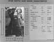
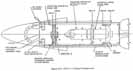
The SSME is comprised of a powerhead, two low pressure turbopumps, an expansion nozzle, a control computer, and five main propellant valves (Figure 4.2.1). All were considered initially in identifying possible faults or failures potentially contributing to the STS 51-L accident. The hot gas manifold is the major structural component of the powerhead to which are attached the main injector and combustion chamber, two high pressure turbopumps with preburners, an oxygen heat exchanger, the gimbal bearing, and thrust vector control actuator attach points. The SSME faults or failures that could have possibly contributed to the STS 51-L accident were:
Each fault or failure was assessed to determine its validity and possible implication in the events leading to the accident. A summary of each failure and the Accident Analysis Team's conclusions and findings are presented below:
a. Hard Start
A hard start could possibly put excessive loads into the vehicle structure during the start transient period. An in-depth review of the 60K bit data for all three engines showed the starts to all be nominal. A comparison of these start transients was made with the previous launches of the Challenger vehicle and no anomalies were found. Additionally engineering film of the start was reviewed and only the normal motion that is seen on every start was observed.
b. Noncontained Failure
A noncontained failure would cause vehicle damage. A thorough analysis of the data from all three engines showed that the engine performance was completely normal until influenced by decreased propellant inlet pressures. There were no anomalies detected by the instrumentation until after the ET structural breakup began. All three SSMEs were recovered and close examination revealed that they experienced a LOX rich shutdown as was indicated by flight data. Also, there was no evidence of' turbine-blade- induced damage during this severe shutdown sequence.
In the process of assessing the specific faults or failures, the accident investigation broadened to other aspects of the SSME. Review of all records pertaining to the manufacturing, acceptance, and prelaunch processing was completed. The review verified that: the as-built configuration of the flight engine set was as required by documentation; all deviations from the planned manufacturing procedure were properly dispositioned and acceptance testing and prelaunch processing were accomplished in accordance with the required procedures with anomalies properly dispositioned.
The previous flight history of the engine set and flight data from all previous flights were reviewed and compared well with flight data from STS 51-L. Engine performance was shown to be consistent with mission thrust profile requirements. All flight and postflight anomalies were properly dispositioned and documented by the Flight Readiness Review process.
Conclusions and Findings
Based on this review and assessment. the Accident Analysis Team concludes that it is improbable that the SSME initiated the STS 51-L accident.
4.3. Orbiter and Government Furnished Equipment
The Orbiter subsystems. Figure 4.3.1. include Propulsion and Power, Avionics, Structures, Thermal. Environmental Control and Life Support, Mechanical and Interface, and Government Furnished Equipment (GFE). Onboard GFE for this mission included the remote manipulator system, extravehicular mobility units, extravehicular activity hardware, television, worn equipment, storage provisions and communication equipment.
The Orbiter investigation consisted of a review of all Orbiter data retrieved from functional areas of the vehicle. The review was to assess system performance and identify any abnormal conditions which could have contributed to or resulted from the accident. Also reviewed were vehicle and GFE processing records and pre-mission analyses.
The review observation s/conclusion s are summarized below for each Orbiter subsystem.
a. Propulsion and Power
The Main Propulsion System (MPS) investigation was reported in the ET Working Group Final Report and indicated no anomalous conditions contributory to the accident relative to MPS.
All Orbital Maneuvering System (OMS) measurements (temperatures, pressures, events, commands and stimuli, and switch positions) were reviewed along with all General Purpose Computer (GPC) data relating to the OMS. There were no indications of anomalous behavior from any of the data. All temperature and pressure transducers active during ascent for the Reaction Control System (RCS) were reviewed, including thruster chamber pressure leak temperature, line temperature,....
[L26] ....propellant tank, helium tank, and propellant line transducers. Nothing was found that would have had an effect on the accident.
Auxiliary power Unit (APU) pressures. temperatures, speed. and vibration were reviewed, and no anomalous conditions were observed during ascent from these data. Selected hydraulic measurements, including system pressures fluid quantities and most temperatures in the aft compartment and in the wing cavity containing the elevon actuator supplies lines, were reviewed and found to have no anomalous behavioral indications. All fuel cells/Power Reactant Storage and Distribution (PRSD) subsystem measurements were reviewed and found to be normal during all phases of ground and flight operation prior to the accident. For pyrotechnic devices. all available firing control circuit measurements were reviewed, along with radiography of NASA standard devices, Orbiter/ET attachment bolt, and debris reports: all data were normal. All available data regarding batteries were reviewed. and no indications were found that the batteries were involved in initiating the accident.
b. Avionics
Data were reviewed relative to the ascent Guidance, Navigation and Control (GN&C) subsystems and it appears that the GN&C performed properly. All GN&C sensors, effectors, and software performed as designed until data loss occurred. The Inertial Measurement Unit (IMU) data from the preflight calibration through signal loss were found to be normal. All Data Processing System (DPS) related data were reviewed and nothing significant was found. Data associated with the Displays and Control (D&C) indicate all items were functioning normal. Data review of the Electrical Power Distribution and Control Subsystem indicated that its performance was normal until the time of the accident. All critical Communication and Tracking System parameters active during launch were evaluated and found to be normal. No instrumentation anomalies were observed during the prelaunch and launch period before signal loss.
c. Structures
Structures evaluation included relevant ground and flight data (loads, temperatures. pressures, and purge flows), hardware changes and discrepancy reports since the last OV-099 flight, and debris identification. The review of these data indicated that no Orbiter structural elements were contributory to the accident.
d. Thermal
Orbiter structural prelaunch temperature measurements were evaluated. Thermal data for STS 51-L were compared with those for STS 31-C, which represented the coldest prelaunch ambient temperatures previously experienced. All STS 51-L thermal data for the Orbiter systems were found to be within specified limits.
e. Environmental Control and Life Support
Data related to the Atmospheric Revitalization System were evaluated. During prelaunch, launch, and until signal loss, data indicated that both of the water coolant loops were normal, the pressure control system functioned normally, all fans functioned normally, and all switches, valves and talkbacks were configured properly.
The Active Thermal Control Subsystem related data were evaluated and during prelaunch, launch, and until loss of signal, data indicated that both of the freon coolant loops functioned normally, the ammonia boiler system was normal, and all switches, valves. and talkbacks were configured properly.
The Water Management Subsystem was evaluated and found to have functioned normally during all phases. The Smoke Detection and Fire Suppression Subsystem and Airlock Support Subsystem were found to have functioned normally during all phases. The Waste Collection Subsystem is normally inoperative during the launch phase, so no data were available.
f. Mechanical System and Interfaces
No anomalies were identified relative to any of the mechanical systems. The vent doors remained open throughout the launch. The payload bay doors remained latched. All landing gear, were up and locked, all doors remained closed and locked, and the remote manipulator system and payload retention system remained latched. Film and 01 data showed that there was no premature Orbiter/ET separation.
Video tapes and photographs indicated that the crew egress hatch, which caused the launch scrub on the preceding day remained properly closed.
g. Government Furnished Equipment
The onboard GFE configuration and prelaunch processing were reviewed and the GFE, was determined to have been flight-ready with no unusual or abnormal conditions that would have contributed to the accident.
Conclusions and Findings
Based on this review and assessment, the Accident Analysis Team concludes that it is improbable that the Orbiter and GFE initiated the STS 51-L accident.
4.4. Payload/Orbiter Interfaces
The payload/Orbiter interfaces are mechanical, structural, thermal, avionics, power, and fluid systems providing attachment or services from the Orbiter. Additional interfaces are those induced by the flight environment such as loads and thermal. The review of the payload/Orbiter interfaces focused on two primary areas:
An in-depth review of the STS 51-L impounded data, flight data, and analytical predictions was conducted to reverify the flight readiness of the cargo integration design and hardware. A reexamination of all payload safety hazard reports was also accomplished along with a comparison of the analysis and flight data from STS 51-L and other STS missions to identify discrepancies in the design or documentation. The payload closeout photographs and KSC work authorization documentation were reviewed to ensure compatibility with the engineering Figure 4.4.1 shows the STS 51-L payload configuration. A summary of these activities is presented below along with conclusions and findings:
a. Flight Readiness Assessment
Engineering drawings were reviewed to ensure that all cargo requirements were incorporated and that the cargo integration hardware design and implementing documents were compatible with mission requirements. The compatibility of requirements and documentation was verified and the payload safety reassessment confirmed that all payload elements were safety certified for flight.
An in-depth review of the payload integration hardware installed in OV-099 for STS 51-L was conducted at the part number/serial number level to determine the individual hardware pedigrees. The specific areas addressed in the review included hardware as-built versus as-designed post delivery modifications, certification status, cumulative flight usage, and configuration differences between the previous IUS/TDRS mission STS-6 and STS 51-L. All hardware was certified and its cumulative usage was well within the 100-flight certification. No significant differences were found between common hardware flown on STS-6 and STS 51-L.
An engineering analysis team re-reviewed the verification loads analysis for STS 51-L. The Orbiter/payload interface loads were.....
[L28]...compared for lift-off and ascent cases. Previously calculated high positive margins remained at the Orbiter/payload interfaces throughout the lift-off and ascent phases.
b. Flight Data Evaluation
Of the two major payloads. TDRS-B was the only one for which prelaunch and flight data were available. IUS had only prelaunch data. Certain seasons, externally mounted to the TDRS-B, such as those on the external thrusters and the solar array panels, showed approximately 1°F decrease in temperature, which is expected for small thermal mass components responding to expansion cooling of the payload bay air during ascent. All temperatures were as expected for the period from prelaunch through loss of signal.
The Orbiter data were available in real time and did not indicate any anomalous condition. Subsequently, the telemetry stream was analyzed, data frame by data frame. The detailed analysis confirmed the real-time data. The payload trunnions (IUS/TDRS and Spartan Halley) did not lose contact with the payload retention system microswitches an indication that the payload trunnions were in place and latched. The payload power monitors did not significantly vary, an indication that the electrical service to the payload did not lose continuity. The built-in test equipment associated with the IUS telemetry stream did not change state, an indication that the IUS telemetry stream did not lose lock or shift phase.
Rate gyro measurements from TDRS that were used to evaluate whether STS 51-L lift-off conditions were within design limits, were compared with STS-6 launch conditions. Results indicated that payload responses on STS 51-L were similar to those of STS-6 and were within design levels and prelaunch predictions.
Conclusions and Findings
Based on this review and assessment, the Accident Analysis Team concludes that payloads were properly integrated into the Orbiter, properly reviewed for flight readiness, and operated normally until the structural breakup. It is improbable that the payloads and the integration process contributed to the STS 51-L accident.
4.5. Inertial Upper Stage (IUS)
The IUS is a two-stage, solid- rocket-propelled, three-axis controlled, inertially navigated upper stage used to deliver spacecraft weighing up to approximately 5,000 pounds from the Shuttle parking orbit to geosynchronous orbit. The basic vehicle includes: stage structure; solid rocket motors and the reaction control subsystem for propulsion; avionics for Telemetry, Tracking and Command (TT&C), guidance, navigation and control, data management, and TVC; electrical power sources and electrical cabling; and airborne software. The IUS vehicle also provides the interface between the Tracking and Data Relay Satellite (TDRS) and the launch vehicle. The IUS-3 vehicle and Airborne Support Equipment (ASE) mated with TDRS-B is shown in Figure 4.5.1.
The assessment of the IUS-3 potential contribution to the STS 51-L accident centered around developing a credible fault tree incorporating inputs from safety hazard analysis reports and Failure Mode and Effects Analysis (FMEA). The fault tree identified three IUS scenarios as possible contributors:
Each failure scenario was assessed to determine its validity and possible contribution to the events leading to the accident. A summary of each fault and the Accident Analysis Team conclusions and findings are presented below.
a. Premature Ignition
Premature Ignition of either IUS-3 stage 1 and/or stage 2 motor while still in the Orbiter bay would result in a catastrophic failure of the Orbiter. An assessment of possible causes for premature ignition centered on three potential faults: (1 ) Electrostatic Discharge (ESD), (2) inadvertent ignition command. and (3) autoignition. Each of these would have been characterized by a rapid increase in the Orbiter payload bay temperature and pressure and would have been immediately followed by structural damage to the payload bay doors. The facts that the payload bay temperatures remained essentially constant, and that the Orbiter photographic and telemetry data indicated the payload doors remained closed and latched from lift-off until signal loss, verified that there was no pre-ignition of the SRMs.
b. Explosion/Fire
An IUS-3 component explosion/fire could have damaged critical systems in the Orbiter by overheating or impact. Five sources other than an IUS motor preignition were identified as potential origins of a fire or explosion in the payload bay: (1) release and ignition of IUS hydrazine from the RCS tanks, (2) fire or explosion from an IUS battery, (3) impact or rupture of a motor case and subsequent ignition of exposed propellant, (4) fire of electrical origin due to a short, and (5) fire or inadvertent ignition of pyrotechnic devices due to excessive Radio Frequency (RF) radiation. Release of propellant from the tanks was prohibited by dual failure tolerant system design and large safety factors (4). Thermal measurements in the propellant tank and in components adjacent to the propellant tanks indicated no anomalies. Prelaunch and thermal measurements in the Orbiter payload bay and in TDRS-B near the RCS were stable throughout the ascent period. A fire and/or explosion resulting in shrapnel from an IUS battery was eliminated based on prelaunch monitoring of open circuit voltages on all batteries, except the ASE batteries. Location of the ASE batteries made the damage potential to critical systems very small if these batteries burned or exploded. Motor case impact or rupture with resultant exposure and propellant ignition was categorized as improbable because batteries and RCS burning/explosion were eliminated by flight data analysis. They were the only potential IUS heating and high velocity shrapnel sources. Propellant burning was not indicated by payload bay thermal measurements. Electrical shorting was eliminated as a fire source in the payload bay because IUS-3 electrical and Orbiter voltage monitors were normal at launch and during STS 51-L ascent. Fires initiated by RF radiation due to inadvertent IUS, TDRS, or ground emittance were eliminated based on data analysis. These data showed IUS-3 and TDRS-B worst case RF radiation during ascent was less than ground emitted radiation to the payload bay during prelaunch checkout. Ground-emitted radiation during ascent was within specified limits.
c. Payload Shift
An IUS-3/TDRS-B payload shifting or breaking free within the Orbiter due to structural failure or premature separation was hypothesized as a possible cause of the STS 51-L accident. Such a shift could have resulted in severe Orbiter damage from a direct impact, or could have induced a significant shift in the STS vehicle center of gravity and possibly affected STS control. Four possible faults were considered which could have led to Orbiter damage or substantial payload shift: (1) IUS stage 2/TDRS separation, (2) IUS stage 1/stage 2 separation, (3) IUS/TDRS-B separation from ASE, and (4) IUS/ASE separation from Orbiter. All of these faults were eliminated because dynamic response data conclusively showed that the IUS-3/TDRS-B payload responded as predicted until the final data loss. The fact that TDRS-B data, which pass....

[L30]....through the IUS stage 1/stage 2 and ASE, were continuous through data loss verified that the elements did not separate.
A thorough IUS-3 hardware processing documentation review was conducted at the Boeing facility in Kent, Washington; the Eastern Launch Site (ELS), Cape Canaveral Air Force Station, Florida; and the Kennedy Space Center (KSC). There were no discrepancies in the data that would have led to any anomalous conditions on IUS-3.
Conclusions and Findings
Based on this review and assessment, the Accident Analysis Team concludes that it is improbable that the IUS initiated the STS 51-L accident.
4.6. Tracking and Data Relay Satellite (TDRS)
The TDRS spacecraft weighs approximately 4,905 pounds and is 9.5 feet in diameter and 19.5 feet long. The forward 11 feet contain six deployable appendages, two solar arrays, one Space Ground Link (SGL) antenna, and two single access antennas. The spacecraft body structure consists of a payload structure and a spacecraft structure. These structures house the Tracking and Telemetry and Command (TT&C) subsystem, power subsystem, thermal control subsystem, ordnance subsystem, Reaction Control Subsystem (RCS), and Attitude Control Subsystem (ACS).
Each subsystem was evaluated for performance of the TDRSB spacecraft in the prelaunch and launch phases and for possible contributions to the STS 51-L accident. A summary of the subsystems assessment and the Accident Analysis Team conclusions and findings are presented below:
a. Tracking, Telemetry and Command (TT&C) System
Telemetry data were transmitted from TDRS-B from approximately 48 hours prior to launch through signal loss. The telemetry system was functioning properly and the data analyzed from the TT&C subsystem indicated that the telemetry processor was in its normal operational mode and all power supply voltages and calibration voltages were normal. There were no changes through the countdown to the time of the structural breakup, when all telemetry abruptly halted. The TT&C subsystem command and tracking elements were inactive during the countdown through accent and no changes were noted, indicating that the TDRS-B spacecraft was not interrogated nor commanded in any way to alter its launch configuration. All data reviewed show proper operation of the TDRS-B TT&C subsystem and it is concluded that there were no anomalous operations.
b. Power Subsystem
While installed in the Orbiter. TDRS spacecraft receives power from the Orbiter through the IUS. The TDRS power subsystem had a total of 138 telemetry indications, the main data source used to determine the power subsystem activity. Analyzing this telemetry from the TDRS-B electrical power subsystem showed all subsystem elements were performing as expected from prelaunch through signal loss, There were no indications that the Orbiter-supplied power, through the IUS, experienced any problems; therefore, it is concluded that the TDRS power subsystem functioned normally.
c. Thermal Control Subsystem
The TDRS thermal control subsystem is designed to maintain proper temperatures primarily by passive means. Also, there is a thermostatically controlled heater system to ensure minimum required temperatures are maintained. The thermal subsystem was monitored by 82 configuration status indicators and 137 analog temperature channels. This telemetry showed that TDRSB remained in its nominal thermal configuration and experienced normal temperatures throughout prelaunch and signal loss. It is concluded that the data positively indicate all thermal subsystem activity on TDRS-B was normal.
d. Ordnance Subsystem
All ordnance devices on TDRS required three functions to be operated: an ARM function, an ENABLE function and a FIRE function. The ARM function is a hardwire-input from the IUS and has no RF-commandable backup. Without the ARM function occurring, the ENABLE and FIRE functions will not be effective. From a telemetry frame-by-frame analysis, the ordnance subsystem integrity was maintained until so close to the end of the mission that it is implausible to postulate that it contributed in any way to the accident. No indications were received that indicated IUS from TDRS separation occurred, that any deployable appendage ordnance had been fired, or any appendage motion had begun. It is concluded that no changes occurred in the ordnance subsystem which could have contributed to the STS 51-L accident.
e. Reaction Control Subsystem (RCS)
The RCS was inactive at launch and required an IUS discrete command and two ground commands to activate any propellant isolation valve. Telemetry indicated no valve actuation, changes in tank pressures or temperatures, nor propellant line temperature violations. There was no telemetry that would suggest a hydrazine leakage or abnormality and no indications that the TDRS RCS contributed to the STS 51-L accident.
f. Attitude Control Subsystem (ACS)
During the launch phase, the ACS was disabled except for the gyros and associated electronics necessary to provide the ACS telemetry status. All telemetry parameters reflecting ACS configuration remained normal and unchanged during the STS 51-L prelaunch and post-launch periods. The TDRS-B gyros tracked the STS Orbiter gyros closely except for what appeared to be some higher frequency aliasing and the possible modes induced by the cantilevered IUS/TDRS configuration with attendant mounting structures. Since all ACS data was as expected, it is concluded that the ACS did not contribute to the STS 51-L accident.
g. Structurally Mechanical Subsystem
The TDRS was mounted cantilevered from the IUS by an adapter ring that provided structural, communications, and power interfaces. Structural integrity loss indications would have to be observed by interruptions in telemetry or electrical power. TDRS telemetry during the launch phase was transmitted by hardline to IUS, and interleaved with Orbiter data. If separation had occurred at either the TDRS/IUS interface or the IUS/ASE interface, TDRS data would have stopped. There was no anomalous telemetry until signal loss of all vehicle telemetry. TDRS also received power from the Shuttle via the IUS through the same interfaces. There were no indications of TDRS batteries coming online, which would also indicate that structural integrity at the TDRS/IUS and IUS/ASE interfaces was maintained until the structural breakup. An inspection of the recovered debris gives four indications that the TDRS/IUS remained intact until the structural breakup. First, the separation band lanyards frayed at the end where they attach to the band, indicating that the spacecraft was pulled forcefully from the adapter. Secondly, the V-groove ring structure at the top of the adapter was torn from its riveted connection to the adapter, indicating that a strong shear existed between the spacecraft and IUS which would only be generated if the two were still attached. Thirdly, the adapter base was torn where it attached to the IUS, again indicating high tension and shear forces. Finally, the separation band (Marmann clamp) attaching the spacecraft to the TDRS IUS adapter has been recovered intact with the separation nuts unfired providing additional evidence that separation did not occur prior to structural [L31] breakup. In summary, there are no indications from telemetry or recovered debris which indicated that the structural integrity of the TDRS, or the TDRS/IUS interface, has been compromised.
The "as-performed" TDRS processing records at KSC were received for technical correctness and to verify that no open safety related issues existed. No information was uncovered to indicate that any unsafe conditions existed on TDRS or that any safety requirements had been violated or compromised.
Conclusions and Findings
Based on this review and assessment, the Accident Analysis Tears concludes that it is improbable that the TDRS initiated the STS 51-L accident.
4.7. Spartan Halley Payload
The Spartan program objective was to provide a means for flying sounding rocket-type experiments aboard the Space Shuttle by developing small experiment carriers which could be retrieved, refitted with new experiments, and reflown. The Spartan Halley payload and its location in the Orbiter are shown in Figure 4.7.1.
A review and assessment of Spartan Halley performance was conducted to establish any possible contributions to the STS 51-L accident. The Spartan Halley was unpowered except for the release engage mechanism latch monitor. Its current was in the order milliamps and the telemetry records obtained from the Orbiter indicated that the latches were in the proper configuration and thus Spartan Halley remained firmly attached during flight. In addition, the TDRS spacecraft data indicated there was no interraction from Spartan. Therefore, the Spartan Halley and its support structure remained intact. The payload bay temperature in the vicinity of Spartan was 55°F indicating no anomalous thermal conditions.
Conclusions and Findings
Based on this review and assessment, the Accident Analysis Team concludes that it is improbable that Spartan Halley initiated the STS 51-L accident.
4.8. Range Safety System
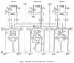
The RSS provides a means of flight termination of the SRB and ET by range safety ground commands transmitted by the range safety officer. The Space Shuttle RSS is a triplex configuration Figure 4.8.1) which has redundant circuits on each SRB and on the ET with the exception that the ET only has one Integrated Receiver Decoder (IRD). Redundancy is further provided by cross-strapping "Arm" and "Fire" commands received by either circuit on one SRB by hardwire to the other SRB. Any command ("Arm" or "Fire") received by either circuit on either SRB is cross-strapped to the ET RSS distributor. The IRD is the active element that implements the security measures of the RSS. A nonvolatile, solid state memory device is designed within the IRD. The IRD compares any received message to the code in memory for validation of the command. Prior to SRM ignition ground commands will activate all of the RSS by turning power ON as well as "Arming" the Safe and Arm (S&A) devices. The RSS is inhibited from executing either "Arm" or "Fire" commands from power ON until 10 seconds prior to SRM ignition. The Shuttle lifts off with the RSS active and ready. Before normal separation of the SRBs, the Orbiter will issue commands to "Safe- each SRB RSS. These commands cause the S&A devices to rotate to the "Safe" position and the SRB RSS power to be turned OFF, thereby providing for safety of the recovery crew. In case of abnormal separation of the SRBs or the ET, the RSS power will remain ON and the range safety ground transmission System will have access to the destruct functions.
It was initially postulated that the STS 51-L accident could have been triggered by premature actuation of the RSS. This potential fault or failure was assessed using flight data, observed events in the timeline, and recovered hardware. The flight data verified that the RSS was not erroneously commanded nor prematurely activated by a flight hardware failure. If a ground issued destruct-signal had been initiated, the SRBs would have been destroyed at the time of the accident along with the ET because the ET and SRB RSS circuits are electrically interconnected. The SRBs were subsequently destroyed by ground command after the accident and the LSCs from the ET LH2 and LO2, tanks were recovered and had not been fired.
Conclusions and Findings
Based on this review and assessment, the Accident Analysis Team concludes that it is improbable that the RSS initiated the STS 51-L accident.
4.9. Solid Rocket Booster (SRB)
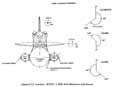
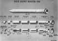
The SRB is comprised of seven subsystems; Structure, Thrust Vector Control (TVC), Range Safety, Separation. Electronics and Information, Recovery, and the SRM. The basic SRB configuration is shown in Figure 4.9.1. All subsystems were considered initially in identifying possible faults or failures potentially contributing to the STS 51-L accident.
The SRB faults or failures that could have possibly contributed to the accident were:
Each fault or failure, was assessed to determine its validity and possible implication in the events leading to the accident. A summary of each fault or failure and the Accident Analysis Team conclusions and findings are presented below:
a. Structural Overload
Reconstructed lift-off and flight loads were compared to design loads for all conditions to determine if a structural failure may have caused the accident. In all cases the SRB design capability bounded the STS 51-L loads experienced and was not a factor. Photographic and video imagery confirmed that both SRBs remained structurally intact until the time of the explosion except for the leak observed on the right SRB. Immediately preceding the ET structural breakup and explosion, there was an apparent loss of part of the aft attachment between the right SRB and the ET. This was a result of the impingement of the anomalous plume from the side of the right SRB on the aft attach ring area. Furthermore, this separation occurred several seconds after the first hydrogen leak from the ET was visible on photographic and video imagery. Thus, it is more likely that the ET attachment support failed rather than the strut itself.
b. Pressure Integrity Violation
Anomalies and observations described in section 3.0 indicated that the right SRM pressure integrity was violated at approximately 58 seconds. Photographic imagery enhancement and computerized graphic analysis placed the violation, a motor case hot gas leak, near the aft field assembly joint in the circumferential hemisphere adjacent to the ET. Early in the investigation it was postulated that the observed leak could have been a failure in the motor case membrane (wall) or the joint/seal. Late findings in the hardware recovery operations confirmed a joint leak. Structural loads induced by extraordinary vehicle dynamic behavior could have been a contributor to the joint seal leak near the time of failure. Based on these observations, it is concluded that the right SRM aft field joint leak was the cause of the accident.
[L35] c. Premature Linear Shaped Charge Detonation
The possibility that the RSS prematurely operated, detonating the LSCs affixed to the SRM, was investigated. As stated in the RSS section of this report, the SRB LSCs were photographically observed to destroy both SRBs at 110 seconds when commanded to do so by the Range Safety Officer and thus could not have discharged at 73 seconds causing the explosion. Other detonating devices contained in the SRB were examined. The possibilities of the SRBs separating prematurely from the ET, the nozzle exit cone prematurely separating, and early deployment of the recovery system were examined. Premature activation of the separation system was eliminated as a cause of failure based on telemetry which showed that no "Arm" and "Fire" commands were activated and that the SRBs were firmly attached to the ET long after the observed SRM leakage near the aft attachment location. The nozzle exit cone extension did not separate as indicated by lack of a dramatic effect on performance, which was not evident in telemetered data. The recovery system was observed photographically to activate only after the SRBs had exited the explosion; both nose caps were clearly observed to be in place at this time. For this reason premature operation of this system could not have contributed to the events appearing around 58 seconds that led to the accident.
In addition to the possible faults or failures, all of the STS 51-L SRB hardware build records were examined in detail from component manufacture through previous flight history to the refurbishment and stacking for STS previous flight history to the refurbishment and stacking for STS 51-L. The purpose of this review was to identify and evaluate any configuration deviations from the design, any handling anomalies or incidents, any materials usage issues, and any other indication of problems with or questions about the STS 51-L hardware which might have importance in the investigation. The Flight Readiness Review (FRR) material was reviewed in depth with special emphasis on issues and action items from the boards, concentrating on first time use items. This review produced no improperly dispositioned discrepancies or procedural anomalies that could be related to the accident, it was observed that significant, out-of-round (ovality) conditions did exist during the right SRM aft field joint mating operations.
Conclusions and Findings
Based on this review and assessment, the Accident Analysis Team concludes that the SRM, covered in subsequent sections of this report, is the only SRB subsystem that caused or contributed to the STS 51-L accident. It is improbable that any other SRB subsystem contributed to events leading to the accident.
As the investigation progressed, elements assessed as being improbable contributors were eliminated from further consideration. This process of elimination focused attention to the right SRM. Within the SRM, there remained concentrated investigation in four areas. As appropriate, the investigation considered potential synergism between the areas.
5.1. Structural Loads Evaluation
Structural Loads for all STS 51-L launch and flight phases were reconstructed using test verified models to assess whether any loading condition exceeded design limits.
SSME thrust buildup loads prior to lift-off were derived in two ways: (1) strain gauges on the hold-down post, and (2) photographic coverage of SRB and ET tip deflections. The hold-down post strain data were as expected and the equatable loads were below the design limit. The SRB tip deflection was compared to STS-6 which carried the same general payload as STS 51-L. This comparison showed approximately 4 inches less deflection for STS 51-L. Also the vehicle dynamic frequency was approximately 0.25 Hz as expected. These evaluations are indications that the SSME thrust buildup, the resulting energy stored, vehicle and pad stiffness, and clearances were as expected. The total bending moment experienced by STS 51-L was 291 x 106 in-lbs whereas the design allowable is 34 x 106 in-lbs.
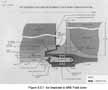
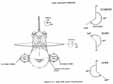
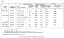
The STS 51-L lift-off loads were reconstructed and compared to design loads and flight measured loads for STS-1 through STS-7 (Figure 5.1.1). The Shuttle strut identification is shown in Figure 5.1.2. The element-to-element strut loads are used as good load indicators since all inter-element loads are carried throughout the struts. Strut loads were within design limit loads (loads before safety factor has been added) as were loads measured on the development flights.
Because the SRM field joints were the major concern, the reconstructed joint loads were compared to design loads. The major component of joint load is due to internal SRM pressure but external loads/dynamics also contribute. The SRM field joint loads were within the design load limit with the highest load occurring at the forward field joint, 15.2 x 10⁶ lbs axial equivalent. The mid joint load was 13.9 x 10⁶ lbs axial equivalent, while the aft joint showed - 13.8 x 10⁶ lbs axial equivalent load. All SRM joints were designed to - 17.2 x 10⁶ lbs equivalent axial limit load.
Loads were reconstructed for all in-flight events including roll maneuver and maximum dynamic pressure regime. As shown in Figure 5.1.3, the product of dynamic pressure and angle-of attack dropped outside the flight experience envelope around 55 seconds and again at 68 seconds. Also the variation in loads due to the vehicle response to wind shears and gusts was large but within design limits. The resulting loads, however, were well within design values since larger negative angles-of- attack reduce the overall aerodynamic loads on the wing and thus on the element-to-clement strut loads. The comparison of STS 51-L reconstructed loads with measured flight data of STS-1 thru STS-7, and to design limit loads, shows no violation of design allowable loads.
The SRM field joint loads are substantially lower for max Q than lift-off: - 11.6 x 10⁶ lbs axial equivalent for the forward field joint and -10. 6 x 10⁶ lbs axial equivalent for the aft field joint. The effect of the dynamic variations due to wind gusts is small due to the dominant role of pressure on SRM loads. These loads are well below the lift-off loads and the design limit loads.
5.2. Case Membrane Failure
Assessment of the potential for anomalies associated with the case membrane initiating the failure was conducted by analysis and review of design and test criteria. Potential failure modes were evaluated against the following criteria as dictated by flight data and photographic observations: (1) The bum through of the membrane would occur at or near the aft field joint, (2) the anomaly could have little or no influence on motor internal pressure since no deviation in pressure was observed prior to 60 seconds, (3) the anomaly would cause a burn through of the membrane in 58 seconds. The hypothesis of a membrane failure further requires that the initial smoke observed at 0.678 second was an independent event. This requirement coupled with the observations that the initial smoke was observed in the same vicinity as the eventual failure, makes a membrane failure an unlikely hypothesis for initiation of the accident.
Evaluation of potential insulation or inhibitor flaws against the three criteria above resulted in elimination of all candidates except a defect in the forward-facing inhibitor. The effects of a forward-facing inhibitor failure was evaluated by assuming a 1-inch-diameter hole at the base of the inhibitor. Analysis indicated that the change in motor internal pressure resulting from...
![[Top to bottom] Figure 5.1.1. AFT ET/SRB Liftoff Strut Loads; Figure 5.1.2. Shuttle Strut Identification; Figure 5.1.3. Trajectory Design Profile for STS 51-L.](https://www.nasa.gov/wp-content/uploads/static/history/rogersrep/v2l36s.jpg)
[L37]...this failure would probably not be detected. However, as extremely high erosion rate would be required (as compared to observed values) to produce a burn through of the membrane by 58 seconds. In addition, the assumed flaw is unlikely since the inhibitor is constructed by vulcanizing eight individual plies. Subsequent damage of the magnitude required is improbable and would be easily detected.
A review of fracture mechanics analysis and segment inspection and proof tests was conducted. After a proof test to a factor of 112 times maximum design operating pressure (which is designed to screen critical flaws), a magnetic particle inspection of the membrane was conducted. This inspection is capable of detecting flaws greater than 0.1 inches. Fracture mechanics analysis indicated that a flaw 0.1 inch long and 0.050 inch deep would grow to a flaw 0.122 inch long and 0.061 inch deep in 80 uses of the segment. This flaw would be less than a critical size. In addition, a failure resulting from a membrane flaw would manifest itself in a case rupture which is not consistent with observations.
Subsequent to these evaluations, two large fragments of the right SRM case containing the burn through area at the aft field joint were recovered. While evaluation of this hardware is still in progress, there is no evidence to substantiate a membrane failing, progressing slowly to the joint or that a membrane failure grew rapidly spanning the length of the SRM segment.
5.3. Propellant Anomalies
A design and flight data examination was accomplished to determine if any anomalous propellant conditions were present in the STS 51-L right SRM. Assessed were propellant cracking and propellant mean bulk temperatures.
Historically, the TP-H 1148 propellant family has exhibited good mechanical properties by an absence of grain structural problems. Should a crack occur, however, the effects would be evident in chamber pressure. The STS 51-L right SRM chamber pressure was 22 psi higher than that of the left SRB which would correlate to a 90° wedge crack. However, with a crack of this nature, the chamber pressure would have remained high for approximately 60 seconds. The right SRM chamber pressure did not remain high past 20-24 seconds and therefore the existence of a propellant crack was ruled out.
Propellant Mean Bulk Temperature (PMBT) calculations were made using the ambient temperature over the 2-week period prior to launch. The lowest PMBT experienced was 57°F on the day of launch which was 17°F above the minimum specified.
Based on this assessment and subscale, lot-acceptance, motor-firing evaluations, it is improbable that propellant anomalies contributed to the STS 51-L accident.
5.4. Joint/Seal Failure
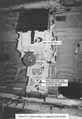
With the enhanced photographic and computer aided graphic data positioning, the flame from the right SRB near the aft field joint, and with the smoke at lift-off appearing at the same general location, the right SRB aft field joint/seal became the prime failure suspect. This supposition was confirmed when the Search, Recovery, and Reconstruction Team recovered an aft center segment portion and an aft segment portion of the joint containing a large burn through hole located at the suspected leak position (Figures 5.4.1 and 5.4.2). There have been several possible causes investigated that could have resulted in a joint leakage. These possible causes are treated in Section 6.0 of this report.
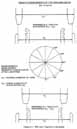
During stacking operations at the launch site, four segments are mated to form the SRM. The resulting joints are referred to as field joints, located and configured as depicted in Figure 6.0.1. Joint sealing is provided by two rubber O-rings (MILR-83248A) with diameters of 0.280" (+ 0.005", -0.003"),which are installed, as received from Morton Thiokol, during mating O-ring static compression after assembly is dictated by the gap between the tang and clevis (at the seals) which is governed by tang and clevis dimensions and the mating segments circumferences. The gap between the tang and clevis at any location after assembly is also influenced by the concentricity of the segments at mating. Zinc chromate putty is applied to the NBR insulation face prior to mating and in the mated configuration forms a barrier to prevent potential damage to the O-rings by combustion gas circumferential flow. The O-rings are designed to pressure actuate very early in the motor ignition transient. The gap between the tang and clevis increases as pressure loads are applied to the joint during ignition. The principal factor influencing the gap opening magnitude is motor pressure but gap opening is also influenced by external loads/dynamics.
The investigation has shown that the joint sealing performance is sensitive to the following factors, either independently or in combination:
The O-ring sealing performance sensitivity to these factors has been investigated using specific STS 51-L hardware dimensional configuration in extensive tests and analyses. The sensitivity to each factor was evaluated independently and in appropriate combinations to assess their potential to cause or contribute to the 51-L aft field joint failure.
It should be noted that most of the, testing was either laboratory or subscale tests. In many cases the data from these tests are considered to be directly applicable to the seal performance in full scale. However, in some cases there is a degree of uncertainty relative to scaling effects and complete simulation accuracy in extrapolating the data to full scale seal performance. Where such is the case, it is noted in the discussions of each seal performance factor that follows.
6.1. Assembly Damage/Contamination
Possible consequences of the mating operations which could influence joint sealing performance are damage to the O-rings or contamination generation. Prior to mating, the mating segments (tang and clevis) diameters are measured; Figure 6.1.1 depicts the measurements recorded at six locations, for both the mating tang and clevis. Due to case ovality resulting from shipping and handling, positive and negative diameter differences are frequently encountered. The interference between the tang and clevis at mating is directly proportional to the magnitude of these differences. With a positive difference, interference is encountered between the tang and the outer clevis leg at mating and with a negative difference, interference is encountered between the tang and the inner clevis leg (see Figure 6.1.1). Interference with the inner clevis leg is the condition that could result in assembly damage and/or generation of contaminants. There is a requirement that prohibits mating if the flat end of the tang contacts the flat upper end of the clevis. Mating procedures state that diametrical measurements at any of the six locations measured, should not exceed a positive 0. 250 inch difference. This controls "flat-on-flat" for a case where the diameter of the tang exceeds the clevis diameter. However, it does not control the potential for flat-on-flat, or any other interference conditions, between the tang and the inner clevis leg. A "flat-on-flat" condition can exist when the tang and clevis premate diametrical measurements have....
[L42] ....a negative difference in the range of -0.340 to -0.355 inches if the segment center lines are not co-aligned within approximately, 0.200 inches. This range covers clevis design dimensional tolerances. This condition existed for both right aft and center field joints with a somewhat higher probability on the aft field joint. It should also be noted that the burned hole in the recovered right SRM aft field joint tang segment coincided with the maximum measured negative diametrical difference of - 0.393 inches.
A review of prior anomalies provided some evidence that mating can result in damage to the joint/seal. Post-flight inspection reports indicated mechanical damage or pinch marks on a field joint O-ring from SRM 14A. Although not directly applicable to flight, in the ground test program one assembly incident occurred which damaged primary O-rings and one incident was encountered where shavings appeared in the sealing area after case disassembly. This experience lends credence to the postulation that damage can be sustained during mating and that contamination can be present in the joint.
Testing was conducted during the investigation to evaluate the potential for mating damage and contaminant generation along with its effect on seal performance. A section of a field joint was configured in a test fixture and simulated mating operations were conducted. Most significantly, metal slivers were generated under mating conditions in which the tang flat overlapped the flat end of the clevis lag by 0.005 to 0.010 inches. The metal slivers in turn were carried into the joint and deposited on and around the O-rings. A second significant finding from this test series was that the O-ring section increased in length as the tang entered the clevis and compressed the O-ring diameter. This length increase averaged 4.17%. The implication of this finding is that canted tang entry in a full diameter segment could "chase" the O-ring around the circumference, resulting in "gathering" (bulging from the groove) on the opposite side, thus making it more vulnerable to damage.
To understand the effects of potential contaminants on sealing performance, tests employing metal contaminants simulating those generated in the segment mating tests were conducted. The tests were structured to determine if the assembly induced metal shavings. positioned between the O-ring and sealing surface, could pass a static leak check but fail under dynamic conditions. Data show that all simulated metal contaminants tested produce essentially the same results within the variability of the data, and the thickness of contaminants which pass the 50 psig level check is in the 0.001 to 0.003 inch range. Testing is incomplete at this time to determine seal performance under dynamic conditions with this representative contamination, and therefore the possibility cannot be dismissed that contamination that could be generated by interference mating conditions could pass a leak check and yet cause the seal to leak under dynamic conditions.
A second concern for assembly damage is related to structural damage to the clevis due to abnormal loading. An analysis of the right SRM aft field joint mating conditions was performed to assess the induced loads relative to potential structural damage. The analysis was structured to determine the deflections and stresses experienced during mating of the right SRM aft center segment to the aft segment. These stresses were then used in a fracture mechanics analysis of the O-ring groove, The highest stressed area in the joint, to determine the flaw criticality; i.e.. the maximum flaw size that would not fail under the 51-L case segment life cycle history. Included in this analysis was the point load needed to deflect a suspended segment to the side by 0.200 inch and the maximum stress on the case cleaves this causes. The analysis further addressed a condition that has been encountered where the tang sits on top of the inner clevis leg on one side and slips down into the clevis groove on the diametrically opposite side.
The analysis results indicate that the stresses induced during the mating operation were low and would not have resulted in hardware damage. Also the stresses would not have resulted in significant growth of an undetected flaw substantially greater than that which is detectable by the inspection techniques employed.
6.2. Gap Opening
Tang/clevis sealing surface gap opening as a function of pressure and time was determined by a detailed finite element structural analysis which was calibrated to joint deflections measured on a pressurized structural test article without propellant. Analysis extended the results beyond test calibration conditions to include propellant effects and external loads. The combination of initial static gap dimensions with pressure driven gap opening time history determined the minimum and maximum gap response conditions used for testing the O-ring sealing capability.
The joint deflection analysis established tin, e histories for gap opening for primary and secondary O-rings for all field joints. These data indicate gap openings of approximately 0.029 inch and 0.017 inch for the primary and secondary O-rings respectively for the aft field joint. These values were used for subscale dynamic tests. Due to differences in motor pressure and loads, the gap opening for forward field joints is approximately 0.008 inch greater than for the aft field joints. Gap opening changes versus time are shown in Figure 6.2.1 for the aft field joints. The total gap at any time also depends on the initial static gap and on rounding effects during segment pressurization. Subscale tests were designed containing those variables as well as the changes in gap opening.
6.3. O-Ring Squeeze As Mated (Static)
As already noted, the static O-ring compression after mating is influenced by actual hardware dimensions and the degree of segment concentricity. Evaluation of these parameters for the right aft field joint for STS 51-L indicate that near metal-to-metal gaps may have existed at some locations. The difference in the true diameters of the mating surfaces measured at the factory was 0.008" which would have resulted in a minimum gap of less than 0. 004" at some location. Diameters measured just prior to mating indicated a significant ovality resulting in a lack of concentricity of the parts at mating. Across the 120° to 300°diameter (Figure 6.1.1), a 0.393" difference between the tang outer diameter and the clevis outer leg inner diameter existed at mating; i.e., tang diameter less than clevis diameter. This condition indicates that a maximum compression condition existed at the 300° location which is at the location where the joint leak occurred.
During the investigation, measurements were made on segments which had been refurbished and reused. The data indicate that segment circumferences at the sealing surfaces are changing with repeated use. This phenomenon is still under evaluation: however, applying the current limited data base to the right SRM aft field joint indicates that the potential for near metal-to-metal sealing surfaces was probably enhanced.
The maximum compression condition that existed for the right SRM aft field joint was not totally unique to this joint. Evaluation of the above factors indicated that this condition could also have existed on several other joints but to a somewhat lesser degree than for the right SRM aft field joint.
Analysis has shown and tests tend to confirm that the application of actuating pressure to the upstream face of the O-ring is essential to proper sealing performance. This occurs when there is a space between the upstream side of the O-ring groove and the upstream face of the O-ring. The existence of such a space is dependent upon the groove dimensions (width, depth, and sidewall angle), the O-ring diameter, the sealing gap and temperature.
Two subscale dynamic test fixtures were designed and built which simulated the initial static gap, gap opening rate and maximum gap opening, and motor ignition transient pressures. These fixtures were tested over a temperature range with varying initial static gap openings. A summary of results with initial gap openings of 0.020" and 0.004" is provided in Figure 6.3.1. The results indicate that with a 0.020 inch maximum initial gap,....
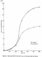
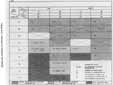
[L45] ....sealing can be achieved at temperatures below 25°F, while with 0.004 inch initial gap, scaling is not achieved at 25°F and becomes marginal in the 40°F and 50°F temperature range. For the .004 inch initial gap conditions, scaling without any gas blow-by past the O-rings occurred at 55°F. To evaluate the sensitivity to initial gap opening, four tests were conducted at 25°F with an initial gap of 0.010 inch. In contrast to the tests at 0.004 inch gap, these tests resulted in sealing but some minimal O-ring blow-by was observed during the sealing process. These tests show sensitivity to both temperature and O-ring squeeze. However, when the results are correlated with other test and analysis data, it is evident that the most significant factor in seal performance is the ability to get actuation pressure on the forward face of the O-ring. This is directly proportional to the hardware manufacturing tolerances and the degree of maximum squeeze condition. It should be noted that the test fixture used placed the O-rings at a specific initial gap and squeeze condition, uniformly around the circumference. It is not certain what, if any, circumferential pressure assist might occur from areas where maximum squeeze did not exist. Such effects could not be simulated in the subscale test results reported above.
6.4. Joint Temperature
Analyses were conducted to establish STS 51-L joint temperatures at launch. While some differences existed between the six 51-L field joints and while the joints on the right SRM had larger circumferential gradients than those on the left SRM at launch all joints had predicted local temperatures of 28 ± 50F Predicted transient temperatures for several circumferential locations on the joints are shown for the right SRM aft field joint and the left SRM aft field joint in Figures 6.4.1 and 6.4.2. These data are representative of other joints on the respective SRMs.
The investigation has shown that predicted launch temperatures had two effects that could potentially affect the seal performance: (1) O-ring resiliency degradation and (2) the potential for ice in the joints.
Consistent results from numerous O-ring resiliency tests have shown a resiliency degradation with reduced temperatures. Figure 6.4.3 provides O-ring recovery from 0.040 inches initial compression versus time from release of compression at temperatures ranging from 10°F to 75°F. When these data are compared with the gap openings versus time from Figure 6.2.1, it can be seen that the O-rings would not track nor recover to the gap opening at 600 milliseconds for temperatures significantly greater than those predicted for all field joints. These data show the importance of timely O-ring pressure actuation to achieve proper sealing.
It is probable that water intrusion occurred in some, if not all, STS 51-L field joints. Subsequent to the Challenger accident, it was learned that water had been observed in the STS-9 joints during destacking operations following exposure to less rain than that experienced by STS 51-L. It was reported that water had drained from the STS-9 joint when the pins were removed and that approximately 0.5 inches of water was present in the clevis bottom. While on the pad for 30 days, STS 51-L was exposed to approximately 7 inches of rain. Analyses and tests conducted to investigate this factor indicate that water in the joint will freeze under the environmental conditions experienced prior to the 51-L launch and could unseat the secondary O-ring. To determine the effects of unseating, tests were conducted on the sub-scale dynamic test fixture at Thiokol to further evaluate seal performance. For these tests, conditions relative to squeeze and gap opening were simulated which had demonstrated sealing capability without the presence of ice at 25°F. The primary O-ring was removed and water was frozen downstream of the secondary O-ring. With ice present. the O-ring failed to seal.
6.5. Putty Performance
Prior to the Challenger accident, the potential putty pressure scaling capability during motor pressurization had not been recognized in the joint design and evaluation- During the investigation, it became evident that several variables may affect the putty performance and in turn seal performance. Limited test data and lack of fidelity in full scale joint simulation prevented a complete engineering assessment of putty performance. Tests were conducted over a range of putty conditions including temperature at ignition, pretest conditioning to simulate the environmental effects and dimensional variables within the joint. These test results demonstrated that putty performance as a pressure seal is highly variable; and the results may be interpreted to indicate that the putty can maintain pressure during the ignition transient and prevent O-ring sealing over the range of variables tested. For example, one test conducted with putty which had been conditioned for 10 hours at 80% relative humidity and 75°F delayed the pressure rise at the primary O-ring for 530 milliseconds at a test temperature of 75°F. Tests at 20°F with similarly conditioned putty delayed the pressurization time by 1.9 seconds.
If the putty acts as a seal during the ignition transient and does not allow the motor pressure to seat the primary O-ring and then ruptures and allows motor pressure to the 6-rings after the tang/clevis gap has opened, the potential exists for the O-rings not to seal. Based on the previously discussed resiliency data and gap openings, a pressure delay of 500 milliseconds would result in a flow path greater than 0.010" between the O-rings and the tang sealing surface. These conditions combined with conditions previously discussed which prevent O-ring actuation pressure from acting on the upstream O-ring face severely restrict the seal capacity.
While these data indicate that the potential exists for O-rings not to seal, these data alone are not conclusive since the pressure, when released by the putty, provides a force tending to move the O-ring to its sealing surface. To evaluate this effect, a sub-scale test fixture was fabricated which effectively simulated gap opening at the time of putty rupture. These tests, simulating O-ring pressure actuation delay due to the putty holding motor pressure, were conducted over a range of temperatures, putty rupture time and initial O-ring squeeze. Test results, summarized in Figure 6.5.1, demonstrated that sealing performance is dependent on temperature and initial squeeze, both of which affect the pressure actuation capability of the O-rings. The tests indicate that sealing capability is marginal for maximum squeeze conditions, 0.004 inch initial gap, at 50°F with a pressure delay of 500 milliseconds. For the temperature and O-ring squeeze conditions which existed for several of the STS 51-L field joints. O-ring sealing was not achieved in these tests with simulated putty rupture times of 250 to 500 milliseconds.
1. A combustion gas leak through the right SRM aft field joint weakened and/or penetrated the ET hydrogen tank initiating vehicle structural breakup and loss of STS 51-L.
2. The evidence shows that no other STS 5-1 Shuttle elements or the payload contributed to the cause of the right SRM aft field joint combustion gas leak.
3. The right SRM aft field joint was observed leaking combustion gases within the first second after ignition. The leak became clearly evident at approximately 58 seconds into the flight. It is possible that the leak was continuous but unobservable or non-existent in portions of the intervening period. In either case, it is possible that vehicle response to wind gust and planned maneuvers contributed to the leakage growth at the degraded joint location.
4. The location of the right SRB aft field joint combustion gas leak coincided with the approximate location of maximum interference between the joint tang and inner clevis leg at assembly. This mating interference can exist using approved assembly procedures, which for STS 51-L, were implemented properly.
a. Mating conditions at this location could result in maximum squeeze (minimum initial gap) on the O-rings.
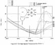
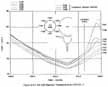
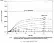
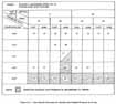
[L49] b. Mating conditions at this location afforded the highest potential for undetected joint damage and/or contaminant generation which could degrade seal performance.
5. The SRM joint has design deficiencies and may not seal properly with combined variable conditions existing on the STS 51-L flight and probably led to the failure. Tests conducted during this investigation indicated that:
a. The joint sealing performance is significantly degraded as joint rotation increases the gap when O-rings are subjected to temperatures below 40-50°F and maximum squeeze conditions in the range of .004 inches. The STS 51-L SRM joint/ O-ring temperature was approximately 28°F and maximum squeeze was probable. Maximum squeeze is a significant factor because it compresses the O-ring against its groove walls prohibiting pressure actuation. This squeeze condition is aggravated by the design leak test feature that places the primary O-ring in an unfavorable position making it more difficult to pressure actuate the 0-ring to its proper sealing position.
b. Putty performance in the joint seal may not be as intended by the design. Specifically, these tests indicate that putty variables, such as humidity, can delay timely actuation pressure to the O-rings. In addition, testing and STS 61-G destacking observations indicate that several blow-hole gas paths per joint can exist at motor ignition that can concentrate hot gas flow and cause the O-rings to erode. Under these conditions and in combination with other factors, joint seal performance would be significantly degraded.
c. Ice in the joint can inhibit proper secondary seal performance. There is a distinct possibility that water intrusion into the STS 51-L joint occurred since investigative activities revealed water in the STS-9 joints during a destack operation after exposure to less rainfall than STS 51-L. Conditions were such that water present in the joint would result in ice at time of launch.
6. The joint that failed was not found to be unique in that many of the factors identified and assessed during the investigation that can adversely effect seal performance were present to varying degrees in other SRM field joints on STS 51-L. It is therefore necessary to modify the SRM joint design to preclude or eliminate the effect of all these factors and/or conditions acting singularly and in combinations.
General Assignment for Accident Analysis Team
The Accident Analysis Team shall perform, as a priority task, the Task Force efforts needed to respond to the needs and interests of the Accident Analysis Panel of the Presidential Commission. The Team Lead and his deputy shall establish a working relationship with the Commission Panel Leader consistent with the procedures of the Task Force and the Commission.
The Accident Analysis Team shall develop the possible causes of the 51-L accident. The team shall review and analyze all anomalous aspects of the STS 51-L preparation, launch, and flight and relate those anomalies to the accident to the extent possible. The team shall develop comprehensive failure scenarios that postulates both the causes and sequence of events relating to the accident. The team shall consider all elements of the STS and shall develop and maintain a data base as follows as it relates to failure analysis activities:
- 1. Launch configuration
- 2. Prelaunch, launch. and flight environment
- 3. Flight data and post flight data
- 4. Anomaly List
- 5. Integrated sequence of events
- 6. Element and system performance and constraints
The Team shall assist the Commission in its investigation in these areas of anomaly identification and classification as well as scenario development. Further, the Team shall assist the Commission in all matters related to the Commission having an adequate mishap data base so that the Commission can conclude its work in a timely fashion.