[54] Presidential Commission
Recommendation VI
Landing Safety. NASA must take actions to improve landing safety.
[55] Prior to the accident, component and systems testing, simulations, and flight analysis results had identified a need to improve the landing system. The improvements included a requirement to increase brake capacity, eliminate mechanical and thermally induced brake damage, improve steering margin, and reduce the effects of tire damage or failure. Subsequent analysis, test, and a series of simulations conducted at the Ames Research Center vertical motion simulator in April 1987 addressed overall landing safety.
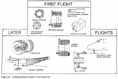
As a result of this analysis and test activity, several design improvements (Figure 25)....
[56] .....have been instituted to improve the margins of safety for the landing/deceleration system. Some of these improvements are modifications to existing designs and will be completed prior to the next flight. Other improvements involve the development of new designs to improve performance margins and the reliability of the overall system and, if certified and approved for flight, will be incorporated later in the program.
BRAKING SYSTEM IMPROVEMENTS
Two major brake improvement programs are currently under way: an interim brake system upgrade and a longer-term carbon brake development program. The interim program provides for an increased brake energy absorption capability, modification of the brake anti-skid system, modified brake wear-in procedures, installation of flow restrictors in the brake hydraulic piston housing, and a stiffened main gear axle.
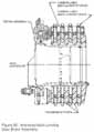
The energy absorption capability of the brakes is a concern. Localized hot spots in the brake cause reduced stator strength in the structural load reaction path and result in stator failure. Additional material is being added to two of the three beryllium stators (Figure 26) to increase heat sink capability and reduce the temperature rise rate. This change will increase stator load reaction ability and minimize resultant wear.
Brake/anti-skid system tolerance buildups have resulted in unequal brake pressure application to adjacent brakes on the same landing gear strut. This pressure differential prevents full utilization of the brake capacity. Modification of the brake anti-skid system to provide an electrical adjustment method will ensure that the brake pressure is equalized or balanced. A second design modification will remove the anti-skid system sensory circuit that reduces the brake pressure to the opposite wheel if a flat tire is detected.
The thicker stators and the modified anti-skid system are expected to provide an overall brake system capacity of 65 million foot-pounds-an approximate 18-percent increase in energy absorption capacity over the present capability. Mission planning and...
....landing performance analyses will continue to utilize a nominal energy capacity of 55 million foot-pounds, thus providing an additional margin of safety for landing.
The brakes will be exposed to wear-in runs with higher energy and pressure during acceptance tests at the supplier. This technique was used successfully for several flight brake sets prior to STS 51-L, with no indication of dynamically induced brake damage during subsequent landings.
Analysis of flight data collected on the STS 41-G mission indicated the need to restrict the free flow of hydraulic fluid within the brake piston housing to eliminate the potential for a "whirl" phenomenon that can cause major dynamic loads to be imposed on the brake. Six orifices (flow reduction devices) are being added to the brake hydraulic piston housing to provide the flow reduction and to reduce the dynamic loads and the resultant damage to the brakes.
Stiffer landing gear axles are being installed to reduce wheel/brake relative [57] deflection and minimize the unequal brake loading and tire shoulder wear.
Each of these modifications to the landing system hardware is currently in work. The modified hardware will be analyzed, tested, and certified before being installed for the next flight. Engineering data obtained from instrumentation being added to the first flight vehicle will be used to analyze the overall brake system performance and to verify that these changes provide the desired safety margins.
A tire pressure monitoring system, similar to that used during prelaunch on flights STS-l through STS-5, is being installed on all vehicles. This instrumentation provides redundant strain gages on the nose and main wheels to indicate tire pressure. The tire pressure data will now be available for in-flight monitoring by the flight crew and Mission Control Center. Knowledge of tire pressure prior to landing will enhance overall landing safety. If it is determined that a tire(s) has insufficient pressure to support the landing loads, steps can be taken to land on the safest runway for the particular situation.
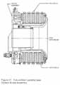
Development of a structural carbon brake (Figure 27) is under way. The "structural" carbon brake utilizes the carbon material of each rotor and stator as the load-reacting member. The design incorporates an additional rotor and stator and will provide an energy absorption capability of 85 million foot-pounds, which represents an approximate 55-percent increase over the present design. Overall capability and performance margin of this brake will be demonstrated by ground testing to 100 million foot-pounds. Key milestones include a critical design review in July 1987 and the beginning of qualification testing in February 1988.
NOSE WHEEL STEERING
Nose wheel steering is used for directional control (steering) of the orbiter during a crosswind landing and roll-out or in the event of a blown tire (or tires). The current system has the capability to provide the required steering but lacks complete redundancy. Studies are under way to determine those features that could be incorporated....
....into the system design to maximize redundancy. The current system is fail-safe in that several single failures can cause it to default to a free caster mode (no positive directional control), necessitating the use of differential braking to steer during roll-out. Design options being considered would enhance the system fault tolerance to a fail-operational/ fail-safe condition.
TIRE IMPROVEMENTS
A tire improvement/runway surface study is now in progress to determine how to decrease the tire wear experienced during KSC landings, while maintaining an acceptable traction level in the event of landing on a wet runway. Because of the abrasive surface of the KSC runway, significant tire wear has been experienced at touchdown and during crosswind landings and roll-out.
Analyses are being performed to determine what changes can be made to the KSC runway surface to reduce tire wear, while maintaining a limited wet runway capability. These analyses include potential techniques [58] for smoothing the surface, such as grinding, sandblasting, or painting. The program is committed to better understanding the contribution of the surface to tire damage and to determining the options for modifying the surface prior to resumption of planned end-of-mission landings at KSC.
Extensive tire tests have been conducted at the Aircraft Landing Dynamics Facility at the NASA Langley Research Center to obtain a data base for better understanding the orbiter tire wear and performance characteristics. This facility provides the capability to duplicate orbiter touchdown velocity, to simulate vehicle yaw angles experienced during a crosswind landing, and to simulate the tire loading during the landing roll-out. This capability, combined with the ability to change the runway surface finish, provides a base from which parametric tire-to-surface performance characteristics can be generated. The worn tires are then tested on a dynamometer at the Wright Patterson Air Force Base to determine the remaining useful life.
Modified tires were tested at the Langley facility. The modifications consisted of added tread rubber thickness and a change in the tread rubber compound to increase the wear-resistant properties of the tire. Test results were favorable, and analysis is continuing; however, any change to the tire would require complete verification and would not support the early flights.
OTHER STUDIES
An end-of-runway barrier and a drag chute are being assessed to determine their potential contributions to increasing landing margin and safety. Other studies are evaluating changes to orbiter landing procedures to minimize tire wear and landing gear support for a failed tire.
Orbiter Arresting System
An orbiter arresting system (runway barrier) is being developed. This system, which would be deployed approximately 600 feet from the roll-out end of the runway, is designed to safely stop a 260,000-pound orbiter traveling at 100 knots or less, without injury to the crew. A preliminary design review is scheduled for June 1987 and first installation is planned for no earlier than February 1988. No decision has been made on which runways would incorporate such a capability.
Drag Chute
An orbiter drag chute deceleration system study was initiated in October 1986. The study is determining the best location, method of attachment, size, and weight of a drag chute necessary to stop the orbiter within 7,500 feet after main gear touchdown.
Testing performed at the vertical motion simulator determined that use of a drag chute, deployed at touchdown, can reduce roll-out distance, improve handling qualities, and reduce tire loads and required brake energies. Orbiter installation design options for the drag chute are being assessed; however, no decision to install the system has been made.
Landing Gear Strut/Roll on Rim Capability
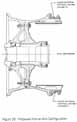
Other studies are under way to determine potential improvements for landing safety. These include analysis of gear skids attached to the landing gear struts to provide a protective wear surface if a tire fails (Figure 28); a strengthened wheel rim to provide a roll-on-rim capability in the event of tire(s) failure (Figure 29); and a main gear wheel spin-up technique to reduce the depth of the tire....
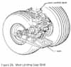
[59]....tread wear that occurs at touchdown. No decision to incorporate any of these potential improvements has been made.
Landing Gear Load Reduction
Methods for reducing the main gear rollout loads, to minimize the potential for blown tires, are being assessed. Loads are generated by negative lift (aerodynamic down force on wings and fuselage) induced by the orbiter's nose-down rolling attitude. A computer software modification has been approved that will position the elevons automatically to a down position after nose wheel touchdown. This will reduce the load on the main tires and will improve the safety margins on the landing gear assembly.
LANDING CRITERIA
Integrated landing system testing will be performed to satisfy detailed test objectives during early flights scheduled to land at Edwards Air Force Base (EAFB). The results of laboratory and simulator testing and orbiter landings will be used to develop and refine the appropriate flight mission rules and crew procedures associated with landing. Total understanding of all performance data, successful resolution of all significant anomalies, and confidence in the enhanced weather prediction capability will be constraints to resuming planned end-of-mission (EOM) landings at KSC.
WEATHER
The Space Shuttle Weather Forecasting Advisory Panel, chaired by Dr. John Theon, was established by NASA Headquarters to review existing weather support capabilities and plans and to recommend a course of action to the NSTS Program. Included on the panel were representatives from NASA, the National Oceanic and Atmospheric Administration (NOAA), the Air Force, and the National Center for Atmospheric Research.
The panel examined skills, equipment, and techniques available to the Space Shuttle weather support staff. Panel recom....
....mendations included improvements to forecasting procedures, personnel policies, and data communications as well as technological improvements. Key proposed equipment changes included airborne sensors, to quantify precipitation in the Cape Kennedy area, and better wind forecasting equipment. NSTS representatives will continue to work with the advisory panel and with NOAA to ensure that the best forecasting equipment and procedures are available to the program.
NASA has revalidated the statistical weather data base for all Space Shuttle landing sites and has established minimum weather measuring equipment requirements for EOM and abort sites. Equipment requirements not currently in place are being reviewed for future implementation.
For the transatlantic abort landing sites, the approved changes include the addition of both a ground-based and an airborne weather observer, availability of European weather satellite data at the Johnson Space [60] Center, and augmentation of on-site weather monitoring equipment such as remote sensing stations and balloon release and tracking equipment. The capabilities of continental United States landing sites are being assessed to ensure that weather decisions are made with accurate and timely data.
NASA has requested assistance from the National Academy of Sciences to identify concepts for equipping the Kennedy Space Center with the necessary instrumentation to provide a prototype forecasting facility capable of a 90-minute, high-confidence-level forecast.
A second objective being discussed with the National Research Council is a program that would encourage the research community to sponsor atmospheric activities, utilizing KSC as a test location, for the application of state-of-the-science meteorological forecasting techniques and technology. The council has appointed its Mesoscale Research Panel to address this request and to provide NASA with an implementation plan.
DUAL FERRY CAPABILITY
NASA has assessed the requirements and initiated budgetary actions for an additional Boeing 747 aircraft to provide an NSTS dual ferry capability. Funding for the aircraft modification kit used to attach the orbiter to the aircraft has been approved, and funding for an additional aircraft has been requested. With the availability of the second aircraft, the dual ferry capability will be operational by 1990.