|
SUBMITTED BY: |
|
|
|
|
|
APPROVED BY: |
|
|
|
|
|
|
|
|
|
|
[L52] I. Organization/Responsibilities
The organization and responsibilities of the SRM Working Group were in accordance with the Shuttle Contingency Plan. The following is a listing of the SRM Group along with the area of responsibility for each member. A listing of other key participants, both NASA and contractor, is also given.
|
R. J. SCHWINGHAMER |
EHOI |
CHAIRMAN |
|
J. C. BLAIR |
EDO1 |
CO-CHAIRMAN, TIMELINE AND ACTION ITEMS |
|
D. R. BOUSSOM |
CS21 |
SAFETY |
|
G. T. JAMISON |
EP42 |
STRESS |
|
J. Q. MILLER |
SA42 |
MTI ANALYSIS |
|
W. A. RIEHL |
EH31 |
MATERIALS AND TEST |
|
M. CARR |
EGII |
QUALITY AND RELIABILITY |
|
R. C. MIZE |
EH44 |
SECRETARY |
|
C. R. McINTOSH |
EEl1 |
RECOVERY |
Key Morton Thiokol, Inc., personnel participating throughout the investigatory period in the Huntsville Operations Support Center are as follows:
|
KILMINSTER, J. |
GROUP LEADER |
|
BRINTON, B. |
ALTERNATE GROUP LEADER |
|
ADAMS, I. |
|
|
BUNKER, R. |
|
|
MACBETH, A. |
|
|
POTTER.D. |
|
|
THOMPSON, A. |
|
|
THOMPSON, B. |
|
|
|
|
|
|
|
|
ANDERSON, J. |
ED44 |
McCARTY, J, |
EPO1 | |
|
AUSTIN. J. |
EH32 |
McCAY, D. |
EP21 | |
|
BACCHUS, D. |
ED32 |
McCLUNEY, S. |
ET35 | |
|
BACTHEL, G. |
EP44 |
McKANNAN, E. |
EHO1 | |
|
BIANCA, C. |
EP42 |
MILL ER, C. |
EP36 | |
|
BOYD, G. |
EG24 |
MITCHELL, L. |
EH44 | |
|
BRAMON, C. |
EH44 |
MONTANA, J. |
EH22 | |
|
BROLLIAR, R |
EP42 |
MOORE, C. |
ED22 | |
|
CARUSO, S. |
EH32 |
MOORE, D. |
EH23 | |
|
CLANTON, J. |
EG22 |
MOORE, J. |
EP42 | |
|
CLEMONS, J. |
EH33 |
MOORE, M. |
EP36 | |
|
CLINTON, R. |
EH34 |
MUNAFO, P. |
EH22 | |
|
COLBERG, W. |
EH43 |
NIBLETT, J. |
EP25 | |
|
COSTES. N. |
ED42 |
NICHOLS, R. |
EH34 | |
|
COUNTS, R. |
EP23 |
PATTERSON, J. |
EH33 | |
|
CRAIG, L. |
EP42 |
PARKER, J. |
ED23 | |
|
CRAMER, J. |
EP24 |
PARR, R. |
EH22 | |
|
DAHM, W. |
EP31 |
POWERS, L. |
EP25 | |
|
DECASTRA, J. |
EG12 |
QUONG, H, |
NASA/HDQRS | |
|
DOLAN, F. |
EH14 |
RANSBURGH, J. |
ET35 | |
|
EHL, J. |
EH44 |
RAY, L. |
EP25 | |
|
ELKINS, B. |
EP15 |
RODRIGUEZ, P. |
EP15 | |
|
FICHTL. G. |
ED42 |
RYAN, R. |
ED21 | |
|
FISHER, R. |
EP44 |
SANDRIDGE, D. |
ET35 | |
|
FOSTER, L. |
ED33 |
SCHUERER, P. |
EH41 | |
|
FREDERICK, P. |
EP41 |
SHACKLEFORD, B. |
EP25 | |
|
GAUSE. R. |
EH11 |
SNODDY,D. |
ET52 | |
|
GREENWOOD, T, |
ED33 |
STALLWORTH, R. |
EP42 | |
|
HERDA, D. |
EP42 |
STINSON, T. |
EP46 | |
|
HESTER, J. |
EP25 |
SWANSON, G. |
EP42 | |
|
HILL, W, |
EH43 |
TAYLOR, R. |
EH11 | |
|
HUTT. J. |
EP26 |
TEPOOL, R. |
ET65 | |
|
JONES, J. |
EP22 |
THOMPSON, L. |
EH33 | |
|
JONES. K. |
EE11 |
TOWNSEND, J. |
ED22 | |
|
KELLER,V. |
EP42 |
TURNER, J. |
EH33 | |
|
KELLEY, T. |
EP36 |
WEBB, D. |
EH34 | |
|
[L53] KIEFLING, L. |
ED22 |
WEGRICH, R. |
EH32 | |
|
LEE. H. |
EP42 |
WHITAKER, A. |
EH11 | |
|
LYLES, G. |
EP26 |
WILLIAMS, J. |
ET31 | |
|
MADOLE, P. |
EG01 |
WOOD, D. |
EH44 | |
|
MANN, W. |
EE11 |
VORLUND, A. |
EP21 | |
|
|
|
YOUNG, G. |
EP23 |
|
AYCOCK, VV. |
(MTI) |
McCREARY, W. |
(MTI) |
|
BAKES, R. |
(MTI) |
McDONALD, A. |
(MTI) |
|
BOISJOLY, R. |
(MTI) |
McGRATH, M. |
(USBI) |
|
BOWMAN, R. |
(MTI) |
McVEY, L. |
(MTI) |
|
BRASFIELD. F. |
(MTI) |
MILLER, L. |
(MTI) |
|
COX. M. |
(MTI) |
MORSTADT, R. |
(MTI) |
|
DAVIDSON, T. |
(MTI) |
NEALE, J. |
(MTI) |
|
FOLEY, M. |
(MTI) |
NIELSON, A. |
(MTI) |
|
FULMER, D. |
(LOCKHEED) |
SPEAS, K. |
(MTI) |
|
GARRISON, E. |
(MTI) |
SHADLASKY, P. |
(MTI) |
|
HARPER, E. |
(MTI) |
THER, N. |
(MTI) |
|
KETNER, D. |
(MTI) |
THIRKILL, J. |
(MTI) |
|
LINDSTROM, R. |
(MTI) |
WIGGINS, C. |
(MTI) |
|
MASON, J. |
(MTI) |
|
|
The SRM Working Group was activated in accordance with the Space Shuttle Contingency Plan, MSFC-SSCP-5-77, Rev. Q, July 8, 1985, immediately following the Challenger incident. Following the establishment of the NASA Task Force, the SRM Working Group activities were directed in support of the Accident Analysis Team of the Data and Design Analysis Task Force.
The investigation activities of the group were conducted in general accordance with MMI 1711.2d, Mishap Reporting and Investigation, April 16, 1984.
Build Records and Discrepancy Report Reviews
Build records and discrepancy report reviews were initiated early in the investigation. The object was to determine whether errors or omissions in the planning and discrepancy reporting documents existed and if so, to determine whether they could have contributed to the anomaly. The build records and discrepancy documents were obtained from MTI, Wasatch, and KSC and were reviewed by Senior personnel in Materials and Processes and Reliability and Quality Assurance. Discrepancies requiring special analysis to disposition were further reviewed by specialists in stress, O-ring application, flex bearing engineering, and metallurgy.
Build records and discrepancy documents assessed by the SRM Accident Investigation Document Review Team included: all discrepancy documents written against parts and materials used in the 51-L right booster, all shop travelers, all KSC stacking documents, and all KSC problem reports.
All discrepancy reports, process departures, and parts rejection reports reported against the 51-L right motor components by Morton Thiokol were reviewed. The majority of discrepancies can be categorized as minor in nature and many are associated with reuse of the hardware. The disposition given all the discrepancies, except one, were upheld by the Review Team.
The single exception, DR 110487-04, was considered improperly dispositioned in that pitting on the nozzle throat housing sealing surface was accepted for "Use As Is" without rework. Sealing surfaces typically are considered critical to part functioning and should not be compromised. But after careful analysis it was concluded that this discrepancy did not have any influence on the 51-L incident. Photographic evidence shows the nozzle throat housing was not involved.
Two Problem Reports (PRs) were issued at KSC against the 51-L, right motor, aft center segment to aft segment field joint. These were minor in nature and considered properly dispositioned.
A total of 287 Common Planning Indices (CPIs) used to construct the 51-L right motor were reviewed by the Group. The CPIs were reviewed for clarity of instructions and for completeness of buyoff; i.e., all steps and logs were properly stamped and approved by MTI manufacturing, engineering, and Quality and Air Force Quality.
The CPIs were determined to be well written with extensive detail including numerous inspection and verification points.
All CPIs were properly dispositioned. All manufacturing quality and Air Force mandatory verifications were properly accomplished. The CPIs were mature planning documents; some had been used more than 100 times to fabricate major components for qualification, test and flight. The majority had been used between 14 and 60 times.
It was determined that there had been no Class 1 changes to the planning system or individual documents between the previous use and 51-L. It was further determined that there was no limited use hardware employed in any field joint for the right SBM. Some limited use restrictions were in place but they were confined to factory joints and were well documented.
Finally, the extensive review of SRM build records did not reveal any irregularities that could have contributed to failure of the 51-L right Solid Rocket Motor.
[L54] Possible SRM Failure Modes
Failure modes were identified and each assessed against the failure investigation data base. This data base consisted of Mission 51-L photographic, telemetry, prelaunch, design, and manufacturing data. This database was progressively expanded during the course of the investigation through a review of previous flight and test data and with tests and analyses performed in direct support of the investigation.
During the investigation the potential failure modes listed below were identified and evaluated:
A. SRM Hot Gas Leak
- 1. Internal Heating/Inhibitor/Insulation Anomalies
- 2. LH2 leak impingement on SRM
- 3. Assembly Conditions/Anomalies
- 4. Primary O-ring blow-by or low temperature effects coupled with either:
- secondary O-ring defect or
- ice in joint or
- leak check port leaks or
- O-ring actuation time delayed by lower temperature
- 5. Load exceedance effects
- 6. Putty delaying pressure to primary O-ring
- 7. Case rupture
Other Possible Modes
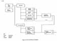
Much of the initial photographic data review resulted in focusing on investigation of failure modes that could result in a hot gas leak from the right SRM. The primary emphasis of the investigation was placed on failure modes A.1 thru A.7. Subsequent hardware recovery has confirmed this to be the proper focus for the failure investigation. Failure modes B thru P were discounted early based on empirical data and analyses. Supporting rationale for conclusions of all the failure modes will be presented in Section IV of this report.
A failure scenario diagram (Figure 1) was devised to assist in a systematic evaluation of each hot gas leak failure scenario mechanism. Each scenario will be treated in subsequent sections of this report, except Scenarios A.2 and A.5. Scenario A.2 is covered in the External Tank Final Report and Scenario A.5 is covered in the Systems Final Report.
III. Definition of Terms and Acronyms
|
APU |
AUXILIARY POWER UNIT |
|
BET |
BEST ESTIMATED TRAJECTORY |
|
BSM |
BOOSTER SEPARATION MOTOR |
|
BTU |
BRITISH THERMAL UNIT |
|
CDF |
CONFINED DETONATING FUSE |
|
CDR |
CRITICAL DESIGN REVIEW |
|
CEI |
CONTRACT END ITEM |
|
C/O |
CHECKOUT |
|
CPI |
COMMON PLANNING INDICES |
|
CTPB |
CARBOXYL TERMINATED POLYBUTADIENE |
|
DD |
DEEP DRONE (UNMANNED SUBMARINE) |
|
DFI |
DEVELOPMENT FLIGHT INSTRUMENTATION |
|
DM |
DEVELOPMENT MOTOR |
|
DR |
DISCREPANCY REPORT |
|
E&I |
ELECTRICAL AND INSTRUMENTATION |
|
EPDM |
ETHYLENE PROPYLENE TER POLYMER |
|
ESD |
ELECTROSTATIC DISCHARGE |
|
ET |
EXTERNAL TANK |
|
ETA |
EXTERNAL TANK ATTACH |
|
ETR |
EASTERN TEST RANGE |
|
EWAT |
END WEB ACTION TIME |
|
EWT |
END WEB TIME |
|
FLT |
FLIGHT |
|
FSM |
FUEL SUPPLY MODULE |
|
FSS |
FIXED SERVICE STRUCTURE |
|
FTU |
ULTIMATE TENSILE STRESS |
|
FTY |
YIELD TENSILE STRESS |
|
FWD |
FORWARD |
|
GSE |
GROUND SUPPORT EQUIPMENT |
|
HMX |
CYCLOTETRAMETHYLENE TETRA |
|
HNS |
NITRAMINE |
|
HP |
HEXA NITRO STILBENE |
|
HPM |
HIGH PRESSURE |
|
HPU |
HIGH PERFORMANCE MOTOR |
|
IMU |
HYDRAULIC POWER UNIT |
|
Lus |
INERTIAL MEASUREMENT UNIT INERTIAL UPPER STAGE |
|
JSL |
JOHNSON SEA LINK (FOUR-MAN SUBMARINE) |
|
KSI |
THOUSANDS OF POUNDS PER INCH |
|
LANL |
LOS ALAMOS NATIONAL LABORATORY |
|
LBM |
POUNDS MASS |
|
LG |
LARGE |
|
LH |
LEFT HAND |
|
LSC |
LINEAR SHAPED CHARGE |
|
LT |
LIGHT |
|
LVDT |
LINEAR VARIABLE DIFFERENTIAL TRANSFORMER |
|
MAX Q |
MAXIMUM DYNAMIC PRESSURE |
|
MEOP |
MAXIMUM EXPECTED OPERATING PRESSURE |
|
MET |
MISSION ELAPSED TIME |
|
MiLS |
THOUSANDTHS OF AN INCH |
|
MIN |
MINIMUM |
|
MOF |
MANNED ORBITAL FLIGHT |
|
MLP |
MOBILE LAUNCH PLATFORM |
|
MMI |
MARSHALL MANAGEMENT INSTRUCTION |
|
M&P |
MATERIALS AND PROCESSING |
|
MTI |
MORTON THIOKOL, INCORPORATED |
|
NBR |
NITRILE BUTADIENE RUBBER |
|
NDI |
NONDESTRUCTIVE INSPECTION |
|
NDT |
NONDESTRUCTIVE TESTING |
|
NPIC |
NATIONAL PHOTOGRAPHIC INTERPRETATION CENTER |
|
NRA |
NUCLEAR RESEARCH SUBMARINE |
|
NSI |
NASA STANDARD INITIATOR |
|
NSTL |
NATIONAL SPACE TECHNOLOGY LABORATORY |
|
OF |
OPERATIONAL FLIGHT |
|
OFI |
OPERATIONAL FLIGHT INSTRUMENTATION' |
|
OPT |
OPERATIONAL FLIGHT TRANSDUCERS |
|
ORB |
ORBITER |
|
OV |
ORBITER VEHICLE |
|
[L56] PBAN |
POLYBUTADIENE ACRYLONITRILE (PROPELLANT) |
|
PETN |
PENTA ERYTHRITE TETRA NITRATE |
|
PDR |
PRELIMINARY DESIGN REVIEW |
|
PIC |
PYROTECHNIC INITIATOR CONTROLLER |
|
PR |
PROBLEM REPORT |
|
PRI |
PRIMARY |
|
PSI |
POUNDS PER SQUARE INCH |
|
PSIA |
POUNDS PER SQUARE INCH -ABSOLUTE |
|
PSID |
POUNDS PER SQUARE INCH-DIFFERENTIAL |
|
PSIG |
POUNDS PER SQUARE INCH GAGE |
|
Q |
DYNAMIC PRESSURE (POUNDS PER SQUARE FOOT) |
|
Q MAX |
MAXIMUM DYNAMIC PRESSURE DURING ASCENT |
|
RDX |
CYCLO TRIMETHYLENE TRINITRAMINE |
|
RH |
RIGHT HAND, or RELATIVE HUMIDITY |
|
RPC |
REMOTE POWER CONTROLLER |
|
R&QA |
RELIABILITY AND QUALITY ASSURANCE |
|
RSS |
RANGE SAFETY SYSTEM or ROOT SUM SQUARED |
|
S&A |
SAFE AND ARM DEVICE |
|
SBPE |
SPACE BOOSTER PROJECT ENGINEERING |
|
SEG |
SEGMENT |
|
SRB |
SOLID ROCKET BOOSTER |
|
SRM |
SOLID ROCKET MOTOR |
|
SRMPO |
SOLID ROCKET MOTOR PROJECT OFFICE |
|
SSME |
SPACE SHUTTLE MAIN ENGINE |
|
STA |
STATION |
|
STS |
SPACE TRANSPORTATION SYSTEM |
|
TBD |
TO BE DETERMINED |
|
T/C |
THERMOCOUPLE |
|
TDRS |
TRACKING AND DATA RELAY SATELLITE |
|
TPS |
THERMAL PROTECTION SYSTEM |
|
TVC |
THRUST VECTOR CONTROL |
|
USBI |
UNITED SPACE BOOSTER, INCORPORATED |
|
VAB |
VERTICAL ASSEMBLY BUILDING |
|
VAFB |
VANDENBERG AIR FORCE BASE |
|
WTR |
WESTERN TEST RANGE |
SRM Description
The total SRB element of the Space Shuttle is composed of six subsystems: The Solid Rocket Motor (SRM), the structural subsystem, the Thrust Vector Control (TVC) subsystem, the mechanical and ordnance equipment subsystem, the recovery subsystem containing the mechanical and parachute equipment, and the electrical subsystem including the Range Safety System (RSS). All elements except the nose cap and separation motors are intended to be reusable and are recovered via drogue and main parachutes.
The SRM is the primary propulsive element providing impulse and TVC from ignition to SRB staging. The SRM consists essentially of lined, insulated, segmented, weldless D6AC steel rocket motor cases loaded with TP-H1148 propellant. TP-H1148 is a composite type solid propellant formulated of polybutadiene acrylonitrile (PBAN), terpolymer binder, ammonium perchlorate, and aluminum powder, with a small amount of iron oxide burning rate catalyst. An ignition system, initiators, igniter, movable nozzle, systems tunnel, and instrumentation are other essential parts of the SRM.
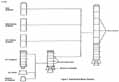
Performance interchangeability and replaceability between a flight set of SRBs are maintained by matching the burning rates of motor segments cast in matched pairs from the same propellant lot. The sea level thrust of the SRM is 2.65 million pounds. The propellant grain design is performance tailored, consisting of a forward segment with an 11-point star and transitioning into a cylindrical perforated configuration in the cylindrical portion of the segment, two identically configured center segments that are tapered cylindrical perforated and an aft segment with a dual taper cylindrical perforated configuration. Figure 2 shows how the SRM is segmented indicating the field joints.
The 11-point star configuration in the forward SRM segment produces high level lift-off thrust until burnout of the star. Burning of the cylindrical perforated configuration continues until thrust decay due to burnout. A linear, 10-second thrust decay is achieved by the programmed burnout of slivers in all segments.
The insulation used in the chamber, propellant relief flaps, and forward inhibitors is asbestos- silica-filled nitrile butadiene rubber (NBR). The aft inhibitor insulation material is an asbestos filled carboxyl terminated polybutadiene (CTPB) polymer. The inhibitors typically are designed to prevent ignition and burning of the propellant grain in a direction perpendicular to the inhibitor surface. The case liner material is an asbestos-filled CTPB polymer (UF-2137).
The SRM nozzle is a convergent divergent movable design containing an aft pivot point, flexible bearing as the gimbal mechanism. This type of bearing has been used previously in the Poseidon missile; however, the SRM nozzle and flexible bearing are larger than any others in current use.
STS 51-L Incident Timeline Summary
The STS 51-L Mission Space Shuttle, Challenger, received the SRM ignition command at 11:38:01 a.m. EST on January 28, 1986, at the Kennedy Space Center. At 0.678 seconds, mission elapsed time (MET), an anomalous cloud of smoke appeared (according to camera E60 film) in the 270° to 0° quadrant of the right SRM at (or near) the aft field joint. This smoke persisted at least until 3.35 seconds MET. Subsequent analysis of the right chamber pressure trace showed that the motor performance at 5.674 seconds MET peaked at about 1.4 standard deviations high, so that the right booster chamber pressure was neither deficient nor excessive at this time. At 58.788 seconds MET, camera E207 recorded flickering flame visible between the right SRM and the External Tank (ET). At 60.004 seconds MET, the chamber pressure of the right booster began to diverge from that of the left booster. By 73.124 seconds MET, this chamber pressure disparity had progressed to produce a 19 psi differential between left and right motors. This 19 psi differential constituted a 4.9 standard deviation low departure from the performance of the left booster, which was responding normally at that time.
Scenarios
The initial identification of possible causes resulted in 22 possible failure modes (seven hot gas leak scenarios "subsection A" and 15 others- "subsections B through P"). As data subsequently became available, this list was systematically reduced to the seven hot gas leak scenarios (see Figure 1). Of these seven, continued effort has resulted in scenarios 1, 2, 4a, 4c, 5, and 7 being categorized as improbable. Data accumulated during the investigation indicate that the mechanisms or combinations of mechanisms contained in scenarios 3, 4b, 4d, and 6 could have resulted in or contributed to the failure. However, it must be noted that all six of the field joints of the two STS 51-L SRMs were subject to several of these mechanisms. To define the STS 51-L failure in the context of the failure mechanisms of these scenarios, it is desirable, if possible, to determine either a unique feature or a unique application of each or combinations as they may....
[L58] ....affect the STS 51-L right SRM aft field joint. This will be treated in each of the scenario to assessments and in the Accident Analysis Team Report.
Following in this section are descriptions and dispositions of all 22 scenarios including a narrative description for each with supporting or refuting data. It should be noted that the SRM Working Group does not carry any of the scenarios beyond 58.788 seconds MET. The Systems Working Group was charged with the responsibility to address events past 58.788 seconds MET.
A. Hot Gas Leak Failure Scenarios
1. Internal Heating/Inhibitor/lnsulation Anomalies
a. Scenario Description
SRM hot gas leak failure scenario I considers the possibility that a case membrane or joint burn through could have occurred at approximately 58 seconds due to increased internal heat transfer or insulation or inhibitor flaws. This scenario requires that the initial "puff of smoke" observed at 0.678 seconds was an independent event.
b. Investigation
The investigation consisted of: (1) definition of possible mechanisms by which internal convective heat transfer could cause abnormal hearing to the joint or membrane, (2) definition of insulation or inhibitor flaws which would result in abnormal heating to the metal with nominal convective and radioactive heat transfer, and (3) evaluation of the identified heat transfer or failure mechanisms by flow and thermal analysis, and flight and experimental data. All failures were evaluated against the following criteria as dictated by flight data or visual observations: (1) enough heating could be generated to either damage the O-ring to the point of failure or burn through the metal in 58 seconds, (2) the burn through would occur at or near the aft field joint, and (3) no effect on motor internal pressure would be observed (no deviation observed prior to approximately 60 seconds).
The nominal convective and radioactive heat transfer rates were obtained by comparing the measured material loss rate in the SRM aft field joint slot with the correlation of erosion rate to convective heat transfer coefficient from char-motor tests (Pendleton, S. B.; Evaluation of Elastomeric Insulation Materials at High Chamber Pressures, Morton Thiokol TWR-3896). The effect of nominal radioactive and convective heating on the aft field joint O-rings and metal was evaluated using a 2-dimensional thermal model of the joint. A simplified ballistics analysis was performed to estimate the effect of hypothesized failures on motor internal pressure. A simplified flow analysis was performed to evaluate the possibility that an inhibitor failure or uneven burning of an inhibitor could create circumferential flow of hot gas in the O-rings groove, causing erosion of the O-rings in approximately 58 seconds.
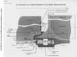
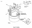
The SRM aft field joint configuration is illustrated in Figure 3. Flow disturbances were investigated as a possible cause of abnormal heat transfer. The following is a discussion of the effects of flow disturbances on convective heat transfer in the SRM.
(1) Axial Vortices
Under normal conditions, axial swirl and axial vortex pairs do not exist for reason of axial symmetry. Swirl can conceivably originate from uneven burning in the forward part of the forward motor segment. It would be restricted to a stream tube near the motor axis, causing a slight helical twist of the streamlines. It would have no effect on structural heating. Vortex pairs could originate from uneven burning of axial strips of the burning surface. They should be weak, have no effect on the combustion process, be restricted to the central motor cavity, and have negligible effects on structural heating.
(2) Circumferential Vortex Rings
Circumferential vortex rings exist in the space (or slots) between the propellant of the motor segments of the SRM from about t - 47 seconds to the end of burn; i.e., when the exit area of the slots exceeds the surface area of the axial burning faces. They are a. normal feature of all SRMs and drive the convective heat transfer on the surfaces they touch. No reason can be identified why they should have been different in the right motor on STS 51-L.
(3) Internal Acoustics
The noise level in the SRM cavity is of the order of 175 db, dominated by cavity noise, and decreasing with increasing burn time. Plane, coherent sound waves of this sound pressure level produce wave-induced velocities of about 1 percent or less of the mean gas velocity; a standing wave would only double this value. The actual random waves produce velocities of a much smaller magnitude. The convective heat transfer is therefore not affected by the acoustic noise level.
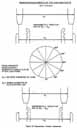
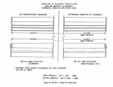
A failure due to increased convective heating on the joint is improbable. Therefore, assumed types of insulation flaws were examined to determine the probability of overheating the O-ring or joint with nominal convective and radioactive heat transfer. Figure 4 gives an example of the magnitude of an insulation flaw which would be required in order to result in a failure prior to 60 seconds. A convective heating rate (based on "char-motor" data and an observed erosion rate in the SRM aft field joint slot of 5.4 mils per second) of 380 Btu/ft2 -sec and a radiation heating rate of 480 Btu/ ft2 -sec were assumed and incorporated in a two-dimensional thermal model of the joint. The insulation thickness which would erode away at 5.4 mils per second to produce a failure at 60 seconds is shown in Figure 4. A flaw of this magnitude is unlikely and would be easily detected. Testing conducted by Morton Thiokol as part of this failure investigation indicated O-ring failure near 1,000°F. The primary and secondary O-ring temperature transients are shown in Figures 5 and 6 for the insulation flaw in Figure 4.
Insulation flaws at the field joint must be large to create a failure in 60 seconds. However, a relatively small flaw-in the forward-facing inhibitor could cause ignition of the propellant behind the inhibitor which would burn back prematurely. It is not probable that a failure of the castable inhibitor would cause a flight failure since this inhibitor normally burns away in approximately 13 seconds.
The effects of a forward-facing inhibitor failure was evaluated by assuming a 1-inch-diameter hole at the base of the inhibitor as shown in Figure 7. Analysis indicated that the change in motor internal pressure resulting from this failure would probably not be detected. However, an extremely high erosion rate would be required (as compared to observed values) to produce a burn through of the membrane by 58 seconds. In addition, the assumed flaw is unlikely since the inhibitor is constructed by vulcanizing eight individual plies and subsequent damage of the magnitude required is improbable and would be easily detected.
Other analyses conducted in support of assessments of this scenario are reported in Appendix B.
c. Findings
No credible failure mode based on inhibitor or insulation flaws or increased heating has been identified which results in a case membrane or joint burn through in 58 seconds and also reproduces flight data and visual observations. In addition, this failure scenario requires an independent and unrelated event to explain the smoke observed at 0.678 seconds. This scenario is judged to be improbable.
![Figure 4. Assumed Insulation Flaw [top].
Figure 5. Primary O-Ring Temperature for Assumed Insulation Flaw of Figure 4 [bottom].](https://www.nasa.gov/wp-content/uploads/static/history/rogersrep/v2l60s.jpg)
![Figure 6. Secondary O-Ring Temperatures for Assumed Insulation Flaw of Figure 4 [top].
Figure 7. Assumed Inhibitor Flaw [bottom].](https://www.nasa.gov/wp-content/uploads/static/history/rogersrep/v2l61s.jpg)
[L62] 2. LH2 Leak Resulting in SRM Case Membrane or joint Failure
This hot gas leak failure scenario is discussed in the External Tank Report, Section IV.I.2. Based on the rationale presented therein, which draws on build data, prelaunch data, flight data, and analysis, this scenario was judged to be improbable.
3. Assembly Conditions/Anomalies
a. Scenario Description
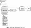
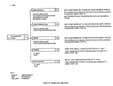
This hot gas leak failure scenario hypothesizes damage of the right SRM aft field joint and/or O-rings during mating, leading to a hot gas leak during flight or other assembly anomalies which could have contributed to the failure. Possible event paths leading to joint/O-ring failure are shown in Figure 8.
Several events and photographic coverage of the STS 51-L mission, which depicted a hot gas leak in the region of the aft center segment to aft segment field joint of the right SRM, provided the initial rationale for this scenario. A review of the right aft SRM field joint dimensions at mating revealed that an interference fit resulted in the quadrant where the leak was observed. This condition could have resulted in generating contaminants (metal shavings), physical damage of the O-ring, or stress-related failure of the clevis leg. It also created a condition of near metal-to-metal at the clevis and tang sealing surfaces which could cause essentially complete compression of the O-rings into their grooves. The effect of this condition (max O-ring squeeze) is also involved in other scenarios and is discussed in subsequent sections of this report. Additional data were provided from an investigative activity to assess dimensional changes associated with case use. This activity revealed the possibility that growth was occurring in the critical sealing diameters of both clevis and tang with the greater growth occurring in the inner clevis leg. This could further increase the degree of interference known to exist as well as maximum squeeze on the O-rings.
The related events supporting this scenario included SRM stacking reports and procedures indicating difficulty in mating as a result of shipping-induced case segment ovality, postflight inspection reports indicating mechanical damage or pinch marks on field joint O-rings from SRM 14A, one ground test assembly incident of a damaged primary O-ring, and a reported incident of metal shavings in the sealing area after case segment disassembly. The incident involving metal shavings, although not directly relatable to flight assembly, was reported in TWR 13-515, covering the results of an investigation of DM-5 O-ring leak check failure.
Six major activities were initiated to assess the validity of Scenario 3. A detailed technical discussion and relevant findings relating to each activity are provided. A review of build records, including discrepancy reports, was also initiated to determine if errors or omissions in these documents existed. The review of SRM build records did not reveal any irregularities that could have contributed to the failure of 51-L, right SRM.
b. Investigation
(1) Stacking Conditions for 51- L and Other Flights (Shipping, Handling and Assembly)
There was difficulty in mating the right SRM aft field joint on 51-L. As a result of this report, a review of stacking procedures was initiated to determine the conditions surrounding the assembly of this joint and others. Data for the review consisted of KSC stacking records and pre-mate ovality measurements for the 51-L right SRM field joint and most other field joints assembled to date.
The SRB case segments are transported to KSC in the horizontal position resting in a shipping fixture with the tunnel (located at 90°) in the twelve o'clock position. Because of the flexibility of the segments, some ovality is induced with the major axis of the ellipse in the 0°/180° direction. Also, because of nonsymmetrical placement of the aft skirt holddown posts, ovality is induced in the aft casting segments, with the major axis in the 90°/270° direction. Thus two ovals must be assembled with their major axis out of phase by 90°.
Experience and analysis have shown that the segments can be mated and various techniques have been developed. The four-point handling beam was developed to lift and recontour the cases (Figure 9). This is accomplished by lifting the case segment and comparing tang end ovality measurements with those of the clevis to which it is being mated. The handling beam has provision to release two of the four pickup points thus permitting the weight of the loaded case to induce slumping and tend to round according to which two pickup points are released. Over time, while hanging from the crane, the case will tend to release some of the ovality induced by the shipping fixture. There is a requirement that prohibits mating flat-to-flat and the mating procedures state that ovality cannot exceed 0.250 inch in the positive direction (tang outer diameter greater than clevis outer leg inner diameter) to prevent flat-on-flat while attempting to lower the tang into the clevis. However, no requirement exists for controlling the situation which would exist for the tang inner diameter being less than the inner clevis leg (negative direction. Figure 10). This situation existed for the right SRM aft field joint and to a lesser extent for other STS 51-L joints.
Should the handling beam be unable to achieve conditions suitable for mating in a reasonable time (hours), a further attempt to round can be made using a rounding tool. (Reference Figure 11.) The rounding tool is essentially two outside fitting chocks with a connecting rod through two opposing tang pin holes. The rod is tensioned using a small hydraulic pump until the segment is brought into the approximately correct diameter for mating. The rounding tool is removed just before mating.
Use of the crane hoist fixture and the rounding fixture as currently designed do not always correct all ovality sufficiently for mating. Some difficulty in assembly is still experienced, particular1y with the aft field joint. The 51-L right SRM aft and 61-G left SRM aft field joints were among the most difficult to assemble of any attempted to date because of excessive ovality.
The right SRM aft field joint of 51-L required numerous attempts to match the tang ovality with that of the clevis. Following the initial four-point lift, three two-point lifts were employed and then the rounding tool was used. The last measurement before mating indicated a positive ovality measurement of 0.216 inch, only 0.034 inch from the maximum allowed by procedure. Negative ovality measurements were 0.334 and 0.393 inches at the 90°/270° and 120°/300° positions respectively, placing the tang end in contact with the inner clevis leg and O-rings at these locations. Because of the extreme ovality at mating, the possibility of the flat end of the tang resting on the flat top of the inner clevis leg before sliding down the taper into the slot, cannot be discounted. Negative measurements in the range of 0.340 to 0.355 inches can result in flat-on-flat if the segment center lines are not co-aligned within approximately 0.200 inch. Testing has demonstrated that this mating mode can generate metal shavings which in turn could compromise performance of the O-ring seals.
Although the right SRM aft field joint was the only one on 51-L requiring use of the rounding tool to achieve mating, other field joints also exhibited ovality with varying degrees of negative dimensions. The maximum negative ovality at mating for each of the remaining five field joints ranged from 0.178 to 0. 374 inches. Some of these conditions place the end of the tang in direct contact with the O-rings on insertion and result in near metal-to-metal contact at the sealing surfaces after assembly.
(2) Dimensional Assessment of Refurbished Cases
Case dimensions in the region of the tang and clevis are critical to calculations of O-ring squeeze and subsequent seal performance. It was determined in the early phases of the investigation that tang and clevis sealing surface diameters are not reestablished after case use, prompting the concern that changes in these critical.....
[L65] ....dimensions may have occurred.
To address this concern, two case segments (SN0000056 with four uses and SN00022 with five uses) were returned to Rohr for dimensional assessment. Measurements including Pi tape of the sealing surface diameters were made with the segments mounted in the machining lathe. The same procedures and equipment originally employed by Rohr prior to initial shipment of these segments to MTI, were used. These same measurements were also recorded with the segment in the unrestrained condition using the same equipment and procedures employed in initial new case machining buyoff. Case SN0000022 exhibited a 0.028-inch increase in diameter at the tang sealing surface and an increase of 0.034 inch in diameter at the clevis sealing surface. Case SNO000056 exhibited an increase of 0.022 inch and 0.032 inch at the tang and clevis sealing surfaces respectively. (See Figure 12 for tabulation of these dimensions and deltas between new case measurements and measurements taken on used cases.) Figure 13 presents a ratioed extrapolation of the growth experienced on Case Segment SNOO00056 with four prior uses to the 51-L aft field joint containing a tang end with one prior use and clevis end with two prior uses. This analysis disclosed a potential of a 0.002inch larger diameter clevis than tang resulting in an interference fit.
A similar analysis performed on the other 51-L field joints revealed a potential interference fit on the right SRM centerjoint of 0.005 inch and a near interference fit (0.0005-inch clearance) on the right SRM forward field joint. The joints on the left motor all exhibited a clearance greater than 0.005 inch, assuming concentricity. The greatest increase in clearance was noted on the left SRM forward field joint. Again, assuming concentricity, the clearance increased from 0.008 inch, as calculated from the original machined dimensions, to 0.013 inch using the ratioed extrapolation of growth based on case segment reuse.
(3) Sructural Analysis of 51-L Right SRM Aft Field joint Mating
Analysis of the 51-L right SRM aft field joint mating conditions was performed because of the difficulty experienced in assembling this hardware. Specifically, the study was structured to determine the deflections and stresses experienced during mating the right SRM aft center segment to the aft segment and an analysis of the fracture mechanics of the O-ring groove to determine the criticality of a flaw in the highest stressed area; i.e., the maximum size of a flaw that would not fail under the life cycle history of the 51-L case segment. Included in this analysis was the point load needed to deflect a suspended segment to the side by 0.200 inch and the maximum stress on the case clevis this causes. Additionally, the study was structured to determine the load/deflection relationship required to assemble an ovalized tang to an ovalized clevis. Finally, the study addressed an occasionally encountered condition where the tang rests on top of the inner leg of the clevis on one side and slips down into the clevis groove 180° opposite. The analysis determined the loads involved and if damage to the assemblies could occur.
The fracture mechanics analysis showed that flaws 0.21-inch deep x 2.1-inch long in the secondary O-ring groove will survive over 100 uses without any substantial growth. Flaws of this size would be readily detectable by the magnetic particle inspection performed on all case segments. The detectability limit specified for this inspection is a flaw length of 0.1 inch. The load to deflect a suspended segment over 0.2 inch in the horizontal direction was calculated to be 75 pounds and causes a maximum stress in the secondary O-ring groove of only + 966 psi. Resting a segment on the top of the inner leg of the clevis and allowing the segment to rotate down 0.7 inch to the outer leg of the clevis on the opposite side results in an 8,000-pound vertical load on the inner leg. This produces a maximum compression stress of 62,000 psi in the primary O-ring groove. Applying a horizontal point load of 1,000 pounds at the top of the inner leg of the clevis produces a maximum stress of + 12,871 psi at the secondary O-ring groove.
The results of the analysis indicate that the stresses induced during the mating operation were low and would not have resulted in hardware damage. Also the stresses would not have resulted in significant growth of an undetected flaw of a length substantially greater than that which is detectable by the inspection techniques employed.
(4) Testing to Simulate 51-L Right SRM Aft Field joint Mating
This test program was designed to simulate probable conditions during the assembly of the right SRM aft to aft center segment field joint of STS 51-L. Careful attention was focused on the efforts of controlled assembly conditions on the O-rings and the mating metal surfaces of the tang and clevis. Testing included laboratory studies with a 1-foot section of tang and clevis and full-scale studies using fixtures at MTI.
A section of a field joint consisting of a tang and clevis (each approximately 12 inches x 13 inches) was secured in a tensile test machine (50,000-pound capacity) with two rigid fixtures. Two lengths of O-ring material (taken from flight quality sections of SN0001669 and SN0001777) were held in place with fasteners at point's tangent to the arc of the clevis and were tensioned within a predetermined range. The tang was positioned in its fixture above the clevis in a specific position for each test to simulate several different probable combinations of mating surface interference and relative angles. The clevis was then raised into the tang by the tensile machine drive mechanism. Various measurements and observations were made before during, and after the test. Any damage to O-ring or metal surfaces or any occurrence that would tend to increase the probability of damage was noted.
Two significant findings were made. First, metal slivers were generated under mating conditions in which the flat end of the tang overlapped the flat end of the inner clevis leg by 0.005 to 0.010 inch before encountering the guiding taper. (Considering some change in ovality may have occurred between the time the last measurements were made on 51-L and final mating, such a condition could have existed for the right SRM aft field joint.) The metal slivers in turn were carried into the joint and deposited on and around the O-rings. The second significant finding, was that the length of the O-ring segments increased as the tang entered the clevis and compressed the O-ring diameter. This increase in length averaged 4.1 percent. The implication of this finding is that canted tang entry in a full diameter segment could "chase" the O-ring around the circumference, resulting in it bulging out of the groove on the opposite side, thus making it vulnerable to damage.
Full-scale tests using fixtures at MTI were conducted to further assess conditions of O-ring elongation noted in the laboratory. These tests were structured to determine if insertion of the tang into the clevis, when the tang is tipped relative to the clevis, will cause the O-ring to accumulate excessive slack such that it will locally extend beyond the groove and be damaged during assembly. Initial tests were conducted with a short stack fixture. This fixture is a full diameter representation of the joint area in the SRM. The results of these tests proved inconclusive in that the fixture was too flexible to induce any observable length change in the O-rings. Further tests employing a more rigid test fixture and/or SRM hardware are under consideration.
(5) Testing to Assess the Effects of Assembly-Induced Contamination on O-ring Sealing
These tests employed metal contaminants to simulate those generated in the segment mating tests. The tests were structured to determine if assembly-induced metal shavings, positioned between the O-ring and sealing surface, could pass a static leak check but fail under dynamic loading. Tests were designed to use the subscale static and dynamic blowby fixtures and the full-scale short....
![Figure 11. Rounding Tool [top].
Figure 12. Case Dimensional Reassessment at ROHR [bottom].](https://www.nasa.gov/wp-content/uploads/static/history/rogersrep/v2l66s.jpg)
[L68] ....stack test fixture. The data show that all simulated metal contaminants tested produce essentially the same results within the variability of the data; the thickness of metal contaminant, which first passes the 50 psig level check, is in the 0.001 to 0.003 inch range. Tests to determine if this size contamination will compromise the seal under dynamic loading have not been completed at the time of this writing.
(6) Destacking STS 61-G
It was also determined that STS 61-G, the last vehicle to be stacked and still in the Vertical Assembly Building (VAB) at KSC. experienced similar mating problems with the left SRM aft field joint as did STS 51-L. STS 61-G afforded an unusual opportunity to look for assembly-related anomalies. Accordingly, a plan for destacking 61-G was prepared and forwarded to KSC.
The plan outlines specific actions to be taken during destacking to support an assessment of conditions of the motor and case field joints. The requirements identified were incorporated in specific destacking instructions issued by KSC. The plan includes a series of dimensional inspections, visual observations and assessments of hardware conditions with the operations sequenced to maximize data collection. The destacking operations are underway and this report will be augmented to incorporate the results of the destacking when completed.
c. Findings
Analysis indicates that the stresses induced during the mating operation would not have resulted in hardware damage nor would they have resulted in significant growth of an undetected flaw significantly larger than would have been detected by the inspection conducted.
Tests conducted in support of this specific scenario investigation did not result in damaged O-rings; however, such damage has been documented previously in ground test motor reports. The potential for O-ring damage due to "chasing" during assembly has not been adequately tested at this time. Such tests are under consideration. Metal shavings were generated during simulated mating tests and further testing demonstrated that small metal contaminants in the critical seal area could not be detected by the standard SRM leak check. Considering the conditions which existed during mating and reports of prior observations, the possibility that contamination was generated and could have contributed to a degraded seal cannot be dismissed. Although not totally unique to the right SRM aft field joint, the mating condition that could cause seal damage and/or contamination at assembly were more severe at this joint. Further, the location of the joint failure (burn through) was in the same circumferential location as the maximum interface at mating.
The dimensions taken during the mating operation indicated that a metal-to-metal fit existed in the quadrant where the leak was observed. This assembly condition could have been a contributing factor to the leak when combined with other conditions which existed. Such conditions will be treated in subsequent subsections.
4. Scenario 4: Primary O-Ring Blow-by or Low Temperature Effects
Hot Gas Leak Scenario 4 is a multi-branch scenario consisting of possible combinations of effects necessary to breach both primary and secondary O-rings. The common element of the scenario is primary O-ring blowby and/or low temperature effects on the primary O-ring. The four branches following the common element are 4a, Secondary O-ring Defect; 4b, Ice in joint: 4c, Leak Check Port Leaks; and 4d, O-ring Actuation Time Delayed by Low Temperature. Each branch will be discussed in subsequent subsections.
Following SRM ignition, internal pressure in the motor case causes structural deflection (rotation) of the joints in a direction that reduces the compression on the O-rings. This behavior is quantified in the analyses and tests reported in Appendix B, Part A. The sealing performance of the O-rings under this condition, as influenced by low temperature, is the subject of both the Scenario 4 common element and Branch 4d. Although joint geometry causes the primary O-ring to be more likely to experience blow-by than the secondary, the basic phenomena and method of disposition are common to both scenario blocks; therefore, a common discussion will be provided in subsection 4d.
Two primary mechanisms of this set of scenarios existed for all six SRM field joints on 51-L, specifical1y the low temperature of the O-rings and the joint rotation. The joint temperatures at launch were determined to be essentially the same (for all or a portion of the circumference) for all six joints. Joint rotation (seal gap opening due to motor pressurization) exists for all joints, although it is somewhat greater for the center and forward field joints as opposed to the aft field joints. Another important variable is the degree of O-ring squeeze. Tests and analyses indicate that squeeze conditions, which cause the O-ring to fill the groove to such an extent that the O-ring is compressed against the sides of the groove, are detrimental to sealing at low temperatures. This condition also existed to varying degrees on several joints.
a. Scenario 4a: Secondary O-Ring Defect
(1) Scenario Description
This scenario hypothesizes that there is blow-by of the primary O-ring and then leakage past the secondary O-ring due to an O-ring defect that existed prior to assembly.
(2) Investigation
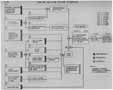
This scenario was investigated when closeout photos of the right SRM aft field joint showed a suspect secondary O-ring. The investigation was conducted by an analysis of closeout photographs, review of records and review of results of special inspections and tests. (See Figure 14, Scenario 4a Logic Chart.)
Eleven closeout photographs were taken around the right SRM aft field joint showing the primary and secondary O-rings and other features of the clevis. These pictures were examined to determine if any damaged or defective areas existed in the O-rings or if any contamination existed in the joint or on the O-rings. Detailed examinations of the closeout photos were made using digital enhancement techniques. Laboratory experiments were performed to duplicate features found in the photographic analysis.
Assembly records were reviewed to establish the serial number of the O-rings used on STS 51-L. MTI receiving inspection records were reviewed to determine results of inspections and reject-history of all O-rings processed at MTI. Vendor process records were also reviewed to determine compliance with plans and specifications. The intent of this record review was to determine the probability of a defective O-ring not being detected prior to assembly.
All O-rings in inventory at MTI-Wasatch, VAFB, and KSC were reinspected to determine their compliance with specification requirements. Each O-ring was reinspected using a standard micrometer equipped with a 1/2 inch foot to measure the 0.280-inch diameter and a special tool to measure the 142-inch diameter. This same equipment had been used for the original acceptance inspection. During reinspection, the 0.280-inch diameter was measured every 9 inches in two planes. It was measured every 2 to 4 feet in only one plane during the original acceptance inspections. Each O-ring was also reinspected using a laser micrometer. This instrument provided continuous diameter measurements with a 0.007-inch measuring team width. Measurements were taken in four planes. All O-rings were also X-rayed to determine if voids and inclusions were present.
Color prints of the closeout photographs became available a few days after the incident. These photographs were not of engineering quality and little could be determined by direct inspection of the prints. However, an interesting thickening of the [L69] dark space between the upper surface of the secondary O-ring and the lower edge of the land was noted together with some notable streaks in the same area on both the secondary O-ring and the land. This print with supplemental engineering information was sent to the Los Alamos National Laboratory (LANL) for enhancement and mensuration. They, in turn, arranged for the mensuration to be accomplished by the National Photographic Interpretation Center (NPIC). Their report is attached as enclosure to MSFC Test Report 9. Mensuration data of the dark spaces indicated a gradual thickening of about 0.015 inch and a subsequent decrease to about 0.006 inch extending over about 0.5 inch of O-ring length. Note that these measurements were made after the image was rotated and the perspective corrected. These data suggested a possible O-ring defect. No other notable items were found in any of the closeout prints.
Since the mensuration and enhancement was made from a poor print of the closeout photo, fine details were not perceptible, having been lost in the reproduction process. The original negative was obtained and sent to LANL and NPIC for enhancement. The NPIC report of this enhancement and mensuration is contained in MSFC Test Report 9. There was a dramatic increase in quality of the print from the original negative. More details were available. The dark space gradual thickening was changed significantly. The upper edge of the dark space was found to contain two abrupt discontinuities which are faithfully mapped to the lower edge of the dark space, indicating that what was observed on the O-ring was a shadow of irregularities on the lower edge of the land caused by grease.
To reproduce the features seen in the photograph, a curved 3-foot-long section of the inner wall of the clevis was fabricated to nominal dimensions. This fixture was used for photographic investigations of the grease patterns and O-ring defects. Grease was applied to the metal plate using gloved hands. With relatively light coatings of grease, structures or ridges of about 0.005 inch height were easily and normally developed. Heavier coatings of grease produced larger structures. These data proved that small structures could be created on metal surfaces such as the O-ring land in the normal O-ring installation process without violating the process.
Examination of the remainder of the digitized and enhanced closeout photographs revealed another artifact, a circular structure about 0. 15 inches across. Tests proved that reasonably similar structures could be created in the grease without violation of the joint O-ring installation procedures. This artifact was concluded to be a grease structure and not contaminant.
A detailed study to understand and review the O-ring process flow was conducted. This study indicated that the 0.280-inch diameter of each O-ring is measured by MTI and MTI vendors at approximately 100 places prior to final acceptance. It is highly unlikely that a major defect would escape detection by this system. A review of O-ring receiving inspection history at MTI was conducted to determine the results of inspection of the O-rings used on 51-L and to determine the results of inspection of the O-rings received by MTI. Receiving inspection records indicate that the right SRM aft field joint secondary O-ring contained three splices (five allowed) and one repair (20 allowed). The primary O-ring contained three splices and five repairs. It was discovered that in March of 1985 a revision was made to the MTI receiving inspection plan that resulted in 2 of 24 MTI inspection steps being changed from direct buyoff to verification through vendor certification. Also, three of seven Air Force Quality Assurance inspection steps were deleted by mistake. The secondary O-ring in the right SRM aft field joint in 51-L plus six other field joint O-rings in 51-L were inspected to this less strenuous plan. Inspection steps associated with the 0.280-inch diameter were not affected by this change. Details of this inspection planning change is contained in Table 1.
A summary of O-ring receiving inspection history was reviewed to determine if O-rings had been rejected at MTI for diameter problems. It was found that 32 case O-rings had been rejected since 1978. None of these were rejected for the 0.280-inch diameter requirement. Seventy-five percent of these rejects were associated with dimensions of the scarf joint. Each scarf joint is measured at MTI receiving inspection. These data reflect a low total reject rate of 1.8 percent which indicates a good quality product being supplied by the vendor.
A review of records at Parker Seal Co. did reveal a records traceability problem associated with the O-ring batch containing the subject secondary O-ring. Parker Seal Co. has supplied O-ring material for the STS program since 1978. During this period, they have supplied material with 14 different combinations of formulation and processes. These combinations are shown on Table 2. The Parker Seal Co. was unable to produce records that would validate the batch of material used to fabricate the subject secondary O-ring. Although the exact formulation is unknown, it is known that it is one of the acceptable formulation used by the Parker Seal Co. Samples of O-ring material from this batch have been tested at MSFC for requirements of MILR-83248 and found to be in compliance.
All O-rings in inventory at MTI, KSC, and VAFB were reinspected using the same inspection equipment and acceptance criteria used when initially accepted. The 0.280-inch diameter was measured every 9 inches in two planes. Eight of 190 O-rings inspected were rejected. The worst out-of-tolerance condition found was a nine inch length that was 0.003 inches undersize. The average diameter obtained from the 18,000 measurements was 0.2810 inch with a standard deviation of 0.0013 inch. The average diameter ± 3a [standard deviation] is 0.2849 and 0.2771 which is within the specification requirements of 0,285 and 0.277. Statistical analysis indicated that the process will meet the specification requirements.
The inventory O-rings were also reinspected using a laser micrometer. This instrument has a 0.007-inch measuring beam arid will provide measurement to five places when calibrated with gage pins.
|
Rev 12 (SRM 25B Primary) |
|
|
Prior S/N 1535 |
|
|
| |
|
NOTIFY AFQA |
|
|
VERIFY PACKING AND MARKING |
|
|
AFQA INSPECT FOR SHIPPING DAMAGE |
|
|
RECORD P/N, S/N, REV'S AND ECO'S |
|
|
MTI INSPECT FOR SHIPPING DAMAGE |
|
|
RECORD VENDOR'S ID |
|
|
VERIFY ACCEPTABILITY OF VIP |
|
|
VERIFY PRESENCE OF CERT AND CONFORMANCE |
|
|
AFQA REVIEW AND VERIFY CERT |
|
|
VERIFY TIME FROM CURE |
|
|
VERIFY RUBBER IS MIL-R-83248 |
|
|
VERIFY 5 SPLICEJOINTS MAX** |
|
|
VERIFY NO MORE THAN 20 REPAIRS |
|
|
VERIFY LESS THAN 1 REPAIR/FOOT |
|
|
AFQA VERIFY 5 SPLICE JOINTS MAX |
|
|
RECORD QUANTITY INSPECTED AND ACCEPTED |
|
|
JOINT MUST BE BONDED 100% OF SURFACE |
|
|
VERIFY MISMATCH AT JOINT.010 MAX** |
|
|
AFQA VERIFY .010 MISMATCH |
|
|
VERIFY VENDOR DATA SUPPORTING NOTE 6** |
|
|
VERIFY JOINT SURFACE FINISH** |
|
|
VERIFY 20 YEAR SHELF LIFE |
|
|
RECORD CURE DATE |
|
|
VERIFY LONG TERM PACKAGING |
|
|
VERIFY NO STAPLES IN PACKAGE |
|
|
VERIFY VOID OR DISCONTINUITIES PER MIL-STD-413** |
|
|
AFQA VERIFY VOIDS OR DISCONTINUITIES |
|
|
VERIFY 142.000" "A" DIAMETER |
|
|
AFQA VERIF ' Y 142.000-"A" DIAMETER |
|
|
VERIFY .280" DIA AT SCARF JOINTS*** |
|
|
VERIFY.280" DIA OF O-RINGS |
|
|
AFQA VERIFY .280- DIA OF O-RING |
|
|
Comb |
. |
Formulation |
| |
|
. | ||||
|
A |
3M BASE ONLY |
Fe2O3 |
NO DISPERSIONS |
BANBURY |
|
B |
DP1 BASE ONLY |
" " |
" |
. |
|
C |
3M/3M 75/25 |
" " |
" |
. |
|
D |
DP/3M 75/25 |
" " |
" |
. |
|
E |
3M/3M 75/25 |
" KENRICH2 DISP |
. |
" |
|
F |
3M/3M 75/25 |
" " |
OPEN MILL |
. |
|
G |
3M/3M 75/25 |
" RM7573 CHEMRITE4 |
. |
" |
|
H |
3M/3M 75/25 |
BaSO4 |
NO DISPERSIONS |
" |
|
I |
3M/DP 75/25 |
" " |
" |
. |
|
J |
DP/DP 75/25 |
" " |
" |
. |
|
K |
DP/3M 75/25 |
" " |
" |
. |
|
L |
DP/3M 75/25 |
Fe2O3 |
" |
. |
|
M |
UNKNOWN 75/25 |
BaSO4 |
" |
" |
|
N |
UNKNOWN 75/25 |
UNKNOWN |
UNKNOWN |
UNKNOWN |
[L71] The O-rings were measured in four planes. This technique indicated that approximately half the O-rings had out-of-tolerance conditions in local areas, primarily at scarfjoints and repair areas. The worst case was again 0.003 inch undersized. All O-rings were smooth and continuous with no abrupt discontinuities.
To determine if subsurface voids were present. all inventory O-rings were X-rayed. Very few voids were detected, but low and high density inclusions were found. All O-rings contained high density inclusions and approximately 50 percent contained low density inclusions. Most of these inclusions measured from a few thousandths to 0.030 inch but a few were as large as 0.075 inch. Samples of the material found in the inclusions were examined by scanning electron microscope and energy dispersive analysis of X-rays. The low density indications were determined to be an aromatic resin and those of high density were barium sulfate brass, iron, sulfur, or calcium silicon. These inclusions are a combination of contamination and poor mixing. The scarf joints showed up as low density bands due to the absence of barium sulfate in the adhesive material. Voids inclusion or unbonds were not visible in the scarf joints.
O-rings containing inclusions have been tested to determine their effect on sealing function. No detrimental effects were noted. Results of this testing can be found in MSFC Test Report 1B.
(3) Findings
It was concluded by analysis of the digital and enhanced 51-L closeout photographs that these pictures do not show a damaged or contaminated O-ring. It was also demonstrated that features in the photographs, such as streaks and small structures can be duplicated in grease on a test ring using flight hardware assembly techniques.
It was concluded through reinspection of approximately 200 inventory O-rings that defects greater than 0.003 inch do not exist in O-rings that have completed final acceptance at MTI.
Based on the results of the investigative efforts. it is considered improbable that the 51-L failure resulted from an O-ring defect that existed prior to assembly.
b. Scenario 4b: Ice in joint
(1) Scenario Description
This scenario deals with the assessment of the effect of rain water being trapped in the field joints, freezing as the result of the cold temperatures the night before the launch of 51-L. and degrading the sealing capability of the joint.
(2) Investigation
Figure 15 presents the detailed breakdown of Scenario 4b into individual analysis and test tasks. Analyses are summarized in Appendix B and tests are summarized in Appendix C.
It is probable that water was in the field splice joints. Subsequent to the STS 51-L incident it was learned that water had been observed in the joints of STS-9 during destacking operations following exposure to less rain than experienced by STS 51-L. It was reported that water had run out of the joint when the pins were removed and that approximately 0.5 inch of water was present in the bottom of the clevis. STS 51-L had been exposed to approximately 7 inches of rain while on the pad for 38 days.
The ambient temperature at the pad on the night of January 27, 1986, was reported to be a minimum of 24°F and analyses show that the environment that night was sufficient to cause total freezing of water in the joints. Analysis shows that the freezing process started approximately 10 hours before launch and it took approximately 2.5 hours before all regions of the joint reached 32°F. Complete freezing of the water in the joint takes approximately 2.5 hours. Therefore, all the water in the joints should have been frozen by 7 a.m. EST and portions of all joints would have remained frozen at launch.
Analysis indicates that the volumetric expansion of water to ice is sufficient to unseat the secondary O-ring when the expansion path is blocked by a grease plug or if the cavity is filled with liquid water. For zero SRM tilt and minimum tolerances, ice can reach within 0.17 inch of the secondary O-ring and for nominal tolerances ice can be within 0.30 inch of the O-ring.
A relatively small vehicle tilt to approximately 0.3 could position water locally at the secondary O-ring. Furthermore, because a column of liquid would grow toward the O-ring during the freezing process, vehicle tilt between 0.1° and 0.2° could result in ice at the O-ring. Inertial Measurement Unit (IMU) alignment at the time of vehicle launch showed a vehicle tilt of 0.24° toward the east-south east. This magnitude of tilt is on the order that could give ice problems to the secondary O-ring: however, the tilt is approximately 180° opposite the area of prime interest on the right SRB. The history of vehicle tilt during the critical freezing period is not currently available but is being evaluated.
The water capillary forces for the clevis configuration are small. For a clean nongreased nominal steel joint the maximum rise of water above the top of the pins would be 0.15 inch in the inner clevis. This effect alone would be negligible to the 4b Scenario and therefore would be listed as improbable on the Figure 15. Scenario 4b diagram. However, if local areas were not greased it could be a contributory factor when coupled with other effects. It is of the relative magnitude which would have been required to place water/ice at the secondary O-ring when considered with the analysis results reported in the previous paragraphs.
Evaporation and condensation effects within the joint are possible. After water enters the joint and fills to some level within the inner tang/clevis cavity, the trapped air would become saturated with water vapor. Then thermal cycling of the joint (day/night cycles and weather effects) could result in condensation of the vapor to a critical region of the joint such as at the clevis groove of the secondary O-ring. However, unless contained by some intermediary; e.g., grease: upon freezing it is unlikely it could exert much force on the secondary O-ring. Within a given region or circumferential location of the joint, there is very little driving potential in the way of thermal gradients for transportation of condensing vapors. However, different circumferential locations in the joint do exhibit marked temperature differences, primarily due to the effect of locally incident solar energy. Solar heating results in approximately 20°F temperature differences across the SRB and this creates a vapor pressure difference in the order of 0.3 psid. Therefore, there is a potential for transportation of water by vapor flow from one region of the joint to another. It could furthermore be assumed that some blockage due to partial grease "dams" could prevent the condensed vapors from equalizing the liquid hydrostatic forces. The collection of water by this effect would be most likely to occur in those regions of the joint that were not subjected to direct sunlight. This includes the area of prime interest facing northwest on the right SRB.
Testing was accomplished to evaluate Scenario 4b. Thiokol conducted a "Short Stack Freeze Test (MTI 112). The basic purpose of this full-scale test was to measure clevis spread and increase the seal gap at the O-rings due to water/ice expansion with the clevis/tang cavities filled with water. The test results showed that the clevis did not spread and increase the seal gap on freezing. Although the effects were small, the measured results showed that the seal gap actually was decreased between 0.0032 and 0.0007 inch.
A test program was conducted to determine the effects of ice in the joint, MSFC Test 5. The test objective was to assess the effect (unseating) of ice formation in the gap between the tang and inner leg of the clevis on the secondary O-ring. Two different test fixtures were built both using optics for observation of the freezing phenomena through a Plexiglas simulator. Test fixture No. 2 proved to be the most useful in that it allowed observation through a Plexiglas tang into the inner tang/clevis cavity with the O-rings in place. The gap of the inner cavity for the test fixture was a constant 0.031 inch which is somewhat narrower than the nominal 0. 066 gap for a SRM field joint. Also the trapezoidal "plenum" area between the top of the pin and the secondary.....
[L73] ....O-ring was not simulated. This in no way negates the test results however, a somewhat larger water/ice stroke was obtained with the test fixture than for an actual joint. Based on the test results, water does not have to be in contact with the secondary O-ring prior to freezing in order to unseat the O-ring. In fact, a significant hydraulic pressure greater than leak check pressures may be generated upon freezing, and these pressure and/or mechanical blockages can prevent the O-ring from reseating until the ice has melted.
Tests have been conducted on the subscale dynamic test fixture at Thiokol to further evaluate this scenario. For these tests, conditions relative to squeeze and gap opening were simulated which resulted in sealing without the presence of ice at 25°F. The primary O-ring was removed and water was frozen downstream of the secondary O-ring. With ice present, the O-ring did not seal.
(3) Findings
It seems clear that if the joints had water to the level of the top of the pins, as supported from the STS-9 destack experience, then some unseating of the secondary O-rings due to freezing could have occurred on 51-L. Tests clearly demonstrated the ability of water/ice to unseat the secondary O-ring and subscale dynamic tests have demonstrated that sealing will not occur with ice under conditions which resulted in sealing without the presence of ice. Since it is unlikely that ice would be present at the primary O-ring, the combination of this mechanism with elements of Scenarios 3, 4d, or 6 as related to the primary O-ring are required. This mechanism cannot be eliminated as a contributor to the STS 51-L incident. However, the potential for this condition existed to some degree on all six joints for STS 51-L.
c. Scenario 4c: Leak Check Port Leaks
(1) Scenario Description
This scenario makes the assumption that the leak check port plug is either missing or loose along with the occurrence of primary O-ring blow-by.
(2) Investigation
The leak check port location is on the zero-degree (bottom centerline) position on the field joint between the aft and aft center segments of the right SRM as shown in Figure 16. This area is visible to cameras E-60 and E-63. Assessment of this scenario is accomplished through review of the lift-off films.
The configuration of the leak check port area is shown in Figure 3 (Section IV.A.1). Since the leak check port is on the zero-degree position on the right SRM, any smoke issuing from the port should appear to emanate from the location shown in Figure 17. Figures 18 through 23 present the location of the smoke as it was observed on cameras E-63 and E-60 during the initial phase of the smoke buildup. These figures were made on a film motion analyzer which graphically depicts the film events. As is evident from the figures, no smoke is observed issuing from the leak check port location.
(3) Findings
Based on the above findings, which show the observed smoke to be in a location inconsistent with this scenario, it was determined that this scenario was improbable. Subsequent to this assessment, a section of the right SRM aft joint tang containing the leak check port was recovered and evaluation of this hardware revealed that the leak check port did not leak and/or induce the failure.
d. Scenario 4d: O-Ring Actuation Time Delayed by Low Temperature
The phenomena and method of disposition of this element are the same as those of the common front element of Scenario 4; therefore, both elements will be discussed in this subsection.
Following SRM ignition, the internal pressure in the motor case causes structural deflection (rotation) of the joints in a direction that reduces the compression on the O-rings as illustrated in exaggerated form in Figure 24. In a successfully functioning joint, the O-ring resiliency and the forces of the increasing gas pressure cause the primary O-ring to follow the expanding motion of the metal parts so as to maintain a seal between the tang and the clevis. At the location of the secondary O-ring, the structural deflection is less than at the primary, so that under identical pressurization conditions, the secondary should be better able than the primary to follow the metal motion and maintain a seal. The 4d scenario hypothesizes that the combination of 51-L dimensions, temperature, and loads were such that both the primary and secondary O-rings did not maintain a seal and permitted a hot gas leak through the joint.
There are two paths for Scenario 4d, as depicted in Figure 25. Each will be discussed in turn.
(1) Scenario 4d-Path P Blow-by Caused by Joint Dimensions, Pressure Response, Temperature Effects.
(a) Scenario Description
This scenario path hypothesizes that for the joint deflection with as assembled dimensions, the cold O-ring resiliency and pressure actuation response of the O-rings are insufficient to maintain a seal as the joint rotates. This scenario would be consistent with a failure at ignition as would be evidenced by the observed puff of smoke at 0.678 seconds.
(b) Investigation
The process depicted in Figure 26 was used to assess and disposition this scenario. The elements and results will be discussed sequentially.
(1) Static joint Dimensions
The static joint dimensions were estimated making use of measured case dimensional data and measurements taken at assembly. The minimum initial gap was determined from analyses which examined the relative compliance of the O-rings and the metal parts. The maximum initial gap was derived from assembly data with the addition of other effects such as out-of-round influences on clevis opening. These minimum and maximum static gap data determine initial conditions for the dynamic joint deflection analysis and for dynamic tests.
Based on an examination of measured tang and clevis dimensions, the maximum static gap was determined to be 0.020 inch for the right SRM aft field joint. This provided an upper bound for dynamic tests. Assembly data indicated the potential of a zero minimum static gap whereas an assembly analysis indicated a minimum static gap of 0.007 inches. Evaluation of mating dimensions indicated that several field joints were probably near this minimum static gap condition. A minimum initial gap of 0.004 inch was used as a lower limit for testing.
(2) joint Deflection
The joint deflection as a function of pressure and time was determined by a detailed finite element structural analysis which was calibrated to joint deflections measured on a pressurized structural test article without propellant (Appendix B). Analysis extended the resulted beyond test calibration conditions to include effects of propellant and external loads. The combination of initial static gap dimensions with the pressure time history determined the minimum and maximum gap response conditions for testing the O-ring sealing capability.
The joint deflection analysis reported in Appendix B established time histories for gap opening for primary and secondary O-rings for all field joints. These data indicate gap openings of approximately 0. 029 inch and 0. 0 17 inch for the primary and secondary O-rings respectively for the aft field joint. The calculations for the aft field joint provided the basis for dynamic tests. Due to differences in motor pressure and loads, the gap opening for forward field joints is approximately 0.008 inch greater than for the aft field joints.
(3) Launch Temperature Analysis
Analysis reported in Appendix B established SRM joint temperatures at launch. While some differences exist between joints, and while the joints on the right SRM have larger.....
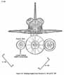


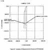
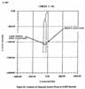

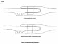

[L79] ....circumferential gradients at launch, all Joints have predicted local temperatures of 28 ± 51F. These data were used to establish lower temperature limits required for tests,
(4) Precursor Tests
Testing to disposition this scenario involved several separate test elements. Precursor tests were performed to evaluate component aspects of joint sealing behavior, and to provide guidance for higher fidelity tests. Tests MSFC 3 and MTI 111 determined O-ring resiliency as a function of temperature, duration of compression. and material composition. Pressure actuation sealing capability as a function of temperature with static joint geometry as assessed in test MTI 109 and MSFC 4E.
Consistent results from numerous O-ring resiliency tests showed a significant loss of resiliency with decreased temperature, as indicated in Figure 27. Time of compression was also influential, but to a lesser extent. The data indicate that at cold temperatures, resiliency alone is insufficient to permit the O-ring to follow the opening joint. Pressure actuation testing in a static fixture showed sealing capability at temperatures down to -10°F without joint rotation as long as positive compression is maintained.
(5) Dynamic Tests
Subscale dynamic tests which simulated the initial static gap, Zap opening rate and maximum gap openings, joint temperatures _and motor ignition transient pressure were conducted at Morton Thiokol (Test 110) and at MSFC (Test 4H). These tests evaluated the sealing capabilities of the joint under conditions which would allow the motor ignition transient pressure to be present at the O-ring to provide sealing simultaneous with the Zap opening effect. A summary of test results is provided in Figure 28. The results indicate that with a maximum initial gap of .020-inch sealing can be achieved at temperatures below 25°F while with an initial gap of 0.004 inch sealing is not achieved at 25°F and becomes marginal in the 40°F to 50°F temperature range. For the 0.004 inch initial gap conditions, sealing without any gas blow-by of the 0-rings occurred at 55°F. To evaluate the sensitivity to initial gap opening, four tests were conducted at 25°F with an initial gap of 0.010 inch. In contrast with the , tests at 0.004 inch gap, these tests resulted in sealing but did indicate some minimal blow-by of the O-rings during the sealing process. It should be noted that the test fixture used placed the O-rings at a specific initial gap (squeeze condition) uniformly around the circumference. It is not known what, if any, circumferential pressure assist might occur from areas where minimum initial gap did not exist.
(6) O-Ring Compression
Analysis reported in Appendix B indicates that if the O-ring is sufficiently compressed into its groove such that it contacts both sides of the groove, under conditions of cold temperature that causes resiliency to be so low that the O-ring does not rebound from that compressed position, the arriving gas pressure will hold the O-ring more tightly in the groove, permitting blow-by. Conversely, if initial compression of the O-ring is insufficient to make it contact the sides of its groove, the arriving gas pressure can get around the O-ring, forcing it to seal the gap.
An analysis of O-ring and groove cross section showed that for a nominal O-ring and nominal groove, the initial gap necessary to provide O-ring contact with groove sides was approximately 0.004 inch. A minimum O-ring with a maximum groove produces no side contact even with zero initial gap (hence would pressure actuate), whereas a maximum O-ring with a minimum groove would have side contact (no pressure actuation) at initial gaps lower than 0.032 inch. For the measured 51-L right SRM aft field joint groove dimensions, the gap necessary to produce side contact ranged between 0.002 inch for a minimum diameter O-ring to .020 inch for a maximum diameter O-ring. This indicates a significant sensitivity to O-ring dimension tolerances, which are not measured. The groove dimensions on other 51-L joints were very similar to those of the right SRM aft field joint. The analytical compression results are in general agreement with the test results reported above. Other effects, such as circumferential variations in O-ring compression and pressurization, could have influence on overall sealing behavior. These characteristics were not tested in the subscale fixtures.
(c) Findings
Evaluation of these data indicates that the variables considered in this scenario may have been sufficient to cause joint failure for 51-L conditions. However, the successful functioning of all 51 -L joints except the right SRM aft field joint indicates potential influence of other variables.
(2) Scenario 4d-Path 2: Blow-by Caused by O-Ring Structural Failure
(a) Scenario Description
It was hypothesized that the O-ring might overstress under cold conditions when compressed by pressure against the edge of the O-ring groove.
(b) Investigation
After examination of drawings revealed no radius specification for the downstream corner of the O-ring grooves (i.e., potential sharp corner), Test MTI 111 was conducted to evaluate possible overstress or cutting of the O-ring by a sharp-cornered groove. The compressed shape of the O-ring in a pressurized condition was examined using transparent test fixtures in Tests MSFC 6 and MTI 102. Also , laboratory tests were conducted to assess O-ring tensile and compressive stress limit, both in the parent material and at the scarf joints.
Test MTI 113 forced O-rings against razor-sharp 90 groove corners with pressure up to 1,800 psi (over twice the maximum pressure experienced on 51-L aft field joint). No structural failure was experienced and only slight marking of the O-ring resulted.
The visualization tests MSFC 6 and MTI 102, showed that even with maximum gaps, extrusion into the-gap is minimal (0.010 inch); therefore, O-ring cross sectional distortion is not large.
Lab testing (MSFC I A) of overall C-ring tensile strength yielded 1,800 to 1,900 psi to break O-rings in a nonjoint area, compared with a specification of 1,400 psi and a joint strength of approximately 78 percent of virgin material strength, compared with a specification requirement of 40 percent. An O-ring was subjected to 17,160 pounds per linear inch compressive load without damage.
(c) Findings
Based on test results cited above, structural failure of an 0-ring is concluded to be improbable.
5. Loads Exceedance
This Hot Gas Leak scenario is discussed in the Space Shuttle Systems Report, Section IV.G.4. Based on the rationale presented therein, which draws on prelaunch data, flight data, and analysis, this scenario was judged to be improbable.
6. Scenario 6: Putty Holds Pressure Off Primary O-ring
a. Scenario Description
This Hot Gas Leak scenario hypothesizes the following sequence of events:
(1) The putty upstream of the primary O-ring (Figure 3, Section IV.A.1) acts as a seal and does not allow motor pressure to seat the primary O-ring during the period of transient motor pressure buildup.
(2) The gap between the tang and clevis at the O-rings increases as the motor pressure increases during the ignition transient.
(3) The O-rings are not able to respond to track the increased gap opening and a flow path exists between the O-ring and its sealing surface.
(4) The putty seal ruptures allowing hot gas to flow underneath the O-rings.
(5) The O-ring are eroded by the hot gas and cannot maintain a seal.
b. Investigation
The tang/clevis gap opening (joint rotation) for all SRM field joints has been established by analyses and tests as reported in.....
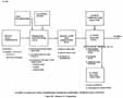
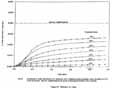
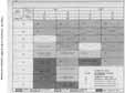
[L82] ....Appendix B. These data indicate a gap opening of approximately 0.029 inch at the primary O-ring location and 0.017 inch at the secondary O-ring during the ignition transient as the motor pressure increases to 765 psig at the SRM aft field joint. Tests conducted to evaluate the response of O-rings versus time indicate that at a temperature of 25°F (approximate temperature at launch) the O-rings would have been able to track approximately 0.005 inch of the gap opening created by the joint rotation during the motor ignition transient. (Reference Test Reports MSFC 7B and MSFC 7.) This creates a potential for flow beneath the primary O-ring if the motor pressure is not available to seat the O-ring during the ignition transient.
Prior to the Challenger incident, the pressure sealing capability of the putty had not been recognized in the design and evaluation of the joint. As a part of this investigation, evaluation of this feature of the joint damage has been conducted. Tests have been conducted over a range of conditions including: putty temperature, putty pretest conditioning to simulate the effects of environmental conditions and the dimensional variables within the joint. The tests have demonstrated that the performance of the putty as a sea] is highly variable. (Reference Dynamic Vacuum Putty Extrusion Test.) However, the results establish that the putty can maintain pressure during the ignition transient and prevent sealing of the O-ring for the full range of variables tested. For example, one test conducted with putty which had been conditioned for 10 hours at 80% relative humidity and 75°F delayed the pressure rise at the primary O-ring for 500 milliseconds at the test temperature of 75°F. Tests at 20°F with similarly conditioned putty delayed the pressurization time by 1.9 seconds. For this condition, considering the response of the O-ring and the gap opening due to rotation, a gap of greater than 0.010 inch could have existed between the O-ring and the sealing surface.
While these data indicate that the potential exists for the 0-ring not to seal, these data alone are not conclusive since the pressure provides a force tending to move the O-ring to its sealing surface. To evaluate this effect, a test fixture was designed and fabricated which allowed simulation of effective gap opening at the time of putty rupture. (Reference MSFC Cone/Piston Test Report.) Tests were conducted over a range of temperatures and also varied the assumed time of putty rupture and the initial squeeze of the O-rings. Test results are summarized in Figure 29. These tests demonstrated that sealing performance is dependent on temperature and initial squeeze. The tests indicate that sealing capability is marginal for maximum squeeze conditions (0.004 inch initial gap) at 50°F with a pressure delay of 500 milliseconds. For the temperature and O-ring squeeze conditions which existed for STS 51-L right SRM aft field joint, O-ring sealing was not achieved if the simulated time of putty rupture was delayed by 250 to 500 milliseconds.
c. Findings
Data generated during the investigation indicate that the mechanisms assumed in this scenario are potential contributors to the failure of the right SRM aft field joint. Two of the necessary conditions for this scenario are present on all six STS 51-L joints. As reported in Appendix B, the temperatures for all joints are comparable. Also, as reported in Appendix B, joint rotation is less at the aft field joint than at the two joints forward in the motor. The variable behavior of the putty would have created unique conditions which resulted in failure of this joint.
7. Case Rupture
a. Scenario Description
This Hot Gas Leak scenario hypothesizes that the failure was caused by a rupture of the case membrane.
b. Investigation
A review of structural strength, fatigue, and fracture mechanics analyses was completed. These analyses were used to determine the required mission life of the motor case and demonstrate that the case could meet the fatigue and crack growth requirements of four times the cycles and growth expected in 20 uses. Stress corrosion cracking was also considered in determining mission life.
A detailed service life history was developed to serve as the basis for assessing cumulative damage in the membrane area through mission life. The events that occur in one use cycle and repeated for the required 19 reuses are one cycle each for proof test, flight, and water impact splashdown.
Crack growth service life predictions are based on the existence of an initial flaw (oriented in the most hazardous direction) and the growth of such a flaw from all applicable mechanisms. This initial flaw is taken as the largest flaw which can escape detection by planned NDT methods. Magnetic partial inspection is used for crack-like defects on the surface of the SRS. This inspection was conducted on STS 51-L hardware after proof test Flaws greater than 0.100 inch can be detected.
Using fracture mechanics analysis, an initial flaw of 0.050 inch deep and 0.100 inch long is allowed to grow through 80 (20 uses with a safety factor of 4) "uses" in order to determine if it reaches critical dimensions before 80 uses. The wall thickness is initially assumed to be 0.459 inch minimum and decreased by 0.00048 inch after each use (for grit blast loss) until 20 uses are obtained, at which time no further decrease in wall thickness is considered. This sequence conservatively applies the fracture toughness values at 40°F for proof test and 20°F for both flight and splashdown. Crack growth due to stress corrosion is also considered during each of these events. The depth of the crack-like defects is of particular interest in assessing fracture criticality. After 275 uses, by analysis the assumed initial flaw reached the calculated depth of 0. 144 inch which corresponds to a length of 0. 288 inch. After 80 uses the calculated final flaw depth was 0.061 inch which corresponds to a length of 0.122 inch.
A proof test factor of 1.12 has been determined to be adequate to ensure that, after proof test, four missions can be flown without any flaws reaching a critical depth.
c. Findings
The aft attach segment and the lower cylinder segment of the STS 51-L right SRM motor case was successfully hydroproof tested before flight. This test coupled with inspections would have screened any critical flaw in the case membrane. The fractures mechanics analysis calculates the critical depth of a crack-like flaw in the membrane to be 0.144 inch after 275 uses in a minimum case wall thickness of 0.450 inch. A flaw of 0.010 inch length is detectable by magnetic particle inspection which is conducted after proof test. In addition, a case rupture would not be consistent with the visual observations which indicated a leak at 0.678 seconds and a sustained hot gas leak at 58 seconds. It is improbable that a case rupture initiated the incident.
B. Linear Shaped Charge Failure (Motor)
The function of the LSC system is to allow the range safety officer the capability to destroy the SRBs in the event of a safety problem involving a hazard to personnel, equipment or property. The system is installed on the forward and center segments of the SRBs. When the command is given, the system will cut the case segments causing a structural failure resulting in destruction of the motor.
There was no evidence of premature function of this system since the SRBs appeared to be intact after vehicle break-up and were subsequently destroyed by the range safety officer utilizing the Range Safety LSC.
C. Linear Shaped Charge Failure (Nozzle)
The SRB incorporates an exit cone severance ordnance ring which functions to sever and jettison a portion of the aft exit cone following completion of the flight boost phase. This minimizes water impact loads on the nozzle and the aft case segment. It also minimizes generation of debris upon water impact. The severance system is mounted aft of the compliance ring and is designed to achieve circumferential clean cutting/severance of the glass cloth.....
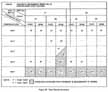
[L84] ....phenolic aft exit cone structure. The severance assembly incorporates an LSC which is initiated by a NASA standard detonator.
The nozzle appeared to be intact after vehicle break-up with normal exhaust plume and no evidence of debris in the exhaust. The LSC is well insulated and there is no history of premature firings of the system. TVC data did not identify any thrust mismatch which could be attributed to nozzle exit cone severance.
D. Propellant Detonation (External Shock Wave)
The propellants developed for the SRB program are nearly identical to proven formulations used in the Minuteman Stage I and Poseidon C-3 Stage I motor programs. Minor tailoring of the ground oxidizer and ferric oxide ratios were made to achieve desired burn rates.
The TP-H1 148 family of propellants has proven to be predictable and provides the required performance.
The motors appeared to be intact after vehicle break-up, except for the right SRM aft joint leak. There is no evidence that a propellant detonation occurred.
E. Safe and Arm Device Failure
The S&A device provides interlocking mechanical and electrical features that prevent ignition of the SRB when in the safe mode. The device also enables remote electrical arming and safing with visual position indication and provides for monitoring the electrical circuits. The arming and monitoring circuitry includes a rotary switch and electrical motor drive. Also mounted on the motor shaft is a disc (rotor) that provides a metal barrier between two NASA initiators and the booster charge. Thus, ignition is prevented electrically and mechanically when the mechanism is rotated into the "safe" position. The two initiators provide redundant means of ignition but circuitry is not redundant.
A structural failure could cause a hot gas leak resulting in a burn through in the head end of the motor. However, there was no visible evidence of smoke of flame in that region and electrical components at the head end of the motor continued to function.
F. Igniter Failure
The major components of the SRB ignition subsystem consist of an S&A device, an adapter assembly, a loaded igniter initiator chamber assembly, and a loaded igniter chamber assembly. Both chamber assemblies contain liner, insulation, and propellant and are concentrically attached to the internal side of the adapter. The S&A device is mounted on the outside of the adapter. The entire system provides a pressure tight closure for the SRM forward segment. After the SRM is armed, the igniter ignition sequence includes:
1. An electrical signal is sent from the pyrotechnic initiator controllers (PIC) to the redundant NASA Standard Initiators (NSIs).
2. Output from the NSIs bursts the barrier windows and ignites the BKNO3 granules and pelletized BKNO3 booster charge.
3. The igniter initiator is ignited which in turn ignites the main igniter which then ignites the SRM propellant grain.
Any break in this sequence would result in failure to ignite the motor. Inadvertent initiation of the sequence would result in motor ignition within milliseconds.
A structural failure could cause the igniter case or parts of it to be ejected through the motor nozzle with the potential of damaging the nozzle. There was no visible indication of smoke or flame from the head end of the motor and electronic components continued to function. A damaged nozzle would cause a step change in pressure as opposed to the gradual pressure decay on STS 51-L.
G. Flex Bearing Failure
The flexible bearing assembly consists of a flexible core contained between 136AC steel end rings. The core is a conical symmetrically laminated structure consisting of 10 spherical forged D6AC steel shims and 11 natural rubber (elastomer) pads. The end rings absorb the applied loads while simultaneously controlling bearing motion during vectoring. The elastomer pads transmit the loads between the end rings while allowing relative motion to occur between the structural members. All parts of the nozzle assembly have a design goal of 19 reuses. Bearing elastomer pads have a design goal of nine reuses. All ablative and insulation materials are replaced after each use.
The flexible bearing boot provides primary protection of the bearing core from motor heat. The boot is composed of flexible, laminated asbestos-silica filled NBR thermal layers which are bonded to glass cloth and carbon cloth phenolic end rings.
The bearing protector insulates the flexible bearing from hot gases vented into the cavity between the bearing protector and t he flex bearing boot. It is a molded and vulcanized component consisting of a flexible section constructed from silicone rubber and two glass cloth phenolic end rings. The bearing protector is designed to stretch when the flexible bearing is vectored.
A failure would cause a leak or failure within the aft skirt resulting in a possible loss of the nozzle and TVC. This would cause a thrust imbalance and a potential catastrophic failure. There was no evidence of this supported by data or visual observation in the aft skirt area.
H. System Tunnel Failure
The system tunnel is bonded to the external surface of the case segments and serves as the tunnel that houses the LSC system for the motor and all electrical cabling to transmit pressure, thermal, vibrational, vectoring and other data as well as commands to and from the motor. Failure of this system would destroy control to the TVC and interrupt all data feedback. There was no visual evidence of debris or loss of data or vehicle control. Film 207 indicates no involvement in the raceway area which is located outboard of the SRB.
I. Propellant/Liner Debond Failure
Liner is used to bond propellant to the case internal insulation. The liner formulation (STW5-2676) selected for the SRB is identical to that used on the Stage I Poseidon motors, and very similar to the liner used in Stage I Minuteman and Genie motors.
The liner functions as a bonding agent and was developed to ensure that the liner bond strength (to the insulation and the propellant) is sufficient to cause cohesive failure in the propellant. Thus, within the system, the propellant becomes the weak link and the bond strength of the liner is more than adequate.
Throughout the SRB program the liner has remained unchanged except for a slight change in the PBNA anti-oxident to eliminate some carcinogenic material. Evidence of compliance to the tensile adhesion, peel strength, and acceptance requirements per the liner specification (STW5-2676) is given by tests and inspection performed on each liner batch.
A major propellant/liner bond failure would cause a motor pressure rise with a case burn through and catastrophic failure or hole with continuous hot gas flow. Motor pressure data and visual observation do not support this type of failure.
J. Insulation Failure
The primary internal insulation selected for the SRM is silica and asbestos filled, acrylonitrile butadiene rubber (NBR), used successfully for many years in numerous rocket motor programs. The uncured rubber is laid up in layers against the adhesive prepared case and vulcanized in place in an autoclave, This permits varying the thickness to accommodate thermal gradients and erosion characteristics that differ in each region of the motor. The result is a one-piece integral insulation for each casting segment. Adhesives are used to bond rubber to metal and unlike materials to each other where vulcanization is not practical.
[L85] Several hypothesized insulation failure modes were evaluated as a part of Scenario I and are summarized in Section IV.A. 1. A failure mode was not identified which matched observed data.
A failure in the insulation would expose the case wall and cause overheating resulting in a case burn through. An insulation failure is not consistent with the initial smoke observed at 0.678 seconds.
K. Nozzle Failure
The SRB nozzle assembly is a partially submerged convergent divergent movable design containing an aft pivot point flexible bearing as the gimbal mechanism. It has an onmidirectional TVC deflection capability of ( 8 degrees in its free state but is constrained by the actuators to approximately ± 6.5 degrees. Nozzle deflection is provided by two dual-action, hydraulic-powered actuators. The actuators are attached to the aft skirt immediately below the kick ring and to the SRB exit cone actuator brackets mounted on the compliance ring.
A partial exit cone failure could cause the TVC to deviate from the geometric centerline. Visual evidence and TVC data do not support a nozzle failure.
L. Pressure Transducer/Port Failure
The operational flight instrumentation for all flight motors consists of three, 1000 psia operational pressure transducers (OPTs) to measure SRB chamber pressure. All OPTs are mounted on the igniter adapter. The mounting hardware is treated as part of the ignition system.
A failure of a transducer mounting would cause a leak in the motor head end which would cause a loss of pressure resulting in a loss of pressure data. A structural failure could also occur causing a burn through and a catastrophic failure. There was no visual evidence of a head end burn through and electronic equipment at the head end of the motor as well as transducers continued to operate.
M. Propellant Grain Failure
Historically the TP-H1148 family of propellants have had good mechanical properties and have not had grain structural problems.
A grain failure would cause increased surface area and pressure increase resulting in a case structural failure. A partial grain failure cannot be supported by observed motor pressure data and there has been no previous history of grain failure.
N. Combustion Instability
Combustion instability would cause a thrust imbalance and pressure oscillations. Flight data do not show the existence of pressure oscillations and ground data verify that the motors do not exhibit instability.
O. External Thermal Protection System Failure
The TPS consists of components and materials designed to protect external areas of the SRB from the aerodynamically induced thermal loads. This system must assure that no degradation occurs on SRB components which would compromise mission accomplishment or preclude reuseability of the hardware.
Most of the external insulation is applied to the motor segment assemblies at Morton Thiokol. The motor field joints and systems tunnel splice joints are insulated during the SRB assembly at the assembly/launch site.
Failure of this system would permit external aerodynamic heating of case or radiant heating of the exit cone from the SSME plume. Case TPS is required for recovery only and worst case analyses show that case/joint overheating to failure during ascent would not occur.
P. Electrostatic Discharge
ESD could cause early premature ignition of the propellant away from the igniter near the case perimeter resulting in a rapid catastrophic failure. The S&A device could receive a discharge that could cause initiation of the igniter. There is no evidence of such an abnormal internal pressure rise in the motor.
Review of all build records yielded no evidence indicating that anomalous conditions were introduced into the SRM which might have initiated the failure. Possible failure modes were hypothesized and evaluated for all SRM subsystems and were eliminated by flight data and photographic evidence evaluation.
Photographic data evaluation indicated that the failure was at the right aft field joint. A number of possible failure scenarios were hypothesized which might have resulted in a failure at or near the aft field joint. Analyses were conducted to evaluate the potential for a case rupture, failure due to load exceeding, increased internal heating and hypothesized inhibitor or insulation flaws. Based on these analyses, along with flight data, these possible failure modes were determined to be improbable. The possibility of defective O-rings causing the failure was evaluated by reviewing records and a thorough examination of available O-rings and no evidence was found to support this hypothesis. In addition, closeout photographs of the joint were analyzed and suspected anomalies were explained and discounted as potential contributors. The possibility of the failure being initiated by an anomaly at the leak check port was eliminated by photographic evidence and by examination or recovered hardware.
The possibility of the SRM joint failure being initiated by a hydrogen leak from the external tank was evaluated. This hypothesis was judged to be improbable based on evaluations of build records, preflight inspections, flight data and analyses and tests of simulated hydrogen leaks.
Additional potential failure scenarios were developed to evaluate failure modes and factors effecting sealing performance of the joint. The following provides a summary of the investigation results for those factors which are judged to be potential contributions to the failure.
The investigation has shown that the joint sealing performance is sensitive to the following factors, either independently or in combination:
The O-ring sealing performance sensitivity to these factors has been investigated using specific STS 51-L hardware configuration in extensive tests and analyses. The sensitivity to each factor was evaluated independently and in appropriate combinations to assess their potential to cause or contribute to the 51-L aft field joint failure.
It should be noted that most of the testing was either laboratory or sub-scale tests. In many cases the data from these tests are considered to be directly applicable to the seal performance in full scale. However, in some cases there is a degree of uncertainty relative to scaling effects and complete simulation accuracy in extrapolating the data to full scale seal performance. Where such is the case, it is noted in the discussions of each seal performance factor that follows.
A. Assembly Damage/Contamination
Possible consequences of the mating operations which could influence joint sealing performance are damage to the O-rings or contamination generation. Prior to mating, the mating segments (tang and clevis) diameters are measured; Figure 10 depicts the measurements recorded at six locations, for both the [L86] mating tang and clevis. Due to case ovality resulting from shipping and handling, positive and negative diameter differences are frequently encountered. The interference between the tang and clevis at mating is directly proportional to the magnitude of these differences. With a positive difference, interference is encountered between the tang and the outer clevis leg at mating and with a negative difference, interference is encountered between the tang and the inner clevis leg (see Figure 10). Interference with the inner clevis leg is the condition that could result in assembly damage and/or generation of contaminants. There is a requirement that prohibits mating if the flat end of the tang contacts the flat upper end of the clevis. Mating procedures state that diametrical measurements, at any of the six locations measured, should not exceed a positive 0.250 inch difference. This controls "flat-on-flat" for a case where the diameter of the tang exceeds the clevis diameter. However, it does not control the potential for flat-on-flat, or any other interference conditions, between the tang and the inner clevis leg. A "flat-on-flat" condition can exist if the tang and clevis premate diametrical measurements have a negative difference in the range of -0.340 to -0.355 inch if the segment center lines are not co-aligned within approximately 0.200 inch. This range covers clevis design dimensional tolerances. This condition existed for both right aft and center field joints with a somewhat higher probability on the aft field joint. It should also be noted that the burned hole in the recovered right SRM aft field joint tang segment coincided with the maximum measured negative diametrical difference of-0.393 inches.
A review of prior anomalies provided some evidence that mating can result in damage to the joint/seal. Postflight inspection reports indicated mechanical damage or pinch marks on a field joint O-ring from SRM 14A. In the ground test program two assembly incidents occurred which damaged primary O-rings and one incident was encountered where shavings appeared in the sealing area after case disassembly. This experience lends credence to the postulation that damage can be sustained during mating and that contamination can be present in the joint.
Testing was conducted during the investigation to evaluate the potential for mating damage and contaminant generation along with its effect on seal performance. A section of a field joint was configured in a test fixture and simulated mating operations were conducted. Most significantly, metal slivers were generated under mating conditions in which the tang flat overlapped the flat end of the clevis leg by 0.005 to 0.010 inch. The metal slivers in turn were carried into the joint and deposited on and around the 0-rings. A second significant finding from this test series was that the O-ring section increased in length as the tang entered the clevis and compressed the O-ring diameter. This length increase averaged 4.1%. The implication of this finding is that canted tang entry in a full diameter segment could "chase" the O-ring around the circumference, resulting in "gathering" (bulging from the groove) on the opposite side, thus making it more vulnerable to damage.
To understand the effects of potential contaminants on sealing performance, tests employing metal contaminants simulating those generated in the segment mating tests were conducted. The tests were structured to determine if the assembly induced metal shavings, positioned between the O-ring and sealing surface, could pass a static leak check but fail under dynamic conditions. Data show that all simulated metal contaminants tested produce essentially the same results within the variability of the data, and the thickness of contaminants which pass the 50 psig level check is in the 0.001 to 0.003 inch range. Testing is incomplete at this time to determine seal performance under dynamic conditions with this representative contamination, and therefore the possibility cannot be dismissed that contamination that could be generated by interference mating condition could pass a leak check and yet cause the seal to leak under dynamic conditions.
A second concern for assembly damage is related to structural damage to the clevis due to abnormal loading. An analysis of the right SRM aft field joint mating condition was performed to assess the induced loads relative to potential structural damage. The analysis was structured to determine the deflections and stresses experienced during mating of the right SRM aft center segment to the aft segment. These stresses were then used in a fracture mechanics analysis of the O-ring groove, the highest stressed area in the joint, to determine the flaw criticality; i.e., the maximum flaw size that would not fail under the 51-L case segment life cycle history. Included in this analysis was the point load needed to deflect a suspended segment to the side by 0.200 inch and the maximum stress on the case clevis this causes. The analysis further addressed a condition that has been encountered where the tang sits on top of the inner clevis leg on one side and slips down into the clevis groove on the diametrically opposite side.
The analysis results indicate that the stresses induced during the mating operation were low and would not have resulted in hardware damage. Also the stresses would not have resulted in significant growth of an undetected flaw substantially greater than that which is detectable by the inspection techniques employed.
B. Gap Opening
Tang/clevis sealing surface gap opening as a function of pressure and time was determined by a detailed finite element structural analysis which was calibrated to joint deflections measured on a pressurized structural test article without propellant. Analysis extends the results beyond test calibration conditions to include propellant effects propellant and external loads. The combination of initial static gap dimensions with Pressure/driven gap opening time history determined the minimum and maximum gap response conditions used for testing the O-ring sealing capability.
The joint deflection analysis established time histories for gap opening for primary and secondary O-rings for all field joints. These data indicate gap openings of approximately 0.029 inch and 0.017 inch for the primary and secondary O-rings respectively for the aft field joint. These values were used for sub-scale dynamic tests. Due to differences in motor pressure and loads, the gap opening for forward field joints is approximately 0.008 inch greater than for the aft field joints. Gap opening changes versus time are shown in Figure 30 for the aft field joints. The total gap at any time also depends on the initial static gap and on rounding effects during segments pressurization. Sub-scale tests were designed containing those variables as well as the changes in gap opening.
C. O-Ring Squeeze As Mated (Static)
As already noted, the static O-ring compression after mating is influenced by actual hardware dimensions and the degree of segment concentricity. Evaluation of these parameters for the right aft field joint for STS 51-L indicate that near metal-to-metal gaps may have existed at some locations. The difference in the true diameters of the mating surfaces measured at the factory was 0.008 inch which would have resulted in a minimum gap of less than 0.004 inch at some locations. Diameters measured just prior to mating indicated a significant ovality resulting in a lack of concentricity of the parts at mating. Across the 120° to 300° diameter (Figure 10), a 0.393 inch difference between the tang outer diameter and the clevis outer leg inner diameter existed at mating; i.e., tang diameter less than clevis diameter. This condition indicates that a maximum compression condition existed at the 300° location which is at the location where the joint leak occurred.
During the investigation, measurements were made on segments which had been refurbished and reused. The data indicate that segment circumferences at the sealing surfaces are changing with repeated use. This phenomenon is still under evaluation; however, applying the current limited data base to the right SRM aft field joint indicates that the potential for near metal-to-metal sealing surfaces was probably enhanced.
The maximum compression condition that existed for the right SRM aft field joint was not totally unique to this joint. Evaluation....
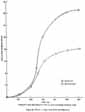
[L88] ....of the above factors indicated that this condition could also have existed on several other joints but to a somewhat lesser degree than for the right SRM aft field joint.
Analysis has shown and tests tend to confirm that the application of actuating pressure to the upstream face of the O-ring is essential to proper sealing performance; i.e., when there is a space between the upstream face of the O-ring and the upstream side of the O-ring within the groove. The existence of such a space is dependent upon the groove dimensions (width, depth and sidewall angle), the O-ring diameter, the sealing gap and temperature.
Two sub-scale dynamic test fixtures were designed and built which simulated the initial static gap, gap opening rate and maximum gap opening, and motor ignition transient pressures. These fixtures were tested over a temperature range with varying initial static gap openings. A summary of results with initial gap openings of 0.020 inch and 0.004 inch is provided in Figure 28. The results indicate that with a 0.020 inch maximum initial gap, sealing can be achieved at temperatures below 25°F, while with 0.004 inch initial gap, sealing is not achieved at 25°F and becomes marginal in the 40°F and 50(F temperature range. For the .004 inch initial gap conditions, sealing without any gas blowby past the O-rings occurred at 55°F. To evaluate the sensitivity to initial gap opening, four tests were conducted at 25°F with an initial gap of 0.010 inch. In contrast to the tests at 0.004 inch gap, these tests resulted in sealing but some minimal O-ring blowby was observed during the sealing process. These tests show sensitivity to both temperature and O-ring squeeze. However, when the results are correlated with other test and analysis data, it is evident that the most significant factor in seal performance is the ability to get actuation pressure on the forward face of the O-ring. This is directly proportional to the hardware manufacturing tolerances and the degree of maximum squeeze condition. It should be noted that the test fixture used placed the O-rings at a specific initial gap and squeeze condition, uniformly around the circumference. It is not certain what, if any, circumferential pressure assist might occur from areas where maximum squeeze did not exist. Such effects could not be simulated in the sub-scale test results reported above.
D. Joint Temperature
Analyses were conducted to establish STS 51-L joint temperatures at launch. While some differences existed between the six 51-L field joints and while the joints on the right SRM had larger circumferential gradients than those on the left SRM at launch, all joints had predicted local temperatures of 28 ± 5°F. Predicted transient temperatures for several circumferential locations on the joints are shown for the right SRM aft field joint and the left SRM aft field joint in Figures B.80 and B.81. These data are representative of other joints on the respective SRMs.
The investigation has shown that predicted launch temperatures had two effects that could potentially affect the seal performance: (1) O-ring resiliency degradation and (2) the potential for ice in the joints.
Consistent results from numerous O-ring resiliency tests have shown a resiliency degradation with reduced temperatures. Figure 27 provides O-ring recovery from 0.040 inches initial compression versus time from release of compression at temperatures ranging from 10°F to 75°F. When these data are compared with the gap openings versus time from Figure 30, it can be seen that the O-rings would not track nor recover to the gap opening at 600 milliseconds for temperatures significantly greater than those predicted for all field joints. These data show the importance of timely O-ring pressure actuation to achieve proper sealing.
It is probable that water intrusion occurred in some, if not all, STS 51-L field joints. Subsequent to the Challenger incident, it was learned that water had been observed in the STS-9 joints during destacking operations following exposure to less rain than that experienced by STS 51-L. It was reported that water had drained from the STS-9 joint when the pins were removed and that approximately 0.5 inches of water was present in the clevis bottom. While on the pad for 38 days, STS 51-L was exposed to approximately 7 inches of rain. Analyses and tests conducted to investigate this factor indicate that water in the joint will freeze under the environmental conditions experienced prior to the 51-L launch and could unseat the secondary O-ring. To determine the effects of unseating, tests were conducted on the sub-scale dynamic test fixture at Thiokol to further evaluate seal performance. For these tests, conditions relative to squeeze and gap opening were simulated which had demonstrated sealing capability without the presence of ice at 25(F. The primary O-ring was removed and water was frozen downstream of the secondary O-ring. With ice present, the O-ring failed to seal.
E. Putty Performance
Prior to the Challenger incident, the potential putty pressure sealing capability during motor pressurization had not been recognized in the joint design and evaluation. During the investigation, it became evident that several variables may affect the putty performance and in turn seal performance. Limited test data and lack of fidelity in full scale joint simulation prevented a complete engineering assessment of putty performance. Tests were conducted over a range of putty conditions including temperature at ignition, pretest conditioning to simulate the environmental effects and dimensional variables within the joint. These test results demonstrated that putty performance as a pressure seal is highly variable; and the results may be interpreted to indicate that the putty can maintain pressure during the ignition transient and prevent O-ring sealing over the range of variables tested. For example, one test conducted with putty which had been conditioned for 10 hours at 80% relative humidity and 75°F delayed the pressure rise at the primary O-ring for 530 milliseconds at a test temperature of 75°F. Tests at 20°F with similarly conditioned putty delayed the pressurization time by 1.9 seconds.
If the putty acts as a seal during the ignition transient and does not allow the motor pressure to seat the primary O-ring and then ruptures and allows motor pressure to the O-rings after the tang/clevis gap has opened, the potential exists for the O-rings not to seal. Based on the previously discussed resiliency data and gap openings, a pressure delay of 500 milliseconds would result in a flow path greater than 0.010 inch between the O-rings and the tang sealing surface. These conditions combined with conditions previously discussed which prevent O-ring activation pressure from acting on the upstream O-ring face severely restrict the seal capability.
While these data indicate that the potential exists for O-rings not to seal, these data alone are not conclusive since the pressure, when released by the putty, provides a force tending to move the O-ring to its sealing surface. To evaluate this effect, a sub-scale test fixture fabricated which effectively simulated gap opening at the time of putty rupture. These tests, simulating O-ring pressure actuation delay due to the putty holding motor pressure, were conducted over a range of temperatures, putty rupture time and initial O-ring squeeze. Test results, summarized in Figure 29, demonstrated that sealing performance is dependent on temperature and initial squeeze, both of which affect the pressure actuation capability of the O-rings. The tests indicate that sealing capability is marginal for maximum squeeze conditions, 0.004 inch initial gap, at 50°F with a pressure delay of 500 milliseconds. For the temperature and O-ring squeeze conditions which existed for several of the STS 51-L field joints, O-ring sealing was not achieved in these tests with simulated putty rupture times of 250 to 500 milliseconds.
1. A combustion gas leak through the right SRM aft field joint weakened and/or penetrated the ET hydrogen tank initiating vehicle structural breakup and loss of STS 51-L.
[L89] 2. The right RRM aft field joint was observed leaking combustion gases within the first second after ignition. The leak became clearly evident at approximately 58 seconds into the flight. It is possible that the leak was continuous but unobservable or non-existent in portions of the intervening period. In either case, it is possible that vehicle response to wind gust and planned maneuvers contributed to the leakage growth at the degraded joint location.
3. The location of the right SRB aft field joint combustion gas leak coincided with the approximate location of maximum interference between the joint tang and inner clevis leg at assembly. This mating interference can exist using approved assembly procedures, which for STS 51-L, were implemented properly.
a. Mating conditions at this location could result in maximum squeeze (minimum initial gap) on the O-rings.
b. Mating conditions at this location afforded the highest potential for undetected joint damage and/or contaminant generation which could degrade seal performance.
4. The SRM joint has design deficiencies and may not seal properly with combined variable conditions existing on the STS 51-L flight and probably led to the failure. Tests conducted during this investigation indicated that:
a. The joint sealing performance is significantly degraded as joint rotation increases the gap when O-rings are subjected to temperatures below 40(-50(F and maximum squeeze conditions in the range of .004 inches. The STS 51-L SRM joint/O-ring temperature was approximately 28(F and maximum squeeze was probable. Maximum squeeze is a significant factor because it compresses the O-ring against its groove walls prohibiting pressure actuation. This squeeze condition is aggravated by the design leak test feature that places the primary O-ring in an unfavorable position making it more difficult to pressure actuate the O-ring to its proper sealing position.
b. Putty performance in the joint seal may not be as intended by the design. Specifically, these tests indicate that putty variables, such as humidity, can delay timely actuation pressure to the O-rings. In addition, testing and STS 61-G destacking observations indicate that several blow-hole gas paths per joint can exist at motor ignition that can concentrate hot gas flow and cause the O-rings to erode. Under these conditions and in combination with other factors, joint seal performance would be significantly degraded.
c. Ice in the joint can inhibit proper secondary seal performance. There is a distinct possibility that water intrusion into the STS 51-L joints occurred since investigative activities revealed water in the STS-9 joints during a destack operation after exposure to less rainfall than STS 51-L. Conditions were such that water present in the joint would result in ice at time of launch.
5. The joint that failed was not found to be unique in that many of the factors identified and assessed during the investigation that can adversely affect seal performance were present to varying degrees in other SRM field joints on STS 51-L. It is therefore necessary to modify the SRM joint design to preclude or eliminate the effect of all these factors and/or conditions acting singularly and in combinations.