 |
|
![SIDE VIEW 2 [left] - TOP VIEW [Right]](https://www.nasa.gov/wp-content/uploads/static/history/rogersrep/v3o344bs.jpg) |
|
|
|
|
|
|
|
|
|
|
. | |||
|
|
|
|
. |
|
. |
|
| |
|
. | |||
|
Colonel Edward A. O'Connor, Jr. |
Date | ||
|
VOLUME 1 |
REPORT SUMMARIES
|
|
VOLUME 2 |
|
|
|
|
|
[O232] SOLID ROCKET BOOSTER INCREMENTAL RECOVERY PLANNING (May 1, 1986)
|
Approved: |
|
|
|
Alexander A. McCool |
|
Director, Structures and Propulsion Laboratory | |
|
NASA Marshall Space Flight Center | |
SOLID ROCKET BOOSTER INCREMENTAL RECOVERY PLANNING
PREPARED BY:
[O233] TABLE OF CONTENTS
[O234]
LIST OF PHOTOGRAPHS
[O235]
LIST OF TABLES
LIST OF APPENDICES
[O236] SOLID ROCKET BOOSTER INCREMENTAL RECOVERY PLANNING
A. SCOPE
This section describes the recovery process form the initial planning and identification of Solid Rocket Booster (SRB) components and coordination with the Navy salvage operations through the recovery to the placement of hardware in Hangar "O" or the Explosive Ordnance Disposal (EOD) Range for evaluation. The recovery operation was initiated by searching areas defined by radar tracks provided by the Eastern Space and Missile Center (ESMC) Range Safety organization with use of sonar devices. Sonar contacts were then investigated by manned or unmanned submersibles to determine if the contacts were hardware from the 51-L vehicle and to obtain video/photograhic/audio records for further identification by personnel on shore. Once hardware was determined to be useful to the investigation, plans were generated to recover and transport to shore. Safing operations (propellant disposal) and more definition of the hardware dimensions, features, etc. were then conducted for storage/other evaluation. All recovered hardware has a contact number assigned individually to catalogue each part. For the purpose of consistency, reference to SRB hardware will be by contact number with the control numbers listed in Appendix A of the Search, Recovery, and Reconstruction Team Report. The control numbers and documentation were established by the 51-L Debris Impound Area Group.
B. INTRODUCTION
The SRB Recovery Support Team was established to aid in identifying hardware located by the search vehicles. This was accomplished by placing personnel who were knowledgeable of the Shuttle hardware on-board the search vessels for initial identification (SRB, Left Hand, Right Hand, External Tank, etc. ) and by subsequent review of underwater examination records by personnel on shore. Personnel from NASA, Morton Thiokol, Inc. (MTI), USBI Booster Production Co., Inc. (USBI), and Lockheed Space Operations Company (LSOC) served on-board the search and recovery vessels. The support personnel on-board the salvage vessel (Stena Workhorse), including representatives from the ESMC Explosive Ordnance Disposal (EOD) organization, assisted in the salvage operations to ensure safety, hardware preservation, and to maintain evidence of flight anomalies.
Team members also supported the Navy Superintendent of Salvage (SUPSALV) in determining areas for search and priorities for recovery operations. Analysis of telemetry data on 51-L SRB's provided data that the right-hand motor was anomalous. In addition, early photographic and video tracking film evaluation identified the right-hand SRB as having problems. The Task Force therefore declared priorities on the Space Shuttle recovery operations to retrieve the right-hand (RH) SRB, left-hand (LH) SRB, and Orbiter to assist in the accident analysis. Attention was given to the LH SRB for the purpose of obtaining additional information to aid in the evaluation of both factory and field joint performance. In addition to the SRB components, emphasis was given to the recovery of the Orbiter, External Tank (ET), and payload (Inertial Upper Stage (IUS), Tracking and Data Relay Satellite (TDRS)).
Other activities included providing daily status reports to 51-L Investigation Team personnel at MSFC and others (Commission Task Force, news media, etc.). After recovery, team members performed inspections and documented their findings to provide accurate descriptions of the hardware.
The following paragraphs provide a report of the recovery activities performed and document the results of the SRB hardware search and recovery operations.
A. GENERAL
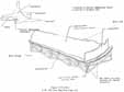
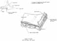
In order to understand the SRB terminology, an understanding of the components assembled on the vehicle is needed. The maneuvers of roll, pitch, and yaw are about the x, y, and z axes, respectively (reference Figure 1). Sitting in the Orbiter and looking forward, the RH SRB is below and to the right. The RH SRB is a mirror image of the LH SRB, therefore, reference datums in addition to the x, y, and z axes were established to maintain uniformity. The zero degree datum for the LH SRB is on the upper center line ( + z axis), and the zero degree datum for the RH SRB is on the lower center line (-z axis).
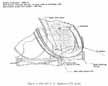
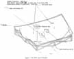
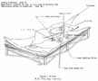
An SRB is nominally 12 feet in diameter and 149 feet long. The inert weight is 175,000 pounds, and the lift-off weight is 1,300,000 pounds. The SRB system provides the necessary structural support for the Shuttle vehicle on the launch pad, transfers thrust loads to the Orbiter and ET, and provides housing, structural support, and bracketry needed for the recovery system, the electrical components, the separation motors, and the Thrust Vector Control (TVC) system. The SRB systems consist of the forward assembly (forward skirt, frustum, and nose cap), the Solid Rocket Motors (SRM's), and the aft skirt assembly. SRB structural components are planned to be used for 20 flights (reference Figure 2).
Documentation convention stipulates that all vehicles are drawn going from the left (forward) to right (aft) thereby presenting the LH side of the vehicle. Consequently, only the LH SRB is documented; therefore, care must be exercised in reviewing drawings and illustrations to distinguish the RH SRB for the LH SRB.
B. SRB SYSTEMS
1. Forward Assembly - The forward assembly consists of the nose assembly, forward ordnance ring, and forward skirt.
a. Nose Assembly - The nose assembly includes the nose cap, the frustum structure, the frustum flotation components, and hardware for attaching the forward separation motors and nose cap thrusters. The nose cap houses both the pilot and drogue parachutes and is separated in-flight from the frustum by three nose cap thrusters. The frustum houses the main parachutes and altitude sensor assembly, provides the structural support for the forward separation motors, and incorporates flotation devices and handling hardware for water recovery.
b. Forward Ordnance Ring -The forward ordnance ring provides a plane of separation between the frustum and the forward skirt assembly. The ring houses the linear-shaped charge (LSC) used in the destruct function.
c. Forward Skirt - The forward skirt is comprised of an SRB/ET attachment fitting which transfers the thrust loads from the SRB to the ET. The forward skirt also has a forward bulkhead which seals the forward end of the skirt. The skirt provides the structure to react parachute loads during deployment, descent and towing. Internal structures are provided for mounting components of the electrical and instrumentation (E&I) subsystem, the rate gyro assembly, range safety panels, and the systems tunnel components. The skirt assembly, at completion of installation, is sealed to provide additional flotation capability.
2. Solid Rocket Motor (SRM):
a. Solid Rocket Motor - The SRM is the primary propulsive element for the Space Shuttle providing 563.5 pounds per square inch absolute chamber pressure which is equal to 1.9 million pounds of thrust vacuum. The SRM consists of: an insulated and lined segmented rocket motor case loaded with solid propellant; an ignition system complete with electromechanical safe and arm device, initiator, and loaded igniter; a movable nozzle; raceway bracketry; instrumentation; and the necessary integration hardware.
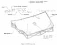
b. Scructural - The major configurations required to assemble one SRM are a forward rocket motor segment, two center rocket....
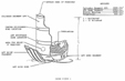
[O239] ....motor segments, and one aft rocket motor segment. Each SRM segment is comprised of two to four components. The joints of the components that are assembled, insulated, lined, and cast at the factory are referred to as factory/plant joints (reference Figure 3). A field joint is that portion of the SRM segment that is assembled/stacked at KSC to create the finished SRM (reference Figure 4). The SRM components and subsystems are physically interchangeable and replaceable. By matching the burning rates of motor segments cast in matched pairs from the same propellant lot and case weights of each segment, the performance, interchangeability, and replaceability between a flight set of SRM's can be maintained.
3. Aft Skirt Assembly - The aft skirt provides attach points to the Mobile Launch Platform (MLP) and provides support to the Shuttle on the launch pad for all conditions prior to booster ignition. The aft skirt provides aerodynamic/thermal protection, mounting provisions for the TVC subsystem, and the aft mounted separation motors. The aft skirt provides sufficient clearance for the SRM nozzle at the null position plus full gimbal travel. The aft skirt kick ring provides the necessary structural capability to absorb and transfer induced pre-launch loads.
C. SRB SUBSYSTEMS
The subsystems of the SRB are made up of the following:
- 1) Systems Tunnel
- 2) SRB/ET Aft Attach Ring
- 3) TVC subsystem
- 4) Separation subsystem
- 5) Recovery subsystem
- 6) E&I subsystem.
1. Systems Tunnel - The SRB systems tunnel, located at the 90° position of each SRB, houses the electrical cables associated with the E&I subsystem and the LSC of the Range Safety System (RSS). The tunnel provides lightning, thermal, and aerodynamic protection and mechanical support for the cables and the LSC.
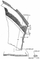
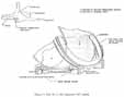
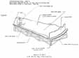
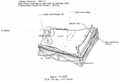
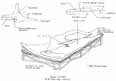
2. SRB/ET Aft Attach Ring - The SRB/ET aft attach ring is composed of a steel ring and three struts that physically attach the SRB to the ET. These attachments are designed to react to loads in place of the attach ring and allow unrestrained contraction/expansion of SRB or ET in the longitudinal direction (reference Figure 5).
The attach strut assembly provides the physical attachment between the aft ring of the SRB and the ET. The strut incorporates separation devices that release the SRB upon command (references Figures 6 and 7, and Photographs 1 and 2).
3. TVC Subsystems - The TVC, in conjunction with the SRM, provides pitch, roll, and yaw vehicle movements as desired by the Orbiter Guidance, Navigation and Control (GN&C) System. The subsystem, mounted in the aft skirt, consists of two hydraulic power units (HPU's) and two servoactuators. The two HPU's provide hydraulic power to drive the two servoactuators, designated as Rock and Tilt. These servoactuators serve to provide attitude control for each of the SRB's in response to control commands from the General Purpose Computers (GPC's) via flight control electronics in the Orbiter Vehicle (OV). (Reference Photograph 3.)
4. Separation Subsystem - The separation subsystem is designed to ensure safe separation of each of the SRB's from the ET without damaging or recontacting the Orbiter/ET during or after separation. The separation subsystem consists of a release system, sensors, and separation bolts located in the SRB/ET forward attach fitting and in each of the aft attach struts, and eight solid booster separation motors (BSM's)-four mounted in the SRB nose frustum and four mounted externally on the aft skirt. The aft motors are located unsymmetrically, which causes a small roll movement to be imparted to the SRB. The BSM's are located such that the SRB moves from the Orbiter/ET in a way that reduces the plume and particle impingement on the Orbiter. All sequencing and commands are issued by the Orbiter.
5. Recovery Subsystem - The booster recovery subsystem provides the necessary hardware to control the SRB final descent velocity and attitude after separation. The major components of the recovery subsystem are the pilot, drogue and main parachutes. The recovery subsystem includes parachutes, methods of sequencing and deploying these parachutes, parachute separation components, and location aids that help in search and retrieval operations for the expended booster and parachutes.
6. E&I Subsystem:
a. Operational System: The SRB E&I subsystem for operational flights consists of two major functional systems dedicated to two specific portions of the SRB mission. One system is operational from prelaunch until SRB/ET separation and is referred to as the Ascent System. This system consists of the E&I subsystem components necessary to respond to Orbiter vehicle (OV) commands for controlling SRB prelaunch functions, ignition, powered ascent, and SRB/ET monitored. The other system is operational from just prior to SRB/ET separation until SRB splashdown and is referred to as the Recovery System. This system consists of the E&I subsystem components that bring about the successful recovery of the SRB after burnout and separation by performing the following functions:
- 1) Severance of the nozzle extension
- 2) Deployment of the drogue and main chutes
- 3) Powering of location aids
- 4) Severance of main chute at water impact
The recovery system is simple and self-contained, except for initial POWER ON command, which is derived from the separation fire commands from the OV.
b. RSS: The RSS contains the necessary equipment to destroy the SRB in case of a malfunction requiring premature flight termination. The system is ground operated and redundant. It is monitored, tested, and safed via the Multiplexer-Demultiplexer (MDM) in the forward IEA.
III. IDENTIFICATION OF HARDWARE
Shuttle Flight 51-L SRB hardware was initially located on the ocean floor using the Klein sidescan sonar. Search patterns were established based on radar tracking of the Shuttle components. Identification of the sonar contacts was accomplished by manned and unmanned submersibles. Table 1 summarizes these submersibles.
|
SUBMERSIBLE |
TENDER SHIP |
MANNED/ UNMANNED |
|
. | ||
|
Sea Link JSL I |
Edwin Link |
Manned |
|
Sea Link JSL II |
Seward Johnson |
Manned |
|
Nuclear Sub NR-I |
Sunbird |
Manned |
|
Deep Drone |
Independence |
Unmanned |
Contractor and/or National Aeronautics and Space Administration personnel familiar with the flight hardware were on-board the manned submersibles and on-board the tender ship for the Deep Drone. The on-board personnel provided immediate identification of the hardware and pointed out specific identifying characteristics (clevis, tang, serial/part numbers, propellant thickness, inhibitor, etc.) to be recorded on video and photographed. The color video with audio and photographs made onboard the submersibles (no audio with Deep Drone) were then sent ashore for developing, duplicating, and further identification.
A. METHOD OF IDENTIFICATION.
As an aid to hardware identification, books containing photographs and illustrations of identifying characteristics were compiled and distributed to team personnel on-board recovery vessels.
The assets used to identify SRB hardware during the search operation are listed below. Identification of parts determined as....
[O246]...important for recovery by the Recovery Support personnel were prioritized and forwarded to the salvage vessels. A sketch of each piece of hardware was made to assist recovery personnel on the ships to identify attachment points. Calculated weight, center of gravity (e.g.), dimensions, and special notes concerning propellant locations or areas of caution were included.
1. Assets
- a) Underwater video tape
- b) Underwater still photographs
- c) Artist renditions of underwater artifacts
- d) Radar trajectory plots
- e) Sonar cross reference charts
- f) NASA Select Press Briefing video tape
- g) Land based photographs of recovered hardware
- h) Assembly blueprints/sketches
- i) Propellant burnback pattern charts
- j) Assembly close-out photographs
2. Identifying Characteristics
- a) Inherently unique pieces
- b) Bolt hole sizes (ET stub ring)
- c) Pin hole sizes (clevis)
- d) Proximity of known hardware (identified pieces to adjacent unidentified pieces)
- e) Pin and bolt hole locations
- f) Type of joint (factory or field, tang or clevis)
- g) Tang index slots (at 0, 118, and 240 degrees)
- h) Leak check port location (at 0 degree on tang)
- i) Insulation configuration
- j) Insulation thickness
- k) Inhibitor size and shape
- l) Propellant burnback pattern
- m) Part and serial number markings (where available)
- n) Exterior cork locations
- o) Exterior foam locations
- p) System tunnel remnants
- q) ET attach remnants
- r) Stub remnants for ET attach ring
- s) Stiffener ring remnants
- t) Case wall discoloration patterns
- u) Comparison of radar trajectory track to sonar location (latitude and longitude)
- v) Scaling known dimensions as a comparison base
- w) Paint pattern on forward skirt and frustum
- x) BSM location
Figures 8 through 12 and Photographs 4 through 13 are examples of identifying methods.
B. ANALYSIS OF VIDEO, AUDIO, AND PHOTOGRAPHS
Video, audio (where provided), and photographs of each contact were analyzed to help identify the hardware. Each video was analyzed for Shuttle element (i.e., Orbiter, SRB, Payload, etc.) by NASA and contractor representatives who were knowledgeable of hardware. These personnel provided the expertise required to assure identification of hardware that was located and filmed. Personnel who served on-board the sea vessels during the search operations also provided aid in identifying and describing the hardware. further analysis was conducted on hardware identified as part of the SRB flight element to provide data for the recovery plan. A list of hardware observed on video is listed in Appendix A.
C. HARDWARE IDENTIFIED BUT NOT RECOVERED
During the investigation, hardware of low value to the failure investigation was identified but not recovered and is listed in Table II.
Recovery plans were prepared and used as a means to obtain authorization for recovery by the Commission Task Force and to provide the requirements for recovery operations to the Salvage Team. These plans were defined based upon hardware criticality to the investigation and safety hazards (primarily to fishermen in shallow water). See Appendix B for a typical plan.
A. RECOVERY ASSETS
Assets used in the operation were owned by NASA or owned or leased by the U. S. Navy and were classified into four categories according to task assignment and capability. The categories were:
- 1) Search
- 2) Identification
- 3) Recovery
- 4) Logistics
Table III identifies each major asset used by the Task Force and includes task assignment and capabilities of each element.
|
Contact Number |
Description |
|
. | |
|
21-6 |
RH Aft Seg Stiffener |
|
21-7 |
RH Aft Seg Nozzle Part |
|
21-8 |
RH Aft Seg Nozzle Part |
|
24 |
LH Aft Seg/Dome/Kick Ring |
|
41 |
Fwd Seg/Dome/Igniter |
|
345 |
Case Fragment |
|
417 |
Case Fragment |
|
504 |
Fwd Dome/Igniter |
|
632 |
Case Fragment |
|
5125 |
Case Fragment (?) |
|
Vessel ID |
Vessel Type |
Task Assignment |
Primary Capability |
|
. | |||
|
Freedom Star |
Surface Vessel |
Search |
Side Scan Sonar |
|
Liberty Star |
Surface Vessel |
Search |
Side Scan Sonar |
|
G.W. Pierce |
Surface Vessel |
Search |
Side Scan Sonar |
|
P.L. III |
Surface Vessel |
Search |
Side Scan Sonar |
|
Seward Johnson w/Sealink II |
Surface Vessel w/manned Submersible |
Identification Recovery of small items |
Underwater Video & Photo Manned Submersible |
|
Edwin Link w/Sealink I |
Surface Vessel w/manned Submersible |
Identification Recovery of small items |
Underwater Video & Photo Manned Sumersible |
|
USS Sunbird w/NR-1 |
Surface Vessel w/manned nuclear powered Submersible |
Identification |
Long-Range Capability w/underwater Video and Photo |
|
Independence w/Deep Drone |
Surface Vessel w/Remote Operating Vehicle |
Identification |
Underwater Video |
|
USS Preserver |
Surface Vessel |
Recovery |
Dive Team to 190 Ft. |
|
Stena Workhorse w/Gemini |
Surface Vehicle w/Remote Operating Vehicle |
Recovery |
100-Ton Crane and Underwater Video |
|
LCU |
Surface Vessel |
Recovery |
Dive Team to 150 Ft. |
|
Eliminator |
Surface Vessel |
Logistics |
Logistics Support |
|
Pelican Princess |
Surface Vessel |
Logistics |
Logistics Support |
B. DEVELOPMENT OF PLAN
In order to control and provide necessary information for salvage planning, a document was prepared for each recovered part identifying:
- 1) The specific hardware to be recovered
- 2) Its location
- 3) Priority
- 4) Sea vessels to be used
- 5) Timelines
- 6) Requirements for safe handling
- 7) Critical evidence protection and preservation
- 8) Transport to shore
Individual, self-contained plans including illustrations were generated and approved by Search, Recovery and Reconstruction Team members. Figures 13 through 33 give the rationale used to determine the hardware's location and orientation on the launch vehicle assembly. Photographs 14 through 18 show the recovery operations.
C. SAFETY AND HAZARD CONSIDERATIONS
The inadvertent separation of the SRB from the ET occurred prior to the engagement of the Pyro Initiator Circuit (PIC), which controls the deployment of the various pyro devices. All ordnance devices installed on the SRB's were assumed live during retrieval operations and handled with extreme care.
The following guidelines for lifting components from the ocean were established to prevent inadvertent ignition and damage to the recovered hardware.
- 1. Avoid use of steel hooks or cables which may come in contact with suspected burn through areas.
- 2. Stabilize part prior to loading on the ship.
- 3. Tie down parts immediately after loading onto ship.
- 4. Disarm ordnance.
- 5. Neutralize forward skirt batteries (for range safety system).
- 6. Examine hydrazine tanks located in aft skirt for leakage prior to personnel entering SRB area.
The following precautions were implemented for the propellant.
- 1. Keep wet.
- 2. Do not permit shear between hard surfaces.
- 3. Do not subject to direct heat/flame.
- [O272] 4. Do not shock/drop.
- 5. Use sand bags or wood pallets to secure or brace while handling the segments of steel and propellant.
- 6. Do not place pieces of propellant in contact with each other except during and just prior to actual disposal operation.
- 7. Loose propellant should not be placed in contact with or on any case segment with propellant attached.
- 8. Store loose propellant in an approved container.
- 9. Propellant sensitivity is a function of thickness and porosity following sustained exposure to water.
- 10. Do not handle AP crystals. Insure that crystal areas are wetted down prior to movement of any propellant.
V. DESCRIPTION OF RECOVERED HARDWARE
A summary listing of all SRM hardware, including information relative to identification and location, is shown on Table IV. Due to the lack of identifying features, some parts could not be identified to the extent necessary to determine exact location on the SRB. A description of each part is provided on the following pages. Table IV summarizes the recovery hardware.
CONTACT#11 - This was the first SRB part recovered. The part was identified as a large fragment of the ET attach segment, aft segment, LH SRB. Identification was made by propellant profile analysis, hole patterns on the attach stubs, and electrical connector part numbers. The part contained both attach stubs, a tang and clevis, and a fragment of the forward stiffener segment which was attached to the tang. Approximately 80 % of the interior surface was covered with propellant. (Reference Figures 34 and 35, and Photograph 19. )
CONTACT#21-1 - This part was identified as fragments of the aft dome, aft stiffener segment, and kick ring, RH SRB. This part was identified by the part number and serial number found on the exterior surface of the part. This was a very large part and was significant in providing a base for reconstruction of the RH SRB aft segment. There was no propellant on this piece. (Reference Figure 36 and Photographs 20 and 21.)
CONTACT#21-2 - This part was identified as a RH forward stiffener segment and was identified by dimensional analysis which proved that the part matched with Contact 21-3. Contact 21-3 was positively identified as RH SRB. A factory clevis with a missing outer leg, the inactive and forward stiffener stubs, and a factory joint tang were the major design features contained on this part. There was no propellant on this part. (Reference Figure 37 and Photograph 22).
CONTACT#21-3 - This part has been identified as a fragment of the forward stiffener segment, aft segment, RH SRB. The part was identified by part number (IU50715-02) and serial number (0000002R2) found on exterior surface. Major features of this part are a clevis with the outer leg broken off and a portion of the systems tunnel. There is no propellant on the part. (Reference Figure 38 and Photograph 23.)
CONTACT#21-4 - This part has been identified as a fragment of the aft stiffener segment, aft segment, RH SRB. It was identified by the part number and serial number found on the part. Major features of the part are a field joint clevis and a stiffener ring stub. There is no propellant on the part. (Reference Figure 39 and Photograph 24.)
CONTACT#21-5 - This part is a fragment of RH aft segment, forward stiffener segment, containing the inactive stiffener stub and the active forward stiffener ring stub. The part mates with Contact 21-3 which was identified as RH SRB by a serial number. It was located laterally on the aft segment by the leak test port at 0° on the clevis. There is no propellant on this piece. (Reference Figure 40 and Photograph 25.)
CONTACT#21-9 - This part was identified as a fragment of the RH stiffener segment by part number (IU50715) and serial number (OOOOOO1R2) found on the exterior surface. The outer surface is heavily sooted except where foam residue is present. A factory clevis and factory tang are present on the piece. The piece contained no propellant. There is no evidence of heat damage on either the clevis or tang. (Reference Figure 41 and Photograph 26.)
CONTACT #26-1 - This part has been identified as the forward cylinder of the aft center segment, LH SRB. It was identified by a serial number found on the part. Major features of the part are a factory joint tang and systems tunnel floor plate fragments. The interior surface is covered with propellant. There are no apparent indications of leakage or other abnormal appearance. (Reference Figure 42 and Photograph 27.)
CONTACT #26-2 - This part was identified as a fragment of the forward cylinder, aft center segment, LH SRB. Identification was made as a result of dimensional analysis which proved that the part physically mates with Contact 26-1 at the fracture surface. Contact 26-1 was identified by serial number and part number found on the exterior surface. The interior surface of Contact 26-2 was covered with propellant. No anomalous performance features were noted on the part. (Reference Figure 43 and Photograph 28.)
CONTACT #131 - This part was identified as RH SRB aft cylinder of the aft center segment. Part number (IU50717-02) and serial number (0000060RI) were found on the exterior surface of the part. The location of the burned out area found on the part was consistent with photographic data (294 to 316). Circumferential location was determined by discovery of the 0° alignment slot on the tang. There is propellant over approximately 90 % of the surface. This part was considered a very significant finding since it is a part of the suspected burned through joint. (Reference Figures 44 through 52, and Photographs 29 through 32.)
CONTACT#195 - This part has been identified to be a section from the forward case cylinder, forward center segment, LH. The conclusion was based upon the geometry of the part which included propellant profile, plant joint tang, and field joint clevis. The tang thickness measurements were taken and favorably agreed with the manufacturing records. No anomalous performance indications were noted. (Reference Figure 53 and Photograph 33.)
CONTACT #196 - This part was identified as LH forward dome by part number (IU51473-01) and serial number (0000035) found on the part. The exterior surface is heavily sooted. No propellant was present. Insulation is present over 100% of the interior surface. (Reference Figure 54 and Photograph 34.)
CONTACT #214 - This part is a fragment of case cylinder with a factory tang and field clevis. No further identification could be made due to lack of additional identifying features. The outside surface is lightly sooted. There is propellant over approximately 60 % of the interior surface. (Reference Figure 55 and Photograph 35 )
CONTACT #292 - This part was identified as a fragment of the RH ET attach segment, aft segment. Identification was based upon comparison of the propellant profile of the part with the propellant profile on Contact #11 which is a known LH SRB attach segment part. This part was of particular interest since it contains a section from the suspect failure field joint. However, other than having a heavily-sooted appearance, no apparent indication of anomalous performance was noted. (Reference Figures 56 and 57, and Photograph 36.)
CONTACT#301 - This part was identified to be a large fragment from the aft case cylinder of the RH forward segment. Identification was made from part number and serial number found on the exterior surface. The part contains a plant joint (clevis) and field joint (tang). No anomalous performance indications were found on the hardware. (Reference Figure 58 and Photograph 37.)
CONTACT #312 - FRUSTUM SHEAR BEAM-Two fragmented pieces of frustum shear beam were recovered. These were identified by their shape and components that were attached.
|
Target |
Title |
Joint |
ID Method |
|
. | |||
|
1 |
L. H. Aft Seg, ET Attach |
Clevis Field & Tang Factory |
Propellant Profile & Connector P/N |
|
21-1 |
R. H. Aft Seg, Aft Stiffener/Aft Dome |
Clevis Factory & Tang Factory |
Part No. & Serial No |
|
21-2 |
R. H. Aft Seg, Fwd Stiffener |
Clevis Factory & Tang Factory |
Mates with 21-3 |
|
21-3 |
R. H. Aft Seg, Fwd & Aft Stiffener |
Clevis Factory |
Part No. & Serial No |
|
21-4 |
R. H. Aft Seg, Aft Stiffener |
Clevis Factory |
Part No. & Serial No |
|
21-5 |
R. H. Aft Seg-Fwd Stiff |
Clevis Factory & Tang Factory |
Mates with 21-3 |
|
21-9 |
R. H. Aft Seg, Aft Stiffener |
Clevis Factory & Tang Factory |
Part No. & Serial No |
|
26-1 |
L. H. Aft Ctr, Fwd Case Seg |
Tang Factory |
Part No. & Serial No |
|
26-2 |
L. H. Aft Ctr, Fwd Case Seg |
Clevis Field |
Mates with 26-1 |
|
131 |
R. H. Aft Ctr Seg, Aft Cylinder |
Tang Field |
Part No. & Serial No |
|
195 |
L. H. Fwd Ctr Seg, Fwd Cylinder |
Clevis Field & Tang Factory |
Tang Thickness Measurements |
|
196 |
L. H. Fwd. Seg Dome |
Tang Factory/Field |
Part No. & Serial No |
|
214 |
Ctr Seg, Fwd Cyl (Light Wt.) |
Clevis Field & Tang Factory |
Unidentifiable |
|
292 |
R. H. Aft Seg-ET Attach |
Clevis Field |
Propellant Profile- Diff to L. H. |
|
Target |
Title |
Joint |
ID Method |
|
. | |||
|
301 |
R. H. Fwd Seg, Aft Cyl. |
Clevis Factory & Tang Field |
Part No. & Serial No. |
|
325 |
R. H. Fwd Seg Aft Cyl |
Clevis Factory |
Insulation Erosion Pattern |
|
433 |
Aft Ctr Seg, Fwd Cylinder |
Clevis Field |
Inhibitor Height |
|
433-1 |
R. H. Aft Ctr Seg, Aft Cylinder |
None |
Mates with 433-2 |
|
433-2 |
R. H. Aft Ctr Seg, Aft Cylinder |
Tang Field & Clevis Factory |
Mates with 131 |
|
468 |
Fwd Seg, Aft Cyl |
Clevis Factory & Tang Field |
Propellant Burn Back Pattern |
|
487 |
Forward Skirt Clevis |
Clevis |
Holes Spaced at 1°/ Crotch Seal |
|
502 |
R. H. Fwd Ctr Seg, Aft Cyl |
Tang Field |
Part No. & Serial No. |
|
524 |
Case Cylinder |
None |
Unidentifiable |
|
538 |
R. H. Fwd Skirt |
N/A |
Paint Pattern |
|
579 |
R. H. Aft Seg, ET Attach |
Clevis Field & Tang Factory |
Part No. & Serial No. |
|
605 |
Fwd Seg, Fwd Cylinder |
Clevis Factory |
Insulation Buildup at Clevis |
|
615-3 |
R. H. Aft Seg, Aft Stiffener |
None |
Mates with 21-1 & 21-4 |
|
Target |
Title |
Joint |
ID Method |
|
. | |||
|
615-4 |
Small Piece-Case |
None |
Unidentifiable |
|
615-1A |
R. H. Fwd Ctr Seg, Fwd Cyl |
Tang Factory |
Mates with 615-2 |
|
615-1B |
R. H. Fwd Ctr Seg, Fwd Cyl |
Clevis Field |
Mates with 615-1A |
|
615-2 |
R. H. Fwd Ctr Seg, Fwd Cyl |
Clevis Field |
Part No. & Serial No |
|
631 |
Ctr Seg, Fwd Cyl |
Clevis Field & Tang Factory |
Unable to Identify L.H. or R.H. |
|
635 |
L. H. Fwd Seg Fwd Cylinder |
Clevis Factory |
Tang Thickness Measurement |
|
699 |
R. H. Fwd Ctr Seg, Aft Cylinder |
Clevis Factory & Tang Field |
Part No. & Serial No. |
|
711 |
Fwd Dome |
Fsd Skirt Clevis |
Design Features |
|
712 |
R. H. Aft Segment, ET Attach |
Tang Field |
Rework on Attach Ring |
|
5038 |
Fwd Seg, Aft Cyl |
Clevis Factory |
Propellant Burn Back Pattern |
|
5039 |
Case Cylinder |
Tang - Unknown Field/Factory |
Unidentifiable |
|
5124 |
L. H. ET/SRB Diagonal Strut |
None |
Serial Number |
|
5126-1 |
Fwd Seg, Aft Cyl |
Clevis Factory |
Propellant Burn Back Pattern |
|
5126-2 |
Fwd Seg, Aft Cyl |
None |
Wall Thickness |
|
5128 |
Fwd Seg, Case Cyl |
Tank - Unknown Field/Factory |
Wall Thickness |
[O297] CONTACT #325 - This part has been identified as an aft cylinder of a forward segment, RH. Identification was made from the insulation erosion pattern on the clevis end of the part. Also, the fracture surface mates with contact 301, which has been identified as RH by part number and serial number found on the exterior surface. There is no propellant on the part. The outside surface is moderately clean with no soot. (Reference Figure 59 and Photograph 38.)
CONTACT #433 - This part has been identified as the forward cylinder of an aft center segment (LH or RH unknown). Identification was made by inhibitor height measurement. There is no propellant on the part and the inside surface has 100% coverage of insulation and liner. (Reference Figure 60 and Photograph 39.)
CONTACT #433-1 - This part has been identified as the aft cylinder of the aft center segment, RH SRB. It mates physically at fracture surfaces with Contact 433-2 (Contact 433-2 has been positively identified as RH SRB). The inboard surface is covered 100% with insulation and approximately 50% coverage of propellant. (Reference Figure 61 and Photograph 40.)
CONTACT#433-2 - This part has been identified as an aft cylinder fragment from the aft center segment, RH SRB. The part physically mates at the fracture surface with Contact 131. Contact 131 has been identified by serial number to be RH SRB. Propellant covers approximately 70 % of the surface. (Reference Figure 62 and Photograph 41.)
CONTACT #468 - This part has been identified as an aft cylinder forward segment (LH or RH unknown). Identification was made by analysis of the propellant burn back pattern. There are no other apparent identifying features present with exception of the 118° alignment slot located on the tang. (Reference Figure 63 and Photograph 42.)
CONTACT #187 - This part has been identified as a fragment of the forward skirt clevis joint. It is made of aluminum and has the rubber crotch seal attached. No determination as to RH or LH SRB has been made. (Reference Figure 64 and Photograph 43)
CONTACT #502 - This part has been identified as a section of the aft cylinder, forward center segment, RH SRB. Identification was by serial number (0000106) and part number (IU50717-02) found on the exterior surface. There is propellant covering approximately 70% of the part. (Reference Figure 65 and Photographs 44 and 45.)
CONTACT #524 - This part has been identified as a fragment of a case cylinder segment. There is no evidence to establish whether it is RH or LH SRB. Propellant covers about 90% of the surface. (Reference Figure 66 and Photograph 46.)
CONTACT #538 - This part has been identified as the RH forward skirt with frustum separation ordnance ring and parachutes attached. It was identified by the paint pattern on the exterior surface and the serial number located on the ordnance ring. (Reference Photograph 47.)
CONTACT #538 - A part identified as a Rate Gyro assembly, RH SRB, was retrieved from the impact area adjacent to the forward skirt; therefore, the Rate Gyro and the forward skirt were assigned identical Contact Numbers. The part was identified by part number and serial number found on the identification plate.
CONTACT #579 - This part has been identified as a fragment of the attach segment, aft segment, RH SRB. Identification was made by serial number (0000006R2) found on the exterior surface. Further identification was made by inhibitor height and propellant profile analysis. The part physically mates with Contact 292 at the fracture surface. Propellant covers approximately 95 % of the interior surface. This part is considered a significant find since it is a section of the failed joint. No heat damage or other unusual conditions were noted on the part. (Reference Figure 67 and Photographs 48 and 49.)
CONTACT #605 - This part has been identified as a fragment of a forward cylinder, forward segment (LH or RH unknown). A small island of propellant was noted on the piece before recovery but was displaced and lost during the retrieval operation. There are no other apparent identifying features present. (Reference Figure 68 and Photograph 50.)
CONTACT #615-1A - This part has been identified as a fragment of forward cylinder, forward center segment, RH SRB. Identification was made by dimensional analysis which showed that the part physically mates with Contact 615-2 (615-2 was identified by serial number found on the part). This part has propellant covering approximately 80% of the interior surface. (Reference Figure 69 and Photograph 51).
CONTACT#615-1B - This part has been identified as a fragment of a forward cylinder, forward center segment, RH SRB. Identification was based on the fact that the part physically mates with Contact 615-1A at the fracture surface. Contact 615-1A has been identified as RH SRB. The interior surface of 615-18 has approximately 75% propellant coverage. (Reference Figure 70 and Photograph 52.)
CONTACT#615-2 - This part has been identified as a fragment of a forward cylinder, forward center segment, RH SRB. Identification was made by part number (IU50715) and serial number (000028R2) found on the exterior surface. The interior surface of the part has approximately 60% propellant coverage. (Reference Figure 71 and Photograph 53).
CONTACT#615-3 - This part has been identified as a fragment of the aft stiffener segment, aft segment, RH SRB. Identification was made by the fact that the part physically mates with Contacts 21-1 and 21-4 at the fracture surfaces. Contact 21-1 has been identified by serial number as RH SRB. No propellant was found on the part. (Reference Figure 72 and Photograph 54.)
CONTACT #615-4 - This part has been identified as a small fragment of a case cylinder. There are no identifying features present which can be used to obtain further definition. There is no propellant on the part. (Reference Figure 73 and Photograph 55.)
CONTACT #631 - This part has been identified as a fragment of a forward cylinder, of either a forward center or aft center segment (LH or RH unknown). Identification was made by segment length dimension, membrane wall thickness, and presence of a clevis field joint. Propellant covers approximately 75 % of the interior surface. (Reference Figure 74 and Photograph 56.)
CONTACT #635 - This part has been identified as a fragment of a forward cylinder, forward segment, LH SRB. Identification was made from tang thickness measurement which matched manufacturing records of the part. No propellant is present. (Reference Figure 75 and Photograph 40.)
CONTACT #699 - This part has been identified as a fragment of an aft cylinder, forward center segment, RH SRB. Identification was made by part number (IU50717) and serial number (0000106) found on the exterior surface. The interior surface of the part has approximately 80% propellant coverage. (Reference Figure 76 and Photograph 57.)
CONTACT #711 - This part has been identified as a fragment of a forward dome with forward skirt clevis attached. LH or RH SRB is unknown. There is no propellant on the part and no other identifying features are apparent. (Reference Figure 77 and Photograph 58.)
CONTACT #712 - This part has been identified as a part of the RH SRB attach segment of the aft segment. Identification was made by bushings found installed in the aft attach stub holes located at 268° and 209° which were traced through manufacturing records. Records indicated that bushings were used to repair holes at the exact location as found on the recovered part. Further confirmation was made by determining that the burned out area was consistent with in-flight photographic evidence (291 ° to 318°). The circumferential location was determined by relationship between unmarked alignment slot found on the tang to the unique hole pattern found on the aft attach stub. The relationship proved that the tang alignment slot was located at 240°. Approximately 80 % of the interior surface was covered with propellant. (Reference Figures 78, 79, and 80, and Photographs 59 through 62.)
[O322] CONTACT #5038 - This part was identified as a fragment of an aft cylinder, forward segment, RH or LH SRB unknown. Identification was made by propellant burn back profile analysis. No further identifying features were apparent. Approximately 70 % of the interior surface was covered with propellant. (Reference Figure 81 and Photograph 63.)
CONTACT#5039 - This part has been identified as a fragment of a case cylinder. the tang on the part cannot be identified as a factory or field joint because the insulation is missing. There is no propellant on the part. (Reference Figure 82 and Photograph 64.)
CONTACT#5124 - This part has been identified as an upper diagonal strut, LH SRB. Identification was made by serial number (2000012) found on the strut. Fragments of the external tank and SRB attach ring are attached to the ends of the strut. (Reference Figure 83 and Photograph 65.)
CONTACT#5126-1 - This part has been identified as a fragment of an aft cylinder, forward segment, RH or LH SRB unknown. No other identifying features are apparent. Approximately 60% of the interior surface is covered with propellant. Insulation is present where the propellant is missing. (Reference Figure 84 and Photograph 66.)
CONTACT#5126-2 - This part has been identified as a fragment of a case cylinder, forward segment, LH or RH SRB unknown. This fragment has no tang and no clevis. Identification was based on wall thickness measurements. No additional identifying features were apparent. There is no propellant on the part. (Reference Figure 85 and Photograph 67.)
CONTACT#5128 -This part has been identified as a fragment of a case cylinder, forward segment, LH or RH unknown. Identification was based on case wall thickness measurements. There is no propellant on the part and the majority of the internal insulation is missing. (Reference Figure 86 and Photograph 68.)
FRUSTUM - The LH and RH frustums were recovered floating on the ocean surface. The LH frustum was relatively intact with forward BSM's attached. These BSM's were later removed and are now on the EOD Range. The RH frustum was in good shape except for the missing BSM's, Contact #497, which were located on the ocean bottom.
DROGUE PARACHUTE - The LH drogue parachutes were recovered floating on the ocean surface in good condition and attached to the frustum. this part could be identified by part number and serial number on the chute.
TVC HYDRAULIC RESERVOIR - One of the two hydraulic fluid reservoirs from the RH SRB was recovered from the ocean bottom. The reservoir was still attached to a portion of the frame used to mount the unit to the aft skirt. The reservoir and frame were identified using part and serial numbers still on the hardware. Both items suffered extensive damage. This helps verify the location of the RH SRB debris.
TVC FLUID MANIFOLD - One of the two fluid manifolds in the RH SRB was recovered intact from the ocean bottom. The manifold was identified using part and serial numbers of subassemblies installed on the manifold. This helps verify the location of the RH SRB debris.
FORWARD BSM'S - The LH forward BSM's were recovered intact in the frustum. They were in excellent condition with the ignitors and nozzles present.
RATE GYRO PANEL - The LH Rate Gyro Panel was retrieved on a piece of forward skirt upper ring segment. A part number on the panel and a problem report number on the right segment aided in the identification of this hardware. There were identification plates on the gyros to aid in the identification.
AFT IEA - A fragmented section of a piece of IEA housing was found in the unidentified area of the impound room. A transducer with a part number and serial number were located on this piece. It has been verified as being the absolute pressure transducer for the LH Aft IEA.
SRB CABLE -A piece of an SRB Cable was retrieved by a shrimp boat. On the cable was a visible part number, serial, number, and reference designator of the part. It has been identified as being a RH Aft tunnel cable.
SRB CABLE - Another cable was found intact attached to a support bracket from the ETA ring. It was identified from the part number and serial number as being from the LH upper strut assembly.
ET ATTACH RING COVER AND ETHYLENE PROPYLENE DIENIE MONOMER (EPDM) STRUT COVER - An ET attach Ring cover and an EPDM Upper Strut cover were recovered from the impact area. Both items were attached to each other. The part numbers and serial numbers were clearly visible on the inside of each cover which aided in their identification.
SYSTEM TUNNEL COVER - The LH forward skirt system tunnel cover was retrieved in good condition in the impact area. It has been verified as the LH forward skirt system tunnel cover by part number and serial number.
MISCELLANEOUS - The majority of the remaining recovered SRB hardware was retrieved floating in the impact area. These included flotation foam pieces from the frustum, fragmented halves of system tunnel covers and floor assemblies, and pieces of electronic PC boards and associated attaching hardware.
Sections of forward skirt skin were recovered, two with Range Safety Antenna attached and one with an IEA support bracket base attached. The remaining sections had nothing attached. Also recovered was part of an internal forward skirt inner ring section.
VI. DISPOSITION OF RECOVERED HARDWARE
After recovery of the hardware and transportation to shore, parts were secured on wooden pallets and trucked to either Hangar "O" or the EOD Range in accordance with the "Plan for SRB Salvage Off-Load and Transport to Storage Facility," dated March 6, 1986 (see Appendix C). Due to safety concerns about the propellant remaining on some parts, access for physical analysis of the parts was restricted. After an assessment of potential means to remove propellant (i.e., water laser, hand cutting, chemical solvent, burning), the decision was made to burn the propellant at the EOD Range. Various precautions (water, putty, etc.) were used to protect the parts from further extensive damage (see propellant disposal plan in Appendix D). All parts either have had or will have the propellant removed by burning with the exception of the critical evidence, parts #131 and #712. Part #579 will be used to determine methods for a safe removal of the propellant.
All parts were extensively photographed, dimensional sketches made, and chemical samples taken prior to burning of any part to avoid potential loss of data.
Other operations, such as cutting of metallurgical samples by LSC, soot/paint sample removal, and insulation removal, have also been performed on Contact #301, to aid in the hardware analysis.
An evaluation of the use of an LSC to cut a section without propellant from a part containing propellant was conducted on part #502. The LSC failed to sever the part and resulted in igniting the propellant. This method was subsequently discontinued as a candidate to remove propellant from the critical part #131 and #712.
Currently, critical parts #131 and #712 are located in Hangar "O" with the other hardware in either the Hangar "O" area or at the EOD Range awaiting a decision on further disposition.
A. IDENTIFICATION AND RECONSTRUCTION OF RECOVERED HARDWARE
Considerable effort was expended in the identification and reconstruction of the individual pieces of recovered SRB hardware. Where possible, positive identification was made by part numbers and serial numbers found on the parts. Other identification methods employed included design features, propellant burnback analysis, paint patterns and insulation char patterns. Methods and devices used to reconstruct the individual parts included dimensional analysis of fracture patterns, design features....
[O329] ....such as forward and aft dome, stub skirts, ring stubs, alignment devices, the systems tunnel and templates. Reconstruction of the RH aft segment was accomplished by use of the templates. The templates were traced directly from each part on a flexible foam material. The traced shapes were cut from the foam sheets, rolled out flat, and placed on a dedicated floor space in Hangar AF. Each template, representing a specific part, was placed in position on the floor with respect to other parts of the pattern, resulting in the construction of a full-scale composite picture of recovered hardware. This method proved very successful in identification and placement within the SRB of previously unidentified parts and provided information relative to shape, size, and location of missing parts. Reference Photograph 69.
B. PERCENTAGE OF RECOVERED SRM HARDWARE
Percentage of the recovered SRM hardware has been estimated by comparing the surface area of the fragments recovered to the actual surface area of the SRM's. The forward skirt, aft skirt, forward exit cone and aft exit cone were not included in the calculations. The results are shown on Table V (reference Figures 87 and 88).
|
Total SRM Surface Area | ||
|---|---|---|
|
. | ||
|
Forward Segment |
-168,244 in2 | |
|
Forward Center Segment |
-150,444 in2 | |
|
Aft Center Segment |
-150,444 in2 | |
|
Aft Segment |
-182,497 in2 | |
|
. |
|
651,629 in2 |
|
. | ||
|
Recovered Hardware |
Approximate In2 |
Approximate % of Total for One SRM |
|
. | ||
|
Right-Hand SRM Surface Area |
|
|
|
Left-Hand SRM Surface Area |
|
|
|
Unknown SRM Surface Area |
|
|
|
. | ||
|
. |
Approximate In2 |
Approximate % of Total for One SRM |
|
. | ||
|
Total Recovered SRM Surface Area |
|
|
C. PROPELLANT DISPOSAL OPERATIONS.
Propellant remaining on the insulation and steel case fragments and bulk propellant with the exception of parts #131, #712, and #579 was disposed of by procedures approved by applicable Search, Recovery and Reconstruction Team members. (Reference Appendix D for the original disposal plan and Photographs 70, 71, and 72 for disposal configuration.)
Reviews of the visual data (film/video) of the STS 51-L mission indicated a flame source in the area of Station 1491.48 field joint at approximately the 300° circumferential location on the RH SRB. Two pieces of hardware were recovered and analyzed to confirm the source location of the failure. The part located at Sonar Contact #131 was determined by part number and serial number found on the case wall to be part of the RH SRB aft center segment. The tang end, which mates with the aft segment ET attach segment, was found to contain a burned area in the circumferential location from 294° to 316°. Another part located at Sonar Contact #712 was determined by a comparison of the part's features as documented in manufacturing records and the recovered hardware to be a piece of the RH aft segment ET attach segment. It also contained a burned-out area in the circumferential location of 291° to 318°. After examination by personnel from MSFC, JSC, NTSB, and others, it has been concluded that the source of the flame seen in the STS 51-L visual records was in the area of the RH aft center to aft segments field joint in the 291° to 318° circumferential location. Findings from a detailed examination and analysis of the parts is published in a separate report.
Other SRB parts recovered were examined for evidence of abnormal flight operation but none were noted. However, it should be stated that the condition of the hardware caused by the explosion, range destruct, water impact, subsequent impact with the ocean bottom, exposure to the ocean environment for almost three months, and subsequent recovery operations resulted in a major inability to assess anomalous flight conditions. A combustion gas blowby at the joint O-rings is normally determined by examination of the O-rings for erosion or sooting and of the O-ring grooves and lands for soot deposits or burned grease. No O-rings from the 51-L SRB joints were found and, due to the environments that the metal experienced, evidence of blowby on the grooves could have easily been removed.
In conclusion, it is believed that the Search and Recovery operation to find evidence to confirm the flame source location was highly successful, but the recovered hardware is of minor value relative to cause of the failure at the joint.
|
POSITION |
DESCRIPTION |
|
|
|
. | |||
|
** TAPE NUMBER: 008 | |||
|
. | |||
|
* SOURCE OF TAPE : 2-15-86:P+T 8FR & 2-16-86:5R8 Segment, Deep Drone #1 | |||
|
665-END |
LH AFT SECTION WITH ETA RING |
SRB |
. |
|
. | |||
|
** TAPE NUMBER: 010 | |||
|
. | |||
|
* SOURCE OF TAPE : Fixed Camera with Deep Drone #1 | |||
|
868-890 |
LOOKS LIKE A SEGMENT, VISIBILITY VERY POOR |
SRB |
. |
|
. | |||
|
** TAPE NUMBER: 011 | |||
|
. | |||
|
* SOURCE OF TAPE : Fixed Camera with Deep Drone #2 | |||
|
ALL |
COMPLETELY OUT OF FOCUS |
SRB |
. |
|
. | |||
|
** TAPE NUMBER: 012 | |||
|
. | |||
|
* SOURCE OF TAPE : JOHNSON SEALINK II, DIVE #1244, TAPE 1. | |||
|
266 |
INSIDE AFT SKIRT,PART OF KICK RING |
SRB |
0 |
|
282 |
NOZZLE, BLAST SHIELD FOR LSC (UPSIDE DN) |
SRB |
0 |
|
324 |
BSM, ANOTHER VIEW |
SRB |
0 |
|
380 |
AFT STRU, END OF AFT SKRT INT.COSTAL RIB |
SRB |
0 |
|
430 |
FWD NOZZLE EXIT CONE STRU. HOUSING |
SRB |
0 |
|
. | |||
|
* SOURCE OF TAPE : JOHNSON SEALINK II, DIVE #1244, TAPE 2 | |||
|
. | |||
|
123 |
AFT SKIRT STRU. EXT. VIEW LOOKING INWARDS TO TVC |
SRB |
0 |
|
142 |
STRUCTURE ? (BRKT) |
SRB |
0 |
|
171 |
STRUCTURE ? |
SRB |
0 |
|
198 |
TVC SYST BKT |
SRB |
0 |
|
214 |
TVC MANIFOLD |
SRB |
0 |
|
228 |
AFT SKRT, T-RING, FASTENERS, GUSSETS, CLIPS, POS. SRB FUEL ISO VALVE |
SRB |
0 |
|
314 |
BOTTOM OF AFT SKIRT |
SRB |
0 |
|
450-470 |
POSSIBLE AFT DOME, SEE GLASS WRAP |
SRB |
0 |
|
. | |||
|
* SOURCE OF TAPE : JOHNSON SEALINK II, DIVE #1244, TAPE 3 | |||
|
034-038 |
STRUTURAL MEMBER, NOZZLE FIXED HOUSING, GUIDE PIN BOLT HOLES |
SRB |
0 |
|
118 |
FUEL ISO VALVE ATTACH STRUCTURE |
SRB |
0 |
|
186 |
CYLINDER SECTION OF SRM |
SRB |
0 |
|
282 |
SECTION OF KICK RING |
SRB |
0 |
|
365 |
AFT SKIRT WITH BSM |
SRB |
0 |
|
434 |
AFT SKIRT STRUCTURE - AFT ATTACH RSM |
SRB |
0 |
|
* SOURCE OF TAPE : JOHNSON SEALINK II, DIVE #1244, TAPE | |||
|
018 |
ACTUATOR ATTACH BRACKET - AFT SKIRT |
SRB |
0 |
|
060 |
TUNNEL FLOOR PLATE AND ROOSTER TAIL |
SRB |
0 |
|
087-090 |
PHENOLIC |
SRB |
0 |
|
102 |
ALUMINIM SKIN - AFT SKIRT |
SRB |
0 |
|
142 |
AFT SEGMENT STIFFENER "T" RING |
SRB |
0 |
|
177 |
PIN RETAINER BAND |
SRB |
0 |
|
199 & 218 |
NOZZLE GLASS PHENOLIC |
SRB |
0 |
|
243 |
STIFFENER RING |
SRB |
0 |
|
244 |
NOZZLE GLASS PHENOLIC |
SRB |
0 |
|
256 |
AFT STRUCTURE STIFFENER |
SRB |
0 |
|
263 |
GLASS PHENOLIC KING & UNIDENTIFIED AL. STRUCTURE BRACKET |
SRB |
0 |
|
271 |
NOZZLE GLASS PHENOLIC |
SRB |
0 |
|
290 |
SHORT SECTION TUNNEL COVER |
SRB |
0 |
|
311 |
NOZZLE THROAT CARB0N PHENOLIC KING |
SRB |
0 |
|
325 |
PHENOLIC GLASS |
SRB |
0 |
|
352 |
PHENOLIC GLASS AND CARB0N RING AREA |
SRB |
0 |
|
374 |
PHENOLIC GLASS |
SRB |
0 |
|
398 |
CARB0N PHENOLIC RING AND RECTANGULAR PLATE ? |
SRB |
0 |
|
412 |
ALUMINUM SHEET FHAGMENT |
SRB |
0 |
|
417 |
PHENOLIC GLASS |
SRB |
0 |
|
431 |
AFT INTEHNAL RING FRAGMENT ? |
SRB |
0 |
|
455 |
PHENOLIC GLASS |
SRB |
0 |
[O333] UNDERWATER VIDEO LOG
|
POSITION |
DESCRIPTION |
|
|
|
. | |||
|
**TAPE NUMBER: 016 | |||
|
. | |||
|
030 |
AFT SECTION WITH INSTAFOAM (SMALL) |
SRB |
0 |
|
070-090 |
PHENOLIC GLASS |
SRB |
0 |
|
125 |
KICK RING PHENOLIC COVER |
SRB |
0 |
|
181 |
CARB0N PHENOLIC NOZZLE |
SRB |
0 |
|
189 |
LINEAR SHAPE CHARGE (NOZZLE SEVERANCE) |
SRB |
0 |
|
201-202 |
PHENOLIC GLASS |
SRB |
0 |
|
. | |||
|
**TAPE NUMBER: 017 | |||
|
. | |||
|
* SOURCE OF TAPE : JOHNSON SEALINK II, DIVE #1245, TAPE 1 | |||
|
061-410 |
ALL VIEWS OF SEGMENT ARE EXTERIOR |
SRB |
0 |
|
294 |
PIN RETAINER BAND |
SRB |
0 |
|
300 |
KICK RING |
SRB |
0 |
|
366 |
AFT SKRT & SEGMENT (KICK RING, AFT CLOSURE, AFT STIFFENER SEG) |
SRB |
0 |
|
423 |
FWD EXIT CONE NOUSING, EXT VERY SOOTED, STRU DAMAGE TO JOINT |
SRB |
0 |
|
. | |||
|
**TAPE NUMBER: 018 | |||
|
. | |||
|
* SOURCE OF TAPE : JOHNSON SEALINK II, DIVE #1245, TAPE 2 | |||
|
022 |
AFT SKIRT FRAGMENTS |
SRB |
0 |
|
076 |
SMALL AFT SKIRT FRAGMENTS |
SRB |
0 |
|
089 |
TVC APU SYSTEM WITH HYDRAULIC PUMP |
SRB |
0 |
|
119-180 |
SUB OPERATOR DESCRIBED 0BJECT AS PART OF EXIT CONE |
SRB |
0 |
|
251 |
AFT SKIRT RING AND SKIN FRAGMENT |
SRB |
0 |
|
346 |
GLASS PHENOLIC |
SRB |
0 |
|
359 |
SECTION OF AFT SKIRT |
SRB |
0 |
|
365 |
AFT SKIRT AFT RING FRAGMENT |
SRB |
0 |
|
374 |
POSSIBLE NOZZLE SNUBBER |
SRB |
0 |
|
414 |
FWD EXIT CONE HOUSING |
SRB |
0 |
|
448 |
AFT SKIRT SEGMENT |
SRB |
0 |
|
458 |
PART OF UPPER TVC FRAME AND HYDRAULIC RESERVOIR |
SRB |
0 |
|
** TAPE NUMBER: 019 | |||
|
. | |||
|
* SOURCE OF TAPE : JOHNSON SEALINK II, DIVE #1246, TAPE 1 | |||
|
016 |
SMALL UNIDENTIFIED FRAGMENT |
SRB |
0 |
|
044 |
ELECTRICAL CABLE |
SRB |
0 |
|
062 |
INTERNAL PLATES OF HDP |
SRB |
0 |
|
082 |
AFT SKRT STRUC.,SECTION OF MID-RING FOAM & SKIN PNL,4 x 4 ft |
SRB |
0 |
|
143 & 166 |
AFT SKIRT FRAGMENT |
SRB |
0 |
|
164 |
FEED THRU ASSEMBLIES (ROOSTER TAIL & TUNNEL FLOOR) |
SRB |
0 |
|
182 |
AFT SKIRT FRAGMENT |
SRB |
0 |
|
190 |
ALUMINUM FRAGMENT |
SRB |
0 |
|
208 |
CASE SEGMENT STIFFENER RING WITH SPLICE JOINT |
SRB |
0 |
|
217 |
LOWER TVC FRAME SECTION & HYDRAULIC RESERVOIR CLAMP |
SRB |
0 |
|
236-284 |
CASE SEGMENT SHOWING TANG WITH TANG SLOT |
SRB |
0 |
|
316-338 |
AFT SKRT STRUC. TRAILING EDGE (3x12 ft) & WHALEBONE |
SRB |
0 |
|
394 |
AFT SKIRT FRAGMENT |
SRB |
0 |
|
409 |
AFT SKIRT FRAGMENT WITH CORK AND RING SHIMS |
SRB |
0 |
|
439 |
NOZZLE CARBON PHENOLIC - INTACT |
SRB |
0 |
|
456 |
UNIDENTIFIED NOZZLE RING WITH FLAP |
SRB |
0 |
|
478 |
CLEVIS RING JOINT - POSSI8LE D-RING GROOVE |
SRB |
0 |
|
. | |||
|
**TAPE NUMBER : 022 | |||
|
. | |||
|
* SOURCE OF TAPE : DEEP DRONE PAN & TILT PART 1 | |||
|
596 |
PN #127527-1?? |
SRB |
0 |
|
. | |||
|
**TAPE NUMBER: 023 | |||
|
. | |||
|
* SOURCE OF TAPE : DEEP DRONE PAN & TILT PART 2 | |||
|
0-160 |
THIN SKINNED STRUCTURE WITH RIBS |
SRB |
0 |
|
. | |||
|
**TAPE NUMBER :028 | |||
|
. | |||
|
* SOURCE OF TAPE : DEEP DRONE PAN & TILT TAPE 1 | |||
|
009-535 |
AFT SKIRT |
SRB |
0 |
|
535-END |
FORWARD SKIRT |
SRB |
0 |
|
. | |||
|
**TAPE NUMBER: 029 | |||
|
. | |||
|
* SOURCE OF TAPE : DEEP DRONE PAN & TILT TAPE 2 | |||
|
001-510 |
FWD SKIRT |
SRB |
0 |
|
510-609 |
CANNOT IDENTIFY A RING WITH A SPRING ON END. 1 1/2 DIA 3 TO 4 INCHES LONG |
SRB |
0 |
|
609-END |
SCATTERED DEBRI, THERMAL CURTAINS, THERMAL CURTAIN RETAINERSWHALE B0NE, AFT SKIRT RIBS WITH SOME SKIN, BLACK B0X AFT SKIRT STIFFENERS OR FWD?? |
SRB |
0 |
[O334] UNDERWATER VIDEO LOG
|
POSITION |
DESCRIPTION |
ORBITER SYSTEM |
TARGET NUMBER |
|
. | |||
|
** TAPE NUMBER : 030 | |||
|
. | |||
|
* SOURCE OF TAPE : JOHNSON SEALINK II, DIVE #1247 | |||
|
020 |
TVC FRAME & TUBING WITH FLEXHOSE |
SRB |
0 |
|
051 |
STIFFENER RING - 90 DEGREES TUNNEL SPLICE AREA |
SRB |
0 |
|
071 |
GLASS PHENOLIC - NOZZLE |
SRB |
0 |
|
102 |
GLASS PHENOLIC - SKIRT PARTS |
SRB |
0 |
|
138 |
GLASS & CARB0N PHENOLIC - NOZZLE |
SRB |
0 |
|
167 |
SYSTEMS TUNNEL - BOTTOM UP - AFT POOSTER (WITH COVER) |
SRB |
0 |
|
191 |
EXHAUST DUCT OH TVC TUBING |
SRB |
0 |
|
204 |
GLASS PHENOLIC |
SRB |
0 |
|
235 |
STIFFENER RING - 90 DEGREES TUNNEL SPLICE ARES |
SRB |
0 |
|
320 |
NOZZLE RING CARBON |
SRB |
0 |
|
340 |
AFT SKIRT SKIN |
SRB |
0 |
|
366 |
CARBON PHENOLIC - NOZZLE |
SRB |
0 |
|
385 |
SMALL FRAGMENT |
SRB |
0 |
|
396 |
PHENOLIC, SMALL PIECE |
SRB |
0 |
|
406 |
AFT SKIRT FRAGMENT |
SRB |
0 |
|
415 |
AFT SKIRT FRAGMENT |
SRB |
0 |
|
423 |
AFT SKIRT SKIN |
SRB |
0 |
|
436 |
UNIDENTIFIED RING |
SRB |
0 |
|
442 |
CAR80N PHENOLIC |
SRB |
0 |
|
. | |||
|
TAPE NUMBER : 031 | |||
|
. | |||
|
* SOURCE OF TAPE : JOHNSON SEALINK II, DIVE #1248, TAPE 1 | |||
|
013 |
PIN RETAINER BAND |
SRB |
0 |
|
116 |
CARBON L GLASS PHENOLIC - NOZZLE |
SRB |
0 |
|
177 |
CARBON PHENOLIC |
SRB |
0 |
|
187 |
GLASS PHENOLIC |
SRB |
0 |
|
218 |
CARBON PRENOLIC |
SRB |
0 |
|
264 |
LSC SILICONE RETAINER - NO CHANGE |
SRB |
0 |
|
293 |
TVC BRACKET |
SRB |
0 |
|
325 |
PIECE OF CURTAIN WITH RIVET HOLES, GLASS PHENOLIC |
SRB |
0 |
|
374 |
SKIN FRAGMENT |
SRB |
0 |
|
385 |
GLASS PKENOLIC |
SRB |
0 |
|
394 |
SKIN THERMAL CURTAIN |
SRB |
0 |
|
409 |
GLASS PHENOLIC |
SRB |
0 |
|
427 |
GLASS PHENOLIC |
SRB |
0 |
|
438 |
CARBON PHENOLIC |
SRB |
0 |
|
455 |
SKIRT FRAGMENT |
SRB |
0 |
|
. | |||
|
** TAPE NUMBER: 032 | |||
|
. | |||
|
* SOURCE OF TAPE : JOHNSON SEALINK II, DIVE #1248, TAPE 2 | |||
|
011 |
GLASS PHENOLIC |
SRB |
0 |
|
145 |
NOZZLE, 3 FT SQUARE |
SRB |
. |
|
228 |
NOZZLE RING, APPROX. 30 |
SRB |
. |
|
315 |
NOZZLE (YELLOW) |
SRB |
. |
|
402 |
NOZZLE (YELLOW BAND) |
SRB |
. |
|
. | |||
|
* SOURCE OF TAPE : JOHNSON SEALINK II, DIVE #1249 | |||
|
025 |
RH AFT BOOSTER ON SKIRT |
SRB |
. |
|
055 |
SKIN TUNNEL AREA PROPELLANT |
SRB |
. |
|
160 |
SKIN OF SEGMENT W/SYSTEMS TUNNEL AT STIFFENER RING |
SRB |
. |
|
. | |||
|
** TAPE NUMBER : 034 | |||
|
. | |||
|
* SOURCE OF TAPE : DEEP DRONE PAN & TILT, 2-16-86 - 2-19-86 | |||
|
001 |
AFT BOOSTER |
SRB |
. |
|
060 |
AFT BOOSTER, ETA RING (LH) PARTIAL |
SRB |
. |
|
ALL |
PROBABLE PART OF LH SRM AFT SEGMENT |
SRM |
0 |
|
ALL |
CIRC. SECTION OF SRM ET ATTACH RING SEGMENT |
SRM |
0 |
|
ALL |
LENGTH FROM FWD FIELD JOINT TO FWD STIFFENER |
SRM |
0 |
|
ALL |
SEGMENT SURFACE DOES NOT APPEAR TO BE SOOTED |
SRM |
0 |
|
ALL |
INHIBITOR STUB REMAINING APPEAR NORMAL OVER 180 CIRC. |
SRM |
0 |
|
ALL |
NO PROPELLANT WAS NOTED |
SRM |
0 |
|
ALL |
ET ATTACH RING AFT JOINT HAS HOLES EXPOSED |
SRM |
0 |
|
. | |||
|
* SOURCE OF TAPE : DEEP DRONE FIXED 2-16-86 - 2-19-86 | |||
|
200-END |
LH AFT BOOSTER ETA RING SECTION, POOR SRB VISIBILITY |
SRB |
. |
|
. | |||
|
* SOURCE OF TAPE : JOHNSON SEALINK II, DIVE #1250 OOC TARGET 26 | |||
|
. |
SRB SEGMENT CASE W/PROPELLANT SRB |
SRB |
. |
|
120 |
LT WT CASE ;US0717-02, S/N #0000075R1, SRB FACTORY JOINT TANG |
SRB |
. |
|
300-END |
SEGMENT CASE W/PROPELLANT FIELD JOINT SRB CLEVIS |
SRB |
. |
[O335] UNDERWATER VIDEO LOG
|
POSITION |
DESCRIPTION |
ORBITER SYSTEM |
TARGET NUMBER |
|
. | |||
|
** TAPE NUMBER: 037 | |||
|
. | |||
|
* SOURCE OF TAPE : JOHNSON SEALINK II, DIVE #1250 OOC #26 TARGET 182 | |||
|
001-296 |
SRM CASE PIECE S.N. 0000075R1, PART # 1050717-02 WITH TANG PROPELLANT ABOUT 1.5"-2" THICK, DEPTH - 234 FT |
SRB |
182 |
|
1-296 |
SRM CASE PIECE S.N. 0000075R1 PART #1050717-02 WITH TANG PRO |
SRM |
0 |
|
296 |
SRM CASE PIECE INHIB!TOR AT JOINT & PROPELLANT GRAIN 2 |
SRM |
0 |
|
. | |||
|
* SOURCE OF TAPE : JOHNSON SEALINK II: DIVE #1250 OOC #26 TARGET 182 | |||
|
296-END |
SRM CASE PIECE INHIBITER AT JOINT + PROPELLANT GRAIN APPOX. 2" THICK. SHOWS SHAPE CHARGE CUT? CLEVIS END OUTER LEG BROKEN AWAY, 4.5 - 5 FT ARC, LENGTH - 8 FT, DEPTH -234 FT |
SRB |
182 |
|
. | |||
|
* SOURCE OF TAPE : JOHNSON SEALINK II, DIVE #1250 OOC #26 TARGET 182 | |||
|
315 |
PIECE OF LH SRM STEEL SEGMENT - 8 FT LONG X 4-5 FT CIRCUM CLEVIS END OF FIELD JOINT SHOWING WITH INHIBITOR FLAP ALSO SOME CHROMATE PUTTY VISIBLE. PROPELLANT VISIBLE. |
SRB |
. |
|
315 |
BASED ON HEIGHT OF INHIBITOR, PART APPEARS TO BE ALSO AFT CENTER SEGMENT |
SRB |
. |
|
470 |
FWD CASE SEGMENT |
SRB |
. |
|
8 |
LARGE PIECE OF LH SRM, AFT CTR FWD CASE SEGMENT STEEL SEGMENT - 10 FT LONG X 7-8 FT CIRCUM, IDENT S/N 075rl 2" OF PROPELLANT VISIBLE ON CASE WALL |
SRB |
. |
|
. | |||
|
** TAPE NUMBER : 041 | |||
|
. | |||
|
* SOURCE OF TAPE : JOHNSON SEALINK II, DIVE #1257, OOC #41 (J5-1) | |||
|
250 |
IGNITER |
SRM |
0 |
|
ALL |
SRM DOME, IGNITER & FWD SKIRT SKIN & CLEVIS TANG 180 |
SRM |
0 |
|
ALL |
SRM DOME, IGNITER, & FWD SKIRT |
SRB |
. |
|
. | |||
|
** TAPE NUMBER : 042 | |||
|
. | |||
|
* SOURCE OF TAPE : JOHNSON SEALINK II,DIVE #1257,00C #41 (CONTINUATION) (J5-2) | |||
|
190 |
FORWARD SKIRT AFT CLEVIS TANG |
SRM |
0 |
|
198 |
FORWARD DOME WITH IGNITER |
SRM |
0 |
|
200 |
IGNITER |
SRM |
0 |
|
ALL |
SRM DOME, IGNITER & FWD SKIRT SKIN & CLEVIS TANG 180 |
SRM |
0 |
|
ALL |
SRM DOME,IGNITER & FWD SKIRT |
SRB |
. |
|
. | |||
|
** TAPE NUMBER : 044 | |||
|
. | |||
|
* SOURCE OF TAPE : DEEP DRONE FIXED TARGET 2 & 37, 2 OF 6 | |||
|
. |
SCATTERED DEBRI? VERY POOR VISABILITY |
SRB |
. |
|
. | |||
|
** TAPE NUMBER : 049 | |||
|
. | |||
|
* SOURCE OF TAPE : NR-1, TAPE #5 (DUPLICATE OF TAPE #057) | |||
|
1789-1830 |
CONTACT 17 FROM PREVIOUS TAPE, HYDRAZINE BOTTLE |
SRB |
0 |
|
2100-3400 |
CONTACT #1 FROM PREVIOUS TAPE - AFT 1/3 OF SRB AFT MOTOR CASE OR AFT SKIRT SEGMENT RIGHT @ 10:28 |
SRB |
0 |
|
4300 |
4 x 4 FT PIECE OF SRM SKIN W/TUNNEL, POSS. PART OF 3RD STIFFNER RING BLACKENED 1285 DEPTH POSS. W/FACTORY JOINT IN MIDDLE, MID & UPPER STIFFENER RING PIECES, CABLES IN TUNNEL SECTION |
SRB |
0 |
|
4950-END |
CABLE, CONTACT 94, POSSIBLY WITH STRAP, TIME 14:02 HOURS |
SRB |
0 |
|
. | |||
|
** TAPE NUMBER : 053 | |||
|
. | |||
|
* SOURCE OF TAPE : NR-1, TAPE #1, ID #001, AREA A | |||
|
0500-2220 |
CONTACT #1, 28 49 14 N, 79 52 39 W, AFT SEGMENT SITTING ON AFT SKIRT |
SRB |
. |
|
2872 |
3 STIFFENER RINGS 41 CLEVIS - SPREAD OPEN JOINTS BROKEN |
SRB |
. |
|
2872 |
APPEARS TO BE INSIDE OF SKIRT |
SRB |
. |
|
2872 |
PAT COMMENT. WOULD PROBABLY BREAK UP WHEN LIFTED |
SRB |
. |
|
4706 |
NOZZLE THROAT. LOOKING DOWN 12-15 FT ACROSS X SRB 6-7 FT OFF SURFACE |
SRB |
. |
|
5580 |
BOOSTER SEPARATION MOTOR ON PIECE OF AFT SRB SKIRT |
SRB |
. |
|
ALL |
RH AFT BOOSTER (PORTION) AND SCATTERED DEBRI |
SRB |
. |
[O336] UNDERWATER VIDEO LOG
|
POSITION |
DESCRIPTION |
ORBITER SYSTEM |
TARGET NUMBER |
|
. | |||
|
** TAPE NUMBER: 054 | |||
|
. | |||
|
* SOURCE OF TAPE : NR-1, TAPE #2, ID #001, AREA A | |||
|
0000-0140 |
FORWARD FIXED HOUSING (NOZZLE) CONTACT #8 |
SRB |
. |
|
1150 |
CONTACT #10, AFT BOOSTER |
SRB |
. |
|
1328 |
CONTACT 11 |
SRB |
. |
|
. | |||
|
** TAPE NUMBER: 056 | |||
|
. | |||
|
* SOURCE OF TAPE : NR-1, TAPE #4, ID #001, AREA A | |||
|
20 |
PIECES OF NOZZLE |
SRB |
. |
|
ALL |
VARIOUS SCATTERED DEBRI, NOZZLE |
SRB |
. |
|
. | |||
|
** TAPE NUMBER: 057 | |||
|
. | |||
|
* SOURCE OF TAPE : NR-1, TAPE #5, ID #001, AREA A | |||
|
ALL |
SCATTERED DEBRIS, NOZZLE |
SRB |
. |
|
. | |||
|
** TAPE NUMBER: 058 | |||
|
. | |||
|
* SOURCE OF TAPE : NR-1, TAPE #6, ID #001, AREA A | |||
|
1250-1405 |
AFT SKIRT, ACTUATOR ROD BURIED IN SAND, ACTUATOR STIFFENER IN SKIRT |
SRB |
. |
|
2660 |
BUNDLE OF RINGS?? NOT CLEAR |
SRB |
. |
|
. | |||
|
** TAPE NUMBER : 059 | |||
|
. | |||
|
* SOURCE OF TAPE : NR-1, TAPE #7, ID #001, AREA A | |||
|
2245 |
HYDRAZINE TANK |
SRB |
. |
|
2270 |
HYDRAZINE BOTTLE 8' LONG OBJECT |
SRB |
. |
|
2395 |
HYDRAULIC RESERVOIR |
SRB |
. |
|
2479 |
RUTURED VIEW OF HYDRAZINE TANK |
SRB |
. |
|
2580 |
HYDRAZINE BOTTLE (RUPTURED; WITH HYDRAULIC ACTUATOR |
SRB |
. |
|
2585 |
VIEW OF TVC FRAME AND HYDRAULIC RESERVOIR |
SRB |
. |
|
2639 |
VIEW OF HYDRAULIC RESERVOIR (CLOSE UP) |
SRB |
. |
|
2660 |
TVC LOWER FRAME (CLOSE UP) |
SRB |
. |
|
2880 |
HYDRAULIC ACTUATOR |
SRB |
. |
|
2959 |
NOZZLE PART CONTACT #148 |
SRB |
. |
|
3060 |
SKIN 3' X 8' SEGMENT CONTACT #149 |
SRB |
. |
|
3185 |
NOZZLE PART 5' DIA 200 COMPLETE |
SRB |
. |
|
3300 |
3' X 8' SKIN |
SRB |
. |
|
3370 |
AFT SKIRT SKIN WITH CABLES AND COMPONENT IDENTIFIED AS ACTUATOR |
SRB |
. |
|
3496 |
PILE OF DEBRIS ACTUATOR |
SRB |
. |
|
4030 |
LARGE MASS OF METAL ACTUATOR |
SRB |
. |
|
4390 |
ACTUATOR? |
SRB |
. |
|
4540 |
ACTUATOR |
SRB |
. |
|
4613 |
120 NOZZLE PART, HEAVY PIECE LEFT CRATER IN SAND |
SRB |
. |
|
4766 |
NOZZLE PART |
SRB |
. |
|
4910 |
RING |
SRB |
. |
|
4990 |
2' x 4' FPIECE |
SRB |
. |
|
5085 |
I BEAM TYPE MATERIAL |
SRB |
. |
|
5125 |
PORTION OF SKIRT |
SRB |
. |
|
5235 |
SKIN PIECE FOLDED DIA APPROX 4' |
SRB |
. |
|
5238 |
NOZZLE PART 360 INTACT AROUND |
SRB |
. |
|
5250 |
CIRCULAR PIECE 270 INTACT (NOZZLE RING) |
SRB |
. |
|
5325 |
8' LONG SKIN |
SRB |
. |
|
5335 |
10' X 6' PARTIALLY COVERED WITH SAND |
SRB |
. |
|
5590 |
15' LONG NOZZLE PIECE COMPLETE 180 |
SRB |
. |
|
**TAPE NUMBER : 060 | |||
|
. | |||
|
* SOURCE OF TAPE: NR-1, TAPE #8, ID #001, AREA A | |||
|
0130 |
3' x 4' AFT SKIRT |
SRB |
. |
|
0487 |
3' x 4' AFT SKIRT |
SRB |
. |
|
1637 |
MOTOR SKIN & CONTINUED FROM TAPE POSITION 1637 TILL 2295 |
SRB |
. |
|
2212 |
PORTION OF A RING SIGHTED AND "IN" CLIPS |
SRB |
. |
|
2615 |
12' x 8' SRB SKIN STIFFENER RING WAS LOCATED IN THE AREA BY WHITE LINE. SURFACE OF SKIN APPEARS CHARRED |
SRB |
. |
|
2920 |
NOZZLE PARTS, COMPLIANCE RING |
SRB |
. |
|
3730 |
WHALE BONE, SNUBBER |
SRB |
. |
|
3940 |
1' LONG 6" WIDE |
SRB |
. |
|
4120 |
6' DIAMETER CARBON MATERIAL FROM NOZZLE |
SRB |
. |
|
4320 |
NOZZLE PIECE |
SRB |
. |
|
5021 |
4' WIDE 20' IN LENGTH NOZZLE MATERIAL |
SRB |
. |
|
5143 |
COMPLETE 360 FANALIC MATERIAL |
SRB |
. |
[O337] UNDERWATER VIDEO LOG
|
POSITION |
DESCRIPTION |
ORBITER SYSTEM |
TARGET NUMBER |
|
. | |||
|
** TAPE NUMBER: 061 | |||
|
. | |||
|
* SOURCE OF TAPE: NR-1, TAPE #9, ID #001, AREA A | |||
|
0330 |
AFT SKIRT PIECE |
SRB |
. |
|
0699 |
I BEAM FROM BULKHEAD |
SRB |
. |
|
0945 |
RING COMPLETE NOZZLE MATERIAL |
SRB |
. |
|
1035 |
HYDRAZINE BOTTLE, PREVIOUSLY SEEN |
SRB |
. |
|
1494 |
DEBRI |
SRB |
. |
|
1690 |
CRUMPLED INSULATION MATERIAL |
SRB |
. |
|
2045 |
SKIRT WITH CONTROLS |
SRB |
. |
|
2050 |
BOOSTER SNUBBER, TWISTED METAL |
SRB |
. |
|
2360 |
TEN FEET LONG |
SRB |
. |
|
2777 |
NOZZLE RING |
SRB |
. |
|
3256 |
SEGMENT SKIN, APPEARED CHARRED |
SRB |
. |
|
3600 |
PIECE OF MATERIAL 5' WIDE 4' LONG |
SRB |
. |
|
3600 |
PIECE OF I BEAM |
SRB |
. |
|
3895 |
10' PIECE |
SRB |
. |
|
4460 |
PIECE OF PIPE AND 2 FT SQ PIECE OF MATERIAL |
SRB |
. |
|
4550 |
TWO PIECES OF NOZZLE MATERIAL |
SRB |
. |
|
. | |||
|
** TAPE NUMBER: 062 | |||
|
. | |||
|
* SOURCE OF TAPE: NR-1, TAPE #10, ID #001, AREA A | |||
|
1005 |
CONTACT 268 190 RING MAT'L NOZZLE |
SRB |
. |
|
1760 |
CONTACT 271, BLACK RING NOT IN VIEW |
SRB |
. |
|
3003 |
CONTACT 281 SKIN MATERIAL 2' x 3' |
SRB |
. |
|
4451 |
CONTACT 287 RING DIA 5' TO 6' |
SRB |
. |
|
4700 |
CONTACT 290 10' x 10' SKIN MATERIAL, POSSIBLE ONE OF FWD SEGMENTS TANG JOIN |
SRB |
. |
|
5438 |
LOST VISUAL CONTACT MAINTAINED AUDIO |
SRB |
. |
|
. | |||
|
** TAPE NUMBER: 063 | |||
|
. | |||
|
* SOURCE OF TAPE : NR-1, TAPE #11, ID #001, AREA A | |||
|
ALL |
POSSIBLE SRB - MISC DEBRIS |
SRB |
. |
|
ALL |
VIDEO WAS POOR IN TERMS OF MAJOR DEBRIS FINDINGS AND VISUAL QUALITY |
SRB |
. |
|
. | |||
|
** TAPE NUMBER: 068 | |||
|
. | |||
|
* SOURCE OF TAPE : TAPE J6-1, TARGET #24, OOC#24, 2/24/86 | |||
|
175 |
10182-0092-101 NUMBER FROM SYSTEM TUNNEL PART ON/IN BOOSTER TAIL SECTION |
SRB |
. |
|
. | |||
|
* SOURCE OF TAPE : JSL II, TAPE J6-1, TARGET #24, OOC#24, 2/24/86 | |||
|
213 |
KICK RING ON AFT SEGMENT |
SRB |
. |
|
. | |||
|
** TAPE NUMBER: 069 | |||
|
. | |||
|
* SOURCE OF TAPE : SEALINK II, J6-3, 00C#24, 2/24/86 | |||
|
100 |
RETRIEVED BOLT FROM ON TOP OF KICK RING PHENOLIC COVERS |
SRB |
. |
|
155 |
FEED THRU SYSTEM TUNNEL COVER/FLOOR ASSEMBLY |
SRB |
. |
|
. | |||
|
** TAPE NUMBER: 070 | |||
|
. | |||
|
* SOURCE OF TAPE : JSL II, J6-2, 2/24/86 | |||
|
100 |
AFT SEGMENT ABOVE KICK RING WITHOUT PHENOLIC |
SRB |
. |
|
. | |||
|
* SOURCE OF TAPE : J6-2, 2/24/86 | |||
|
105 |
AFT FEED THRU ABOVE KICK RING ON AFT SEGMENT |
SRB |
. |
|
350 |
SYSTEM TUNNEL AT KICK RING ON AFT SEGMENT |
SRB |
. |
|
363 |
AFT SKIRT KICK RING PHENOLIC ON AFT SEGMENT |
SRB |
. |
|
. | |||
|
** TAPE NUMBER: 072 | |||
|
. | |||
|
* SOURCE OF TAPE : DEEP DRONE, DIVE #29, FIXED, OOC #56 | |||
|
. |
STRUCTURE THIN SKINNED W/RIBS CANNOT IDENTIFY |
SRB |
. |
|
. | |||
|
** TAPE NUMBER: 075 | |||
|
. | |||
|
* SOURCE OF TAPE : DEEP DRONE, CONTACT #11, PAN & TILT | |||
|
. |
LEFT AFT BOOSTER WITH ETA RING, IDENTIFIED IN EARLIER TAPES, FIRST TARGET TO BE RETRIEVED, TAPE 008 AND 035 |
SRB |
. |
|
. | |||
|
** TAPE NUMBER: 076 | |||
|
. | |||
|
* SOURCE OF TAPE : DEEP DRONE, CONTACT #11 | |||
|
. |
LEFT AFT BOOSTER WITH ETA RING, IDENTIFIED IN EARLIER TAPES. FIRST TARGET TO BE PETREIVED, TAPE 008 AND 035 |
SRB |
. |
|
. | |||
|
** TAPE NUMBER: 077 | |||
|
. | |||
|
* SOURCE OF TAPE : FIXED VIDEO, CONTACT #55 | |||
|
. |
THIN SKINNED STRUCTURE WITH RIBS. CANNOT IDENTIFY |
SRB |
. |
[O338] UNDERWATER VIDEO LOG
|
POSITION |
DESCRIPTION |
ORBITER SYSTEM |
TARGET NUMBER |
|
. | |||
|
** TAPE NUMBER: 078 | |||
|
. | |||
|
* SOURCE OF TAPE : PAN & TILT, CONTACT #55 | |||
|
. |
SAME AS 077, THIN SKINNED STRUCTURE WITH RIBS, CANNOT IDENTIFY |
SRB |
. |
|
. | |||
|
** TAPE NUMBER: 079 | |||
|
. | |||
|
* SOURCE OF TAPE : NR-1, TAPE #12, OTV 54 | |||
|
1060 |
6' LONG GLASS PHENOLIC STRIP |
SRB |
. |
|
1085 |
55 GAL DRUM |
SRB |
. |
|
2023 |
PHENOLIC AND CARBON STRIP |
SRB |
. |
|
2451 |
1 FT DIA PIPE ELBOW, 8 FT LONG |
SRB |
. |
|
2520 |
90 DEGREB ARC, 12' LONG WHITE RING, POSSIBLE STIFFENER RIB ON FWD SKIRT |
SRB |
. |
|
2600 |
90 DEGREE ARC OF CLEAN WHITE METAL POSSIBLE INVER RING SECTION FROM FWD SKIRT |
SRB |
. |
|
445 |
4 FT LONG BY 1 FT WIDE PHENOLIC AND CARBON STRIP |
SRB |
. |
|
825 |
TWO PHENOLIC & CARBON STRIPS 2 TO 3 FT LONG |
SRB |
. |
|
860 |
60 ARCH RING 6~ BY 10' TO 12 LONG |
SRB |
. |
|
. | |||
|
** TAPE NUMBER: 081 | |||
|
. | |||
|
* SOURCE OF TAPE : DEEP DRONE DIVE #32 & 33, OOC #3 & OOC #4, P&T | |||
|
ALL |
SAME DIVE AS TAPE #82 |
SRB |
. |
|
. | |||
|
** TAPE NUMBER: 082 | |||
|
. | |||
|
* SOURCE OF TAPE : DEEP DRONE, DIVE #32 & 33, OVC #3 AND OOC #4, FIXED | |||
|
710 |
METAL SKIN, 2 FT x 1 1/2 FT, TORN EDGES, REINFORCED RIBS ON BACK SIDE OF SKIN |
SRB |
. |
|
. | |||
|
** TAPE NUMBER: 083 | |||
|
. | |||
|
* SOURCE OF TAPE : DEEP DRONE, CONTACT # 8 & 9, FIXED | |||
|
ALL |
MISCELLANEOUS SRB DEBRIS |
SRB |
. |
|
. | |||
|
** TAPE NUMBER: 085 | |||
|
. | |||
|
* SOURCE OF TAPE : JSL DIVE #1265, TAPE J7, CCNTACT #11 PINGER | |||
|
010 |
CONTACT 11, THIS IS REPEAT OF SAME CONTACT - PINGER SET FOR LOCATION PURPOSES |
SRB |
. |
|
ALL |
AFT SRB SEGMENT |
SRB |
. |
|
ALL |
FIND #301-1, 9' x 14' SRB CASE SEGMENT 43 PIN HOLES (APPROX) ON THE TANG END |
SRB |
. |
|
. | |||
|
** TAPE NUMBER: 086 | |||
|
. | |||
|
* SOURCE OF TAPE : CYLINDER/D1277, TAPE J8, CONTACT #301-1 | |||
|
ALL |
AFT SRB SEGMENT |
SRB |
. |
|
ALL |
SECTION OF SRM CASE SEGMENT APPEARS TO HAVE STRESS RELIEF, FLAP ON TANG END. CONTAINS SOME PROPELLANT (UP TO 3 INCH THICKNESS) |
SRB |
. |
|
ALL |
ONE SIDE APPEARS TO BE SYSTEMS TUNNEL AREA WITH STRAIGHT LINE CUT PRODUCED BY RANGE DESTRUCT SYSTEM. APPROXIMATELY 43 TANG HOLES (86 ARC SECTION. |
SRB |
. |
|
ALL |
HAS FIELD JOINT - APPEARS TO HAVE OUTER LEG OF CLEVIS BROKEN OFF ON END. PART IS 14 FT LONG, 9-10 FT WIDTH. NO POSITIVE ID AS TO RH OR LH. |
SRB |
. |
|
ALL |
BASED ON PREDICTED BURNBACK PATTERN PART APPEARS TO BE FROM FWD SEGMENT CYL |
SRB |
. |
|
. | |||
|
** TAPE NUMBER : 087 | |||
|
. | |||
|
* SOURCE OF TAPE : DEEP DRONE, FIX, DIVE #39-41, CONTACT 23-214 | |||
|
ALL |
SUSPECT SRB DEBRIS, VIDEO NOT CLEAR, SUSPECT PIECE IS 4' HIGH BY 6' LONG |
SRB |
. |
|
. | |||
|
** TAPE NUMBER : 089 | |||
|
. | |||
|
* SOURCE OF TAPE : JSL II, DIVE 1279, CASE SEGMENT, SRB INRIBITOR | |||
|
ALL |
AFT SRB SEGMENT |
SRB |
. |
|
. | |||
|
** TAPE NUMBER : 090 | |||
|
. | |||
|
* SOURCE OF TAPE : JSL II, J-10-1, DIVE #1281, CONTACT #195, CYLINDER CASE | |||
|
ALL |
AFT SRB SEGMENT |
SRB |
. |
|
. | |||
|
** TAPE NUMBER : 091 | |||
|
. | |||
|
* SOURCE OF TAPE : JSL II, J-10-2, DIVE 1281, CONTACT #195, CYLINDER CASE | |||
|
ALL |
AFT SRB SEGMENT |
SRB |
. |
[O339] UNDERWATER VIDEO LOG
|
POSITION |
DESCRIPTION |
ORBITER SYSTEM |
TARGET NUMBER |
|
. | |||
|
** TAPE NUMBER : 104 | |||
|
. | |||
|
* SOURCE OF TAPE : JSL II DIVE 1287, CONTACT #538 | |||
|
ALL |
NO ET IDENTIFIED |
SRB |
. |
|
ALL |
NO IDENTIFIABLE ORBITER |
SRB |
. |
|
ALL |
NO TDRS |
SRB |
. |
|
. | |||
|
** TAPE NUMBER : 105 | |||
|
. | |||
|
* SOURCE OF TAPE : DEEP DRONE P&T, TGT 325 & 215 | |||
|
0001 |
SRB CYLINDER SEGMENT APPROX 90 DEGREE ARC. NO OUTER LEG OF CLEVIS SEEN. ONLY INNER LEG REMAINS. NO TANG. |
SRB |
. |
|
. | |||
|
** TAPE NUMBER : 106 | |||
|
. | |||
|
* SOURCE OF TAPE : DEEP DRONE FIX TGT 325 & 215 | |||
|
0 |
POSSIBLE SRM - VIDEO RESOLUTION NOT CLEAR ENOUGH TO IDENTIFY |
SRB |
. |
|
460-1600 |
PROBABLE SRM - FACTOHY JOINT CLEVIS WITH OUTER LEG GONE |
SRB |
. |
|
. | |||
|
** TAPE NUMBER : 107 | |||
|
. | |||
|
* SOURCE OF TAPE : JSL II, TAPE J12, CONTACT #502, DIVE 1288 | |||
|
. |
SRB SEGMENT, APPROX 90 DEGREE. SEGMENT RIPPED AT LEAK CHECKPORT ON TANG ZERO DEGREES. LSC CUT AT 90 DEGREE. NO SIGN OF CLEVIS AT THE OTHER END |
SRB |
. |
|
| |||
|
* SOURCE OF TAPE : JSL II TAPE J12, CONTACT #502, DIVE 1288 | |||
|
ALL |
SRB SEGMENT APPROX 90 DEGREE. SEGMENT RIPPED AT LEAK CHECK PORT ON TANG ZERO DEGREES. LSC CUT AT 90 DEGREE. NO SIGN OF CLEVIS AT OTHER END. |
SRB |
. |
|
. | |||
|
** TAPE NUMBER : 108 | |||
|
. | |||
|
* SOURCE OF TAPE : JSL II DIVE 1287, CONTACT 538, J11 | |||
|
ALL |
FWD SKIRT - PARACHUTES |
SRB |
. |
|
. | |||
|
** TAPE NUMBER : 109 | |||
|
. | |||
|
* SOURCE OF TAPE : JSL II DIVE 1289, TGT 497, J12 | |||
|
001 |
RIGHT FRUSTRUM SEPARATION MOTORS WITH FRUSTRUM SKIN |
SRB |
. |
|
ALL |
FWD BOOSTER SEPARATION MOTORS & STRUCTURAL BOX |
SRB |
. |
|
. | |||
|
** TAPE NUMBER : 110 | |||
|
. | |||
|
* SOURCE OF TAPE : JSL II DIVE 1289, TGT 497, J13 | |||
|
001 |
RIGHT SRB SNUB RING WITH PARACHUTE LINES ATTACHED |
SRB |
. |
|
. | |||
|
** TAPE NUMBER : 114 | |||
|
. | |||
|
* SOURCE OF TAPE : JSL2 DIVE #1294, TARGET 615-2 | |||
|
ALL |
SRM DEBRIS, FIELD JOINT CUT AT THE SYS TUNNEL, MOST OF CLEVIS OUTER LEG REMOVED. TRACES OF VACUUM PUTTY ON JOINT. NO TANG. 2-3 INCHES OF PROPELLANT IN VARIOUS LOCATIONs ON SEGMENT |
SRB |
615 |
|
. | |||
|
** TAPE NUMBER : 115 | |||
|
. | |||
|
* SOURCE OF TAPE : JSL1 DIVE 1274, TARGET 503-1 | |||
|
ALL |
FWD DOME WITH IGNITER, 619 FEET DEPTH |
SRB |
503 |
|
. | |||
|
** TAPE NUMBER : 116 | |||
|
. | |||
|
* SOURCE OF TAPE : JSL1 DIVE 1724, TARGET 504-1 AND 504-2 | |||
|
ALL |
TARGET 504-1 AFT SKIRT OUTER DIA WITH SOME OF PART NUMBER VISIBLE ????-0125-002 - TARGET 504-2 APPEARS TO BE AFT SKIRT CLEVIS JOINT |
SRB |
504 |
|
. | |||
|
** TAPE NUMBER : 118 | |||
|
. | |||
|
* SOURCE OF TAPE : JSL I, DIVE 1278, OTV 99, OOC 517 | |||
|
ALL |
AFT NOZZLE CARBON WRAP. COMPLETE 360 BY APPROX 36" |
SRB |
. |
|
. | |||
|
** TAPE NUMBER : 119 | |||
|
. | |||
|
* SOURCE OF TAPE : JSL I DIVE #1731, TARGET #579 | |||
|
ALL |
SRM ETA SEGMENT. APPROX 3' OF CLEVIS. NO VISIBLE REMAINS OF CLEVIS OUTER LEG. INHIBITOR ABOUT 12' HIGH. 1 1/2 TO 2" PROPELLANT UNIFORMALLY DECREASING TO ABOUT 1 INCH AT TANG END. |
SRB |
. |
|
ALL |
BOTH ETA STUBS IN PLACE. HOLES ON THE STUBS ARE ECCENTRIC AND SIGNS OF SOOT IN STAB AREA. PIECE OF ET TRANSITION STILL ATTACHED TO STUB |
SRB |
. |
[O340] UNDERWATER VIDEO LOG
|
POSITION |
DESCRIPTION |
ORBITER SYSTEM |
TARGET NUMBER |
|
. | |||
|
** TAPE NUMBER : 121 | |||
|
. | |||
|
* SOURCE OF TAPE : JSL I, DIVE #1730, CONTACT #21 (1 OF 2) | |||
|
0-130 |
SRB AFT SEGMENT CASE PART TARGET ADDENDUM #XI |
SRB |
. |
|
130 |
ADDENDUM X (21-5) TARGET |
SRB |
. |
|
250 |
ADDENDUM XVI |
SRB |
. |
|
. | |||
|
** TAPE NUMBER : 122 | |||
|
. | |||
|
* SOURCE OF TAPE : JSL I, DIVE #1730, CONTACT #21 (1 OF 2) | |||
|
0-215 |
INSTALLATION OF SNAP SHACKLES ON 21-9, ADDENDUM XVI |
SRB |
. |
|
215 |
TARGET 21-5, ATTEMPT TO INSTALL THREADED SHACKLES |
SRB |
. |
|
360 |
TARGET 21-2, ADDENDUM II |
SRB |
. |
|
440 |
SMALL PIECE. UNKNOWN |
SRB |
. |
|
. | |||
|
** TAPE NUMBER : 126 | |||
|
. | |||
|
* SOURCE OF TAPE : NR-1, TAPE 14B | |||
|
001-550 |
SRM DEBRIS, CLEVIS FIELD JOINT WITH 6" OF INHIBITOR IN PLACE AbOUT 8' OF JOINT VISIBLE OUT OF OCEAN BOTTOM. OUTER LEG OF CLEVIS IS BROKEN OFF. NO PROTUSIONS. LOC. 28 43.68N, 79 3 |
SRB |
. |
|
2430 |
SRM DEBRIS CLEVIS ABOUT 50" CIRCUMFERENCE, 8' OD, 458 FT DEPTH |
SRB |
. |
|
550-660 |
DOME WITH lGNlTER |
SRB |
. |
|
830 |
DIA 14' NOZZLE RING (PHENOLIC) |
SRB |
. |
|
. | |||
|
** TAPE NUMBER : 127 | |||
|
. | |||
|
* SOURCE OF TAPE : NR-1, TAPE 15 | |||
|
0-800 |
8' X 10' PIECE OF SRM CASE FRAGMENT - POSSIBLE CLEVIS END |
SRB |
. |
|
1325 |
LARGE PIECE OF SRB CASE |
SRB |
. |
|
2400 |
LARGE PIECE (180 DEGREE, PLUS) OF CASE |
SRB |
. |
|
3150 |
LARGE PIECE OF SRP CASE |
SRB |
. |
|
4250 |
SRM CASE JOINT |
SRB |
. |
|
4800 |
UNKNOWN PIECE OF METAL STRUCTURE |
SRB |
. |
|
4950 |
TRIANGULAR SHAPED PIECE OF UNKNOWN ORIGIN, SMALL |
SRB |
. |
|
4984 |
UNKNOWN ORIGIN METAL, MIGHT BE SRM |
SRB |
. |
|
5150 |
RING, MAYBE ET ATTACH |
SRB |
. |
|
5400 |
CLEVIS END OF SRM CASE |
SRB |
. |
|
. | |||
|
** TAPE NUMBER : 128 | |||
|
. | |||
|
* SOURCE OF TAPE : NR-1, TAPE 16 | |||
|
0-440 |
PROPELLANT FIELD |
SRB |
. |
|
1430 |
SRM SKIN WITH PROPELLANT, NR-1 OBSERVER GUESSED 2 1/2' X 1' |
SRB |
. |
|
1690 |
6' X 12' SRM CASE FRAGMENT TANG |
SRB |
. |
|
440 |
6' X 4' SRM CASE FRAGMENT, 28-30 TANG HOLES |
SRB |
. |
|
** TAPE NUMBER : 129 | |||
|
. | |||
|
* SOURCE OF TAPE : JSL I, DIVE #1736, OOC #502 | |||
|
ALL |
ATTACHING LIFTING HARDWARE TO CONTACT 502 |
SRB |
. |
|
. | |||
|
** TAPE NUMBER : 130 | |||
|
. | |||
|
* SOURCE OF TAPE : JSL II, DIVE #1307, OOC #615, J21 | |||
|
ALL |
ATTACHING LIFTING HARDWARE TO 615-3, 615-1A AND 615-1B |
SRB |
. |
|
. | |||
|
** TAPE NUMBER : 131 | |||
|
. | |||
|
* SOURCE OF TAPE : JSL I, DIVE #1737, TGT 538 (1 OF 2) | |||
|
ALL |
FWD SKIRT |
SRB |
. |
|
. | |||
|
** TAPE NUMBER : 132 | |||
|
. | |||
|
* SOURCE OF TAPE : JSL I, DIVE #1737, TGT 538 (1 OF 2) | |||
|
ALL |
ELECTRICAL PANELS FROM THE FWD SKIRT OF 538 |
SRB |
. |
[O341] UNDERWATER VIDEO LOG
|
POSITION |
DESCRIPTION |
TARGET ORBITER |
NUMBER SYSTEM |
|
. | |||
|
** TAPE NUMBER : 133 | |||
|
. | |||
|
* SOURCE OF TAPE NR-1, TAPE #17 | |||
|
1150 |
RUDDER FROM SHIP |
SRB |
. |
|
1263 |
SRM CASE FRAGMENT 8' X 10' TANG & CLEVIS END |
SRB |
. |
|
1740 |
SRM CASE FRAGMENT, RING - 160 ARC - CLEVIS END - 6"-8" HEIGHT |
SRB |
. |
|
2035 |
CANNOT IDENTIFY BY TAPE, SHIP OBSERVER ON BOARD SAYS PIECE LOOKS OLD AND NOT SHUTTLE. CORAL GROWTH |
SRB |
. |
|
2127 |
NON SRM |
SRB |
. |
|
2200 |
NON SRM |
SRB |
. |
|
280 |
SRM CASE FRAGMENT, 4' X 3' |
SRB |
. |
|
30 |
SMALL PIECES OF NOZZLE/CASE SCATTERED ALONG NORTHERLY DIRECTION FROM #24 |
SRB |
. |
|
524 |
NEW HYDRAZINE BOTTLE |
SRB |
. |
|
767 |
SRM CASE FRAGMENT, RAS PROPELLANT, SMALL PIECE 2 1/2' X 2 1/2' |
SRB |
. |
|
. | |||
|
** TAPE NUMBER : 134 | |||
|
. | |||
|
* SOURCE OF TAPE : JSL II, DIVE #1308, OOC #631, J22 | |||
|
ALL |
CASE SKIN W/PROPELLANT, APPEARS TO HAVE CLEVIS AT BOTH ENDS, NO BURN MARKS OR SCORCH MARKS NOTED, ATTACNED SHACKLE FOR RETRIEVAL AND PINGER, ONE END HAS D-RING GROOVES |
SRB |
. |
|
ALL |
CASE FRAGMENT W/PROPELLANT. ATTACHING LIFTING HARDWARE |
SRB |
. |
|
. | |||
|
** TAPE NUMBER : 135 | |||
|
. | |||
|
* SOURCE OF TAPE : JSL I, DIVE #1739, TGT #131 | |||
|
ALL |
ATTACHING LIFTING HARDWARE |
SRB |
. |
|
. | |||
|
** TAPE NUMBER : 136 | |||
|
. | |||
|
* SOURCE OF TAPE : JSL I, DIVE #1740, TGT 524 (PART I) | |||
|
ALL |
FWD DOME - ATTACHING LIFTING HARDWARE |
SRB |
. |
|
ALL |
ATTACHING LIFTING HARDWARE |
SRB |
. |
|
ALL |
CONTACT 5038, CASE FRAG W/CLEVIS, 5039, CASE CYLINDER W/TANG, 5126 CASE FRAGMEMT, 5128, CASE FRAGMENT W/TANG |
SRB |
. |
|
. | |||
|
** TAPE NUMBER : 139 | |||
|
. | |||
|
* SOURCE OF TAPE : JSL II, DIVE #1311, OOC #5038, J24 | |||
|
ALL |
ATTACHING LIFTING HARDWARE |
SRB |
. |
|
. | |||
|
** TAPE NUMBER : 140 | |||
|
. | |||
|
* SOURCE OF TAPE : JSL II, DIVE #1311, OOC #5038, J25 | |||
|
ALL |
ATTACHING AND VERIFYING LIFTING HARDWARE |
SRB |
. |
|
ALL |
CASE FRAGMENT W/CLEVIS |
SRB |
. |
|
ALL |
STRUT ATTACHED TO ET AND SRB ATTACH RING (ATTACHING LIFTING HARDWARE) |
SRB |
. |
|
. | |||
|
** TAPE NUMBER : 143 | |||
|
. | |||
|
* SOURCE OF TAPE : JSL I, DIVE #1741, TGT #635 | |||
|
ALL |
ATTACHING LIFTING HARDWARE |
SRB |
. |
|
. | |||
|
** TAPE NUMBER : 144 | |||
|
. | |||
|
* SOURCE OF TAPE : JSL I, DIVE #1742, TGT #468 | |||
|
ALL |
CASE FRAGMENT W/TANG |
SRB |
. |
|
. | |||
|
** TAPE NUMBER : 145 | |||
|
. | |||
|
* SOURCE OF TAPE : JSL II DIVE #1314, J27, OOC #5126-1, 5126-2 | |||
|
ALL |
ATTACHING LIFTING HARDWARE, CONTACT 5126-2 |
SRB |
. |
|
. | |||
|
** TAPE NUMBER : 148 | |||
|
. | |||
|
* SOURCE OF TAPE : JSL I, DIVE #1746, CONTACT #699 | |||
|
ALL |
CASE FRAGMENT W/CLEVIS (ATCACHING LIFTING HARDWARE) |
SRB |
. |
|
. | |||
|
** TAPE NUMBER : 149 | |||
|
. | |||
|
* SOURCE OF TAPE : JSL I DIVE #1755, SRB MOTOR CASING | |||
|
ALL |
3' X 4' PIECE OR SRM FRAGMENT WITH 11"-12" INHIBITOR - NO ATTACH RING STUBS |
SRB |
. |
Authorization for Implementation
Approval:
Richard H. Truly
Concurrence:
James Buckingham
1.0 Purpose - This addendum defines hardware to be retrieved in accordance with requirements as defined in the base document entitled "Requirements for 51-L SRB Retrieval Operations" dated March 6, 1986. The hardware identification and other data/requirements are defined in the subsequent paragraphs.
2.0 Identification of Hardware - 51-L Shuttle Element Right Hand SRB Aft Seg/Dome/Stiffener Seg(s) (including any O-rings or parts of O-rings or clevis joints that may be lying in vicinity of large articles).
3.0 Priority - High for Analysis-Part is section of R. H. aft segment which appears to be sooted and possibly heat affected by anomalous source. Laboratory analysis may ascertain source of external contamination and metallurgical properties to aid in flame source location.
4.0 Location - Side scan sonar contact #C0001, Lat. 28° 49' 32"N, Long. 79° 52'40"W
- JSL II Contact 0001X, Dive #1245; Lat. 28° 49' 10" Long. 79° 52'32"
5.0 Retrieval Vessels - Ship - Stena Workhorse
Submersible - Gemini
6.0 Description of Hardware -
a) A sketch(s) showing geometry, calculated weight, estimated center of gravity, and major dimensions is shown on the following pages.
b) Attach Methods- Since no field joints (clevis containing O-rings/grooves) are apparent in video tapes or photographs of hardware, use of tang or clevis lifting tools is recommended if they can be connected. Gripping devices may be required. Use of thermal devices to burn holes may be required. Use of thermal devices to burn holes into case walls is discouraged due to need to perform metallurgical analysis for heat affected areas. This method should be used only as a last resort and if used, holes should be made as far aft as possible as shown on the sketch.
c) Photos of part for positive identification are enclosed. Video Tape #17, Frames 61-410 from JSL II, Dive #1245 may be referenced for more description.
d) Hazards (propellant, pyrotechnics, other)
- - No propellant has been observed.
- - If propellant or other hazards are found after closer examination, then further steps will be taken in accordance with requirements defined in the Appendix to the basic document.
- - Hardware contains insulation material with asbestos fibers.
7.0 Timelines - Estimated time from ship on location to parts on-deck-2 days (48 hours).
|
|
|
|
|
|
|
|
 |
|
 |
|
|
|
|
Approved:
|
| ||
|
. | ||
|
| |
|
. | ||
|
|
|
|
. | ||
| ||
[O347] Table of Contents
[O348] 1.0 Information:
1.1 General. SRB hardware that has been retrieved from the ocean floor, and transported to the Trident Wharf South will be off-loaded and transported to Hangar O in accordance with requirements defined in this document.
1.1.1 Changes. Order of performance of operations specified in this plan may be altered providing change does not increase hazard level. ESMC and NASA Safety, and NASA Engineering support personnel will be on site to coordinate real time changes that may occur during the complex operations.
1.2 Safety Requirements. NASA Safety and Security will be the primary contact with ESMC Range Safety and Security for coordination of Port activities related to 51-L debris recovery.
1.2.1 All personnel will be made aware of any hazards, contraints, and cautions associated with the operation.
1.2.2. During hazardous lifting/handling operations only manloaded essential personnel will be permitted in controlled areas. Any increases in number of essential personnel requires approval of the operations Lead and ESMC/NASA Safety Representative or his designee.
1.2.3 Technicolor organization personnel will be on site prior to all handling, safing or processing activities for evidence documentation.
1.2.4 All cloths, gloves, booties, etc., that are used during handling or inspections will be placed in an approved container and identified as containing "Ammonium Perchlorate," and given to EOD personnel for removal to the EOD Range.
1.2.5 All cloths and protective equipment suspected to be contaminated with asbestos fibers will be placed in an approved container and identified as containing"possible asbestos," and given to Waste Disposal for disposal.
1.2.6 No task will start or, if in progress, will cease whenever an electrical storm is within 5 miles of the port/facility. Personnel will evacuate to a safe area until such time as the electrical storm passes.
1.2.7 For any special operational task (i.e. sampling, disposal etc.) on a component, a specific procedure will be written by the appropriate system engineer and approved by EOD, ESMC and NASA Safety and the Salvage Board representative.
1.2.8 Trident Wharf South Personnel: ESMC and NASA Safety will be on site. Pan Am ordnance personnel will be used to handle debris with propellant under EOD/Safety direction.
1.2.9 Hangar "O": A government safety representative or a designee will be on site when personnel are performing work and/or inspections.
1.2.10 Hazards: Hazards that may be encountered during the handling process are:
- a. Ordnance-Detonators, igniters, squibs, super zip, etc.
- b. Lifting and handling of loads of significant weight; equipment malfunction during lifting, lowering or positions of loads.
- c. Possible exposure to propellant grain. (PBAN, AP, AL, Binder, ammonia smell.)
- d. Possible exposure to asbestos fibers. (Ingredient in case insulation. )
- e. Possible exposure to fractured (jagged) carbon cloth phenolic and/or carbon glass cloth phenolic.
- f. Sharp metal points/edges.
- g. Possible exposure to hydrazine. (Clear liquid, white vapor, ammonia smell.)
- h. Possible exposure to a damaged battery. (Potassium hydroxide or dimethyl sulfite.)
1.2.11 Operating Procedures-Standard EOD and NASA operating procedures will be in effect throughout the off-loading and storage operation.
1.2.12 Only essential personnel as identified by Port and Hangar "O" manloading list will be permitted in controlled areas. NASA Operations Representative will provide the NASA manloading requirements.
1.2.13 No smoking, no open flame producing devices will be allowed in controlled areas.
1.2.14 Protective Clothing:
a. During handling operations of hardware containing propellant, personnel shall wear flame-retardant nonstatic producing long-sleeved coveralls, and gloves.
b. Hard hats will be worn in controlled areas during lift ing operations.
c. All personnel entering Hangar "O" will wear flame retardant nonstatic producing long-sleeved coveralls. Shoe will not have taps or exposed metal. If entering propellant area, personnel will wear cloth booties over their shoes.
d. If Environmental Health determines that asbestos fiber hazards exist, personnel will wear an air purifier cartridge-type respirator (Norton respirator with purple cartridge.'
1.2.15 Ordnance:
a. Thick pieces (slabs) of propellant, all ordnance components and other hazardous materials identified by ESMC/NASA Safety or EOD will be removed directly from the ship to the EOD Range for storage.
b. In the event any unexpended ordnance component is discovered EOD personnel will remove. If damage evaluation by EOD is found to be great enough, area will be cleared of all personnel with exception of EOD team who will remove damaged ordnance. Safety representatives will verify area is clear prior to start of ordnance removal.
c. Daily inspection of components will be performed by Pan Am Ordnance and EOD personnel for evidence of residual propellant. If propellant crystallization is found, EOD with the assistance of Pan Am ordnance personnel will remove with cloths moistened with water. Cloths will be placed in an approved container and removed by EOD to the EOD Range.
1.2.16 Lifting Hazards:
a. Controlled areas shall be identified and implemented during all lifts.
b. Essential personnel during hoisting operations will be determined real time by Safety personnel.
c. All "hands on" personnel directly involved with the lift will wear protective clothing (coveralls and gloves, air purifier cartridge if doing rigging in dumpster).
d. Ensure lifting devices do not damage ordnance items during lift.
e. Tag lines will be used when load is lifted beyond arm's reach.
f. Ground straps will be used, when possible, on all lifts.
g. Lifting operations when hardware contains propellant shall not be performed without authorization by EOD personnel and the ship's Captain if the ship is involved.
h. Resolution of Conflicts: The EOD representative will coordinate with the Salvage/Recovery Safety Team to resolve any lifting/operational conflicts.
1.2.17 Toxic Chemical Safety:
a. The possibility of potassium hydroxide or dimethyl sulfite solution presence from a damaged battery exists in forward skirt. If detected, solution(s) must be neutralized and gases purged. EOD personnel will store all batteries at the EOD Range.
b. Hydrazine: Handle all hardware as if it is contaminated. All pressure vessels that may contain hydrazine will be taken directly to the EOD Range for verification of safe condition. Wear gloves.
1.2.18 Asbestos:
a. Environmental Health will perform visual and surface assessments to identify health concerns for employees handling hardware. Protective clothing/equipment (gloves, [O349] coverall, air purifier cartridge respirator) will be worn during off-loading of dumpster and at any other time as directed by E.H. and Safety.
2.0 Pre-Operation Preparations.
2.1 Ship Activities. Prior to arrival at Port the propellant container (dumpster) will be drained and covered with a damp canvas.
CAUTION Do not use plastic.
NOTE. Insuring propellant stays wet will mitigate the build up of static electricity.
2.2 Port Activities. Setup and operation of GSE and facility required to perform this task will be performed prior to arrival of ship at Port.
a. Establish control area as directed by ESMC/NASA Safety. (Approximately 500 feet-each end of dock.)
b. Verify required support on site.
c. Trucks and/or pallets will be covered with Orcofilm, AN-22 or equivalent.
d. Trucks will be verified to be in good condition; i.e., brakes, exhaust system, two fire extinguishers, and if applicable, 5th wheel connection. Trucks to carry parts containing propellant will display "Explosive B" placards on all four sides of vehicle.
e. Cape Support will verify that all lifting/hoisting equipment is adequate for handling the maximum expected load, and operators are certified.
f. Clear entire control area of all static-producing or nonconductive plastic sheet materials, debris, and equipment which is not required to support operation.
2.3 Arrangement/Lifting Equipment. Equipment/tools to be used for attachment and for lifting components from the dumpster will be identified. Particular care shall be given to protecting case field joint areas and seals from damage.
3.0 Component Removal From Ship.
NOTE
During hazardous lifting/handling operations, a controlled area will be established by safety based on level of hazard and implemented by NASA Operations Lead. Only manloaded essential personnel will be permitted in the area. Any increase in the number of essential personnel requires approval of the NASA Operations Lead and the ESMC/NASA Safety representative or his designee. Essential personnel are as follows:
|
Essential Personnel |
Preparations |
Hazardous Operations |
|
. | ||
|
Pan Am Ordnance |
4 |
4 |
|
ESMC Safety (Lead for Safety) |
1 |
1 |
|
Pad Safety (with NASA Ops Lead) |
1 |
- |
|
NASA Safety (spport to ESMC Safety) |
1 |
1 |
|
Dock Master |
1 |
- |
|
Pan Am Heavy Drivers |
2 |
- |
|
EOD |
2 |
2 (+ 2 on ship) |
|
Environmental Health |
1 |
- |
|
NASA Operations |
2 |
- |
|
NASA Engineers |
2 |
- |
|
Technicolor Photographer |
1 |
1 |
3.1 Hoisting Preparations-Perform as follows:
3.1.1 When ship has docked, the first personnel on board will be a team consisting of the following personnel:
- 1 ESMC Safety
- 1 NASA Safety
- 2 EOD
- 1 Environmental Health
- 1 Ops Lead (if required)
3.1.2 EOD Representative will verify all explosive ordnance and loose propellant is in a safe condition prior to the full Team inspection of the recovered components, and in an approved container for removal to the EOD Range.
3.1.3 Environmental Health will perform visual and surface assessment to identify health concerns for employees handling the materials.
3.1.4 Safety will ensure all debris is checked by EOD and Environmental Health prior to release for off-loading or review by other personnel.
3.1.5 After preliminary condition of debris is determined, EOD/Safety with assistance as required of Ordnance Engineer, or his designee will review the debris for possible propellant crystallization and any other previously unidentified ordance component. NASA/ESMC Safety will brief NASA Operations Lead on handling and rendering safe.
NOTE
If propellant crystallization is found, EOD with the assistance of Pan Am ordnance personnel will remove with cloths moistened with water, and place in an approved container for removal to the EOD Range.
EOD will apply a light coat of hydraulic fluid if required for safing.
If ordnance components are found, EOD will remove and transport to EOD Range.
3.2 Hoisting Operations.
3.2.1 The ship's crane will be used when possible.
3.2.2 Establish an area for debris to be off-loaded.
3.2.3 Off load propellant container (dumpster) to dock.
WARNING
Due to possible exposure to asbestos fibers, personnel required to enter the dumpster for rigging connections must wear an air purifier cartridge type respirator (Norton respirator with purple cartridge), or equivalent.
3.2.4 Off-load debris from propellant container (dumpster) directly to truck and place on a pallet that is covered with Orcofilm, AN-22, or equivalent.
3.2.5 Under direction of EOD, Pan Am ordnance personnel will wipe hardware with damp cloths to remove excess water and any possible AP that was not accessible during initial ship board inspection.
NOTE
All water removed and cloths that are used will be placed in an approved container and identified as containing "ammonium perchlorate," and given to EOD personnel for removal to the EOD Range.
3.2.6 If initial offload isn't directly to truck after debris has been wiped, lift using dock side crane and position onto pallet covered with Orcofilm, AN-22 and load onto truck.
3.2.7 Secure load-Cushion with sand bags, tie down, and cover with tarp.
NOTE
If tie down straps must be used across propellant, sand bags or an equivalent approved softener must be used.
3.2.8. If propellant is on debris, truck(s) will be escorted to Hangar O by Security, ESCM/NASA Safety and EOD.
3.2.9 If no propellant is on debris, truck(s) will be escorted to Hangar O by security and a NASA Representative.
4.0 Component Removal From Truck To Hangar "O".
NOTE
During hazardous lifting/handling operations only essential personnel as specified will be permitted in controlled area. Any increase in number of essential personnel requires approval of Government safety representative or his designee.
[O350] 4.1 Hoisting Preparations.
4.1.1 Clear Area of Non-essential personnel. (Approximately 50 feet around truck.)
4.1.2 Verify all personnel have proper protective clothing.
4.1.3 Verify certification of hoisting equipment and operators.
4.2 Handling Operations-Perform as follows:
4.2.1. Debris will remain on pallets.
4.2.2 Crane or forklift will remove pallets from truck and position in Hangar O as directed by NASA Representative.
4.2.3 Components that contain propellant will be stored separate from other components.
4.2.4 Components that contain propellant will be grounded to facility ground, if possible.
4.2.5 After debris is positioned in Hangar, EOD Representative will apply a light film of hydraulic fluid on propellant to reduce propellant drying.
4.2.6 Environmental Health will perform periodic assessments based on monitoring data and proposed SRB inspection activities to determine hazard potential and personal protective equipment requirements. As a minimum, the storage site will be inspected at least once every 24 hours, unless inspection warrants downgrade.
4.2.7 Identification and accountability of debris will be performed in accordance with the Impound Area Operation Plan.
4.2.8 Personnel controls and facility operations will be performed in accordance with the Hangar O Operations Plan.
5.0 Documentation: A log of events referenced to date and time shall be maintained. Difficulties encountered, hardware damage incurred during handling, and other pertinent data will be recorded. The log should be a continuation of documentation received from the ship at turnover of hardware on dock. The log shall be the responsibility of the NASA Operations Lead.
6.0 Responsibilities.
6.1 NASA Operations Lead.
a. Directs dock operations for compliance with operating instructions as defined in this document.
b. Coordinates KSC support on site and interfaces with the ETR Lead for realtime requirements.
c. Acts as the primary operations point of contact between other agencies such as Range, DDMS, and SUPSAL.
d. Has final access authority for KSC personnel required for dock operations and coordinates these requirements with the proper ETR contact.
e. Provides status to impound area and provides Lead NASA representation during movement from dock to impound area.
f. Handles the transfer of components from the EOD hazardous storage area to the impound area.
6.2 NASA Engineering.
a. Provides the system engineering expertise as required to verify and assist EOD in hazard identification and safing
b. Provides a Lead Engineer to monitor hardware processing and serve as a single point of contact to the Opera tions Lead.
c. Ensures compliance with applicable corrosion control plans for electronic devices and metals.
6.3 Safety.
a. The EOD Team will have authority to direct all opera tions involving ordnance or hazardous materials in coordina tion with the Safety/Operations Lead if time permits.
b. Advises EOD and Environmental Health on possible component hazards.
c. Verifies that components have been properly checked for hazards prior to transport to impound area.
d. Monitors those components which are moved to the EOD hazardous storage area and advises NASA Operation: Lead when they may be moved to the impound area.
e. Interface with the NASA Operations Lead for personnel access requirements at the dock area.
f. NASA Safety shall be responsible for ensuring that components are handled in a manner to preserve evidence.
6.4 Security.
a. Provides the security expertise as required.
b. Review components for sensitive items and remove those items as required. Advise NASA Operations Lead of items removed to be noted on manifest.
c. Verify proper security support is being provided to operations personnel at the dock and during transportation to impound area.
7.0 Emergency Instructions.
7.1 General Instructions:
Safety Personnel and EOD will coordinate emergency actions in the work area.
7.2 Personnel Injury:
Immediately request medical assistance and advise of nature of injury and location of accident.
7.3 Fire:
Clear area of all personnel. Contact fire immediately.
7.4 Equipment Failure.
If abnormal noise or visual observation indicates possible lift/handling equipment failure; stop lift operation, secure load and clear all personnel from the controlled area. EOD, Safety and supporting personnel will review situation to determine how to proceed with operation.
|
APPROVAL: |
|
|
|
. | ||
|
Edward A. O'Connor, Jr., Colonel, USAF |
|
|
|
. | ||
|
CONCURRENCE: |
|
|
|
. | ||
|
Alex McCool, MSFC |
|
Pat Ashburn, NASA Safety |
|
. | ||
|
T. Armentrout, NTSB |
|
L. Ullian, ESMC Safety |
|
. | ||
|
E. Kicklighter, NASA Operations |
|
Kenneth D. Gunn, SMSGT USAF Chief, EOD Div., ESMC Safety |
[O352] PROPELLANT DISPOSAL
March 28, 1986
TABLE OF CONTENTS
|
Figure 1 |
Identifies: The part, contact number, approximate weight of propellant, safety clearance area, and location of the ignition set-up. |
|
Figure 2 |
Identifies: The area of the part to be protected by vacuum putty, locations for installation of temperature indicators, where metal hardness tests should be taken, and the areas where water is to be be sprayed on the metal side of the segment |
[O353] 1.0 DESCRIPTION
1.1 Scope - This document defines hardware from which propellant is to be removed for investigative reasons, the requirements for safe removal of propellant and preservation of desired evidence, and approval for the removal.
1.1.2 This procedure will be performed only at the Eastern Space and Missile Center (ESMC) Explosive Ordnance Disposal (EOD) Range.
1.1.3 Order of operations specified in this plan may be altered providing change does not increase hazard level.
1.2 Applicable Documents and Figures - The following list of documents of the issue in effect on the date of publication and figures form a part of this procedure to the extent specified herein.
1.2.1 DOCUMENTS
EOD Standards, as outlined in 60 Series Tech Orders
ESMC 127-1, Range Safety Manual
NOTE: Prior to the implementation of this plan, figures for the specific component must be attached. The figures must contain the following information. This plan is not complete without the attached figures.
1.2.2 FIGURES
Figure 1- Identifies: The part, contact number, approximate weight of propellant, safety clearance area, and location of the ignition set-up.
Figure 2-I dentifies: Area of part to be protected by vacuum putty, locations for installation of temperature indicators, where metal hardness tests should be taken, and the areas where water is to be sprayed on the metal side of the segment.
2.0 SAFETY INFORMATION
2.1 General Information and Background
The solid propellant being recovered from the ocean floor is being found in two configurations:
a. Loose bulk propellant, some of which is badly damaged with cracks and porosity, and ranges in size from a few cubic inches to approximately 1 cubic foot. This material has been recovered from depths from 100-300 feet of water. When the water-soaked propellant dries, it exhibits ammonium perchlorate (AP) crystals. The AP that is contaminated with iron and organics is pinkish or yellow in color and the uncontaminated is white or clear in color.
b. The majority of propellant recovered is attached to large pieces of insulated Solid Rocket Motor (SRM) steel case. In most cases, this propellant is in the form of slabs attached to the liner and insulation on the steel case and varies in thickness from less than inch X, up to 3 or 4 inches. In general, the propellant is on the inside surface of the steel case and is sheared off of the case in the failure areas. The edges of the propellant are damaged with cracks and porosity, while the areas away from the failure edges of the case seem to be in relatively good condition. AP is also leaching as the propellant dries out and both contaminated and uncontaminated AP as described above are in evidence. The weight of the propellant attached to individual pieces of broken up case segments varies on the average from a few hundred pounds to a thousand pounds.
2.2 Safety Hazards
The hazards associated with this propellant are those associated with Polybutadiene Acrylonitrile (PBAN) propellant with the additional hazards listed herein.
a. The propellant is damaged and cracked and has been subjected to sea water for over one month at depths ranging from 100 to 1200 feet, and as such, is porous and has absorbed sea water. In the damaged and cracked areas, the sea water has penetrated the total depth of propellant as verified by visual examination of some damaged propellant. In the undamaged propellant, the sea water penetration is limited to no more than 1/2 inch. The porosity, in combination with the leaching of AP, may increase the sensitivity to shock and/or friction ignition. It may also increase the probability of a transition from burning to detonation (Deflagration-Detonation Transition (DDT)).
NOTE: The DDT has been experienced in other composite propellants that were recovered form the ocean and later disposed of. Examples are Minuteman, Polaris, and Poseidon propellants.
b. The AP leaching from the propellant has been contaminated with ferric oxide, organic materials, and other materials which probably have increased its sensitivity to shock and ignition. Studies conducted by the Air Force Rocket Propulsion Laboratory (AFRPL) indicate that foreign materials significantly increase the sensitivity of composite AP propellants. Examples are iron oxide, sand, wood, nylon, and phenolics.
c. The SRM segment liner and insulation contains asbestos which may present a hazard if the propellant/liner is allowed to dry.
2.3 Safety Precautions
The following precautions shall be implemented for this propellant.
1. Keep wet.
2. Do not permit shear between hard surfaces.
3. Do not subject to direct heat/flame.
4. Do not shock (no drops).
5. AP will leach out-keep in water or soak down.
6. Use sand bags or wood pallets to secure or brace while handling the segments of steel and propellant.
7. Do not place pieces of propellant in contact with each other except during and just prior to actual disposal operation.
8. Loose propellant should not be placed in contact with or on any case segment with propellant attached.
9. Store loose propellant in an approved container.
10. Propellant sensitivity is a function of thickness and porosity following sustained exposure to water. Thin pieces are likely to explode.
11. Do not handle AP crystals and insure that crystal areas are wetted down prior to movement of any propellant.
12. Keep broken steel case segments with propellant attached on handling pallets for all movement and use a forklift or approved crane to handle or move pallets.
13. Disposal operations will be conducted using safety clearance zones that assume a detonation of the propellant and provide adequate protection from blast overpressure and fragmentation (each part will have a distance assigned, see Figure 1).
14. All other explosives on the range will be isolated by the berm. SRB parts with exposed solid propellant will be wetted prior to all burns.
15. EOD team will initiate ordnance from their bunker with all other personnel located in a safety fallback area, clear from the part that is being burned as well as all other stored explosives.
16. All handling/lifting of parts will be performed by EOD/Pan Am ordnance personnel.
17. No operation will commence or continue if an electrical storm is within 5 miles of EOD Range or wind speed at the surface is 15 knots or higher from the East. All personnel will evacuate Range during adverse weather.
3.0 REQUIREMENTS
During hazardous lifting/handling operations, a controlled area will be established and implemented by EOD based on level of hazard. Only man-loaded essential personnel will be permitted in the area. Any increase in the number of essential personnel requires approval of the ESMC/NASA Safety representative or his designee. EOD will be responsible for control of access to the [O354] range. One EOD member will be at the gate at all times. Essential personnel are as follows:
|
|
|
|
. | ||
|
Pan Am Ordnance |
4 |
. |
|
ESMC Safety |
1 as required |
. |
|
KSC Safety |
1 (1 additional if required) |
. |
|
EOD |
4 |
3 |
|
Environmental Health |
2 |
0 |
|
NASA MSFC Engineer |
2 |
0 |
|
NASA KSC Operations Engineer |
1 |
0 |
|
Technicolor Photographer |
2 |
1 |
|
Morton Thiokol, Inc. |
1 |
0 |
|
NTSB |
1 |
0 |
|
Pan Am Water Crew |
3 |
0 |
|
NASA DE Engineer |
1 |
0 |
3.1. Pre- and Post-Operation Metal Hardness Tests - The following will be performed prior to and after propellant disposal operations are completed. Documentation will be maintained by MSFC Engineer.
1. Remove surface contamination (AP corrosion, paint, TPS . . .). Approximate: 3 sq. inch on outboard steel surface as identified in Figure 2.
2. Wash area prior to sanding. Sand outboard steel surface with fine grit abrasive paper. Calibrate Newage Portable Hardness Tester with calibration blocks.
3. Take an average of three hardness readings per location and record for data analysis.
3.2 Propellant Disposal Operations
The purpose of disposal is to remove all the remaining propellant from the steel case segments and dispose of the bulk propellant without causing explosions. The procedure to be used for burning the propellant is as follows.
a. The part will be wetted down with water prior to movement and all exposed AP areas will be soaked to dissolve the AP or wash it off.
b. The part will be moved to the burn area to the East of the sand berm and be oriented so that the tang end is seaward. After move is completed, other personnel required for preparation may return to area. Essential personnel for move will be:
- EOD-2
- Pan Am Ordnance-3
c. The part will remain on its handling pallet and be burned in this configuration.
d. Thermal protection will be implemented in accordance with paragraph 3.4 prior to burn. In addition, a metal hardness test will be performed by MSFC Engineer.
e. Perform checkout of water spray system.
f. An area at least 12 inches wide on the end opposite the tang will be soaked with diesel fuel. The remainder of the propellant area will be again sprayed with water just prior to ignition.
g. The appropriate number of M-14 thermite grenades will be placed on the propellant approximately 2 feet apart on the area that has been soaked with diesel fuel.
h. Standard EOD initiating procedures, as outlined in the 60 Series Tech Orders, will be used including remote initiation of the thermite grenades.
NOTE: Just prior to falling back to the bunker, EOD will check to be sure there is sufficient diesel fuel on the 1 2-inch wide area of propellant and that the rest of the propellant has been rewetted with water.
i. After insuring that the safety zone is clear, the motion picture camera is running, and the water system is turned on, EOD will initiate the thermite grenades.
j. EOD will determine proper re-entry time based on the results of the burn.
k. EOD, wearing respirators, will determine that the area and items are safe.
1. Prior to other observers approaching the item, Environmental Health will check for Hydrochloric Acid and asbestos contamination. If asbestos contamination is found, Environmental Health will wet down the area with an amended water solution until asbestos concentration is acceptable.
m. Other observers will be allowed at EOD's discretion to enter the area.
3.2.1 Support-Equipment and Materials
3.3 Hardware Identification - The parts requiring propellant disposal will be defined in Figure 1.
3.4 Evidence Preservation-Steps will be taken during the propellant disposal operation to preserve the hardware features that are critical to the failure investigation. Thermal protection such as vacuum putty, insulation blankets, and water spray and temperature indicators are required as shown in Figure 2.
3.5 Hardware Disposition (Post Propellant Disposal)-After the hard ware has been declared to be safe by EOD/ESMC/NASA Safety, the part will be transported to Hangar "O" for storage.
3.6 Propellant Residue Disposition-In the event that incomplete combustion of the propellant occurs, the residue will be removed as directed by EOD personnel and disposition made in accordance with EOD Range procedures.
3.7 Documentation-A record of the disposal operation will be maintained by MSFC Engineer. The record will include the identification of the part (Figures 1 and 2), and the date and time of the operation, and any deviations from the planned operation. Film coverage of the actual propellant disposal shall be provided by use of one fast speed (48 fps) motion picture camera.
3.8 Responsibility-The ESMC EOD team shall be responsible for implementation of the propellant disposal operation. Technical support and equipment will be provided by NASA Operations.