[O213]
[O214]
|
[O204] PREPARED BY: |
|
|
|
|
[O205] NUMERICAL TABLE OF CONTENTS
The U.S. Navy Supervisor of Salvage (SUPSALV) has been involved with the salvage of objects which require location, identification, and recovery from the ocean floor over the history of U.S. Navy salvage. Numerous aircraft, ships, and weapons systems components have required recovery for humanitarian, accident investigation, and security reasons.
Over the history of the Space Shuttle Program, the National Aeronautics and Space Administration (NASA) and SUPSALV have worked together, specifically in the areas of Solid Rocket Booster (SRB) recovery procedures and the identification of ships for SRB recovery operations. During the recent years of the NASA Space Shuttle Program, NASA and SUPSALV personnel have established a solid working relationship and negotiated formal Memoranda of Agreement definitizing this relationship.
Because of SUPSALV's experiences in salvage operations, ability to deploy both military and commercial assets for this effort, and developed working relationships with NASA, the Supervisor of Salvage was selected to head the Space Transportation System (STS) Mission 51-L (hereafter referred to as STS 51-L) Salvage Operation. Therefore, On January 31, 1986, at NASA's request, the Department of Defense Manager for Space Transportation System Contingency Support Operations (DDMS) requested U.S. Navy assistance from the Chief of Naval Operations (CNO). CNO, in turn, tasked SUPSALV's parent command (Commander, Naval Sea Systems Command) to undertake the STS 51-L salvage, mission and requested that Commander-in-Chief, U.S. Atlantic Fleet, provide support as necessary.
The following sections detail the salvage concepts employed, assets utilized, problems encountered, and results obtained during the course of the salvage operation. The primary mission of the STS 51-L Salvage Operation, to recover critical pieces for determination of mishap cause, has been achieved. Deep water salvage operations were terminated on May I, 1986 and supporting assets demobilized. Ongoing salvage operations involving the recovery of high-interest debris in shallow water areas are not related to the mishap cause. This report documents events through May 1, 1986.
II. CONCEPTS OF OPERATIONS FOR UNDER WATER SEARCH AND SALVAGE
The planning for use and employment of assets for an underwater salvage operation of this complexity and magnitude are dependent upon a continually changing set of contact data, priorities, and environmental conditions. Collected data, priority establishment, and environmental conditions are the primary planning inputs which determine when and how available assets can be most effectively utilized. The STS 51-L Mishap underwater salvage effort consisted of three major overlapping phases: search, contact classification, and recovery. These phases were conducted concurrently due to the enormous scope of the total search operation and the time-critical requirement to recover key portions of the STS 51-L flight hardware for determination of accident cause. Contact information obtained during classification and recovery phases markedly altered search area and contact classification/recovery priorities. This section addresses the concept of operations for conducting the mission search, contact classification, and recovery phases of the salvage operation. Execution details for each phase are addressed in Sections III, IV, and V, respectively, of this report.
A. Planning
This paragraph provides an overview of the planning inputs and concepts involved with the search and salvage operations.
- 1. Defined Search Area.
- (a) Initially based on available data obtained from:
- (1) Eastern Space and Missile Center (ESMC) tracking radars.
- (2) ESMC optical tracks.
- (3) Federal Aviation Administration (FAA) radar
- (4) Visual sightings reported by aircraft in area during STS 51-L launch and immediately after launch mishap.
- (5) Location of floating STS 51-L debris.
- (b) Subsequently revised based on collected data from:
- (1) Side scanning sonar contacts.
- (2) Identified STS 51-L debris
- (3) Additional radar and optical tracking data.
- 2. Collected and Correlated Sonar Contact Information.
- (a) Contact number.
- (b) Date contact found.
- (c) Contact location (Latitude and Longitude).
- (d) Contact size.
- (e) Contact bottom orientation (debris field).
- (f) Contact water depth.
- (g) Contact correlation with other available data and information.
- (h) Contact description.
3. Classified Sonar Contacts.
- (a) Contacts, evaluated as probable STS 51-L debris, prioritized by sonar contact strength and geographic location factors to determine order of subsequent investigation.
- (b) Contact classification after visual verification (e. g., divers, photographs, or video).
4. Defined Contacts to be Recovered and Assigned Assets.
- (a) Contact classification as Orbiter, Payload, External Tank, or SRB.
- (b) Salvage assets assigned by Supervisor of Salvage (SUPSALV) per NASA priorities.
B. Concepts of STS 51-L Salvage Operations Plan
1. Sonar Search
Conducted wide area search using side scanning sonar to locate contacts within the defined search areas. Sonar scan width was 300 meters wide (150 meters per side) with 135-meter search line spacing to provide effective bottom area coverage with 1 65-meter (122 percent) overlapping of sonar coverage. Due to strong northern Gulf Stream currents existent in the eastern portions of the search area, ships conducted search lines in a southerly direction only. Although this involved additional repositioning time for conducting subsequent passes, it was necessary to ensure stability of the towed sonar "fish" in the strong currents and to achieve a consistent "fish" speed over the bottom in the 2- to 4-knot range. As current conditions permitted (i.e., less than 2.0 knots), search lines were conducted in both north and south directions.
2. Contact Database
Compiled a data base of contacts identified within the search area using an HP-9000 computer located on shore at the Supervisor of Salvage Command Post.
3. Sonar Contact Analysis
Analyzed sonar data based on characteristics of the sonar trace and location relative to known or suspected STS 51-L pieces. A graded list of contacts to be verified was developed from this data.
4. Classification of Contacts
In order of NASA-assigned priorities, conducted positive identification and classification of sonar contacts using the most effective available assets (i.e., divers, Remotely Operated Vehicles (ROV's), Manned Submersibles).
5. Recovery Priorities
Contacts prioritized by NASA were as follows:
- (a) Right Solid Rocket Booster (SRB).
- (b) Orbiter, Crew Compartment.
- (c) Payload: Tracking and Data Relay Satellite System (TDRSS), and Inertial Upper Stage (IUS).
- (d) Left SRB.
- (e) Specified Orbiter Components.
- (f) External Tank (ET).
[O207] 6. Employment of Recovery Assets
SUPSALV assigned assets to conduct recovery of contacts in accordance with overall NASA priorities.
C. Flow of Data and Record Keeping
1. Recorded data (e.g, video, sonar traces, photographs) obtained by salvage operation vessels were transferred to the Supervisor of Salvage Command Post via support craft designated for the purpose.
2. Daily situation reports (SITREPS) were transmitted to SUPSALV via radio by all vessels at 0800, 1200, and 1600 hours, local time.
3. The following records and reports were maintained by the Supervisor of Salvage:
- (a) Daily SITREPS.
- (b) Master Event Log for STS 51-L Operations.
- (c) Sonar traces.
- (d) STS 51-L Salvage Operations Search and Contact Plot.
- (e) Sonar Contact Summary Evaluation Reports.
- (f) Search Line and Contact Summary Reports.
- (g) Search Line Log (cumulative).
- (h) Field Notes on STS 51-L Salvage Operations.
- (i) Video tapes of contacts.
- (j) Still photographs of contacts.
- (k) Voice Radio Transmissions Log.
D. Assets
- 1. Ashore (Supervisor of Salvage Command Post):
- (a) Supervisor of Salvage staff personnel.
- (b) Three vans for command, administrative, and technical evaluation personnel.
- (c) One HP-9000 Model 520 computer and two HP-7580A Plotters for tracking/plotting search area contacts and overall data management.
- (d) Ship-to-shore communications (UHF/VHF/telephone to MARISAT-capable ships).
- (e) Video system for reviewing and copying video film.
- (f) Technical personnel for evaluation of sonar data and maintenance of sonar data records and video.
- 2. Ships: (for more detailed information, see Table 1, Search and Salvage Vessel Assets and Capabilities):
- (a) NASA
- (1) *M/V Liberty Star
- (2) M/V Independence
- (3) M/V Freedom Star
- (b) U.S. Air Force (ESMC)
- (1) LCU (USAF Range Salvage Vessel, C115-1925)
- (c) U.S. Navy
- (1) USS Preserve (ARS 8)
- (2) USS Opportune (ARS 41)
- (3) USS Sunbird (ASR 15)
- (4) NR-1
- (5) USS Kittiwake (ASR 13)
- (d) SUPSALV
- (1) M/V Stena Workhorse (Tracor)
- (2) *R/V Seward Johnson (Eastport/Harbor Branch Foundation)
- (3) R/V Edwin Link (Eastport/Habor Branch Foundation)
- (4) M/V G.W. Pierce II (Tracor)
- (5) M/V Paul Langevin III (Tracor)
- (6) M/V Eliminator (Tracor/Canaveral Marina)
- (7) M/V Pelican Princess (Tracor/Canaveral Marina)
- 3. ROV's Provided by SUPSALV (for more detailed information see Table 1, refer to ship noted):
- (a) Navy Deep Drone (M/V Independence)
- (b) Gemini (M/V Stena Workhorse)
- (c) Scorpi (USS Opportune)
- 4. Manned Submersibles Provided by SUPSALV (for more detailed information, see Table 1, refer to ship noted):
- (a) Sea Link I (R/V Edwin Link)
- [O207] (b) Sea Link II (R/V Seward Johnson)
- 5. Sonar Systems Provided by SUPSAL V:
- Side Scanning Sonar-Surface vessels used side scanning sonar to conduct search efforts. Physically, a side scanning sonar is a cylindrical transducer assembly 4 inches in diameter and 4 feet in length, weighing 50 pounds. The sonar transducers emit acoustic signals as the side scanning sonar "fish" is towed through the water. The optimum towing altitude is 15 meters above the bottom when utilizing the 150-meter scale to achieve a 300-meter scan width. When the transmitted acoustic signals strike an object on the bottom of the ocean they are reflected back to a receiving transducer. Signal strength is directly related to the size, shape, and materials of objects reflecting the signals. A strip chart recorder, located on the tow ship, processes signals into a graphic representation which can be correlated to geographical locations with respect to the ship's position.
- 6. Navigation Systems:
- (a) SUPSALV
- (1) CPS/LORAN-C (Global Positioning System/Long Range Aid to Navigation, Version C)-GPS/LORAN-C, multiuser navigation system, was the primary navigation system used by the vessels conducting search, classification, and recovery operations. This navigation system consists of a Magnavox GPS satellite positioning receiver, a Simrad LORAN-C receiver, and a Hewlett Packard computer/plotter system. The GPS receiver is used to position the vessels during periods when an acceptable GPS satellite signal can be received. For the STS 51-L search area, this period averages 10 to 12 hours per day. During periods of acceptable satellite signals, simultaneous GPS and LORANC fixes are taken and compared by the computer. Correction factors are applied to the LORAN-C readings by the navigational computer so that both systems display the exact same position. This comparison is performed internally within the Hewlett Packard computer whenever inputs from both navigation systems are available. When GPS satellite signals are not being received, the corrected LORAN-C readings are used to position the vessel. GPS/LORAN-C system accuracy ranges from 10 to 25 meters which was suitable for the operations being conducted (reference Section III.D. I ). A plotter unit connected to the navigation computer was used to plot all navigational fixes taken during operations.
- (2) Pingers-Pingers are small acoustic transmitters (37.5 khz) which are used to mark objects for future location. The pinger transmits an underwater acoustic signal which is detectable by shipboard and underwater vehicle transducers, and is used by ships and vehicles to relocate the object by tracking the bearing to the pinger signals. Pingers used for STS 51-L salvage operations have a minimun 30-day operating period, limited by battery life.
- (b) U.S. Air Force (ESMC)
- LORAC-A (Long Range Accuracy, Version A)-LORAC-A is a local radio navigation system operated by the Eastern Space and Missile Center (ESMC). The LORAC-A system was originally installed in 1961 to support Pershing missile launches. The system is based on continuous wave (COO) phase comparison and has a reported accuracy of 15 meters within the STS 51-L search areas. Contact positions identified using LORAC-A navigation were relocated during classification and salvage phases of the salvage operation using GPS/LORAN-C systems, thereby validating the accuracy of the LORAN-A system. During STS 51 -L search and salvage operations the USAF range boat (LCU) utilized LORAC-A.
E. Selection and Employment of Assets for Salvage Operations
1. Introduction
The magnitude of the search effort combined with the wide range of water depths, currents, visibility, bottom conditions, and sea states required the selection of various types of search and recovery assets. No single vessel, vehicle, or system is ideally suited for the variety of conditions expected during operations. Therefore, the selection of assets for this operation had to span....
|
[O209] Table 1. Search and Salvage Vessel Assets and Capabilities | ||
|---|---|---|
|
. | ||
|
|
|
|
|
. | ||
|
|
|
|
. | ||
|
|
|
|
. | ||
|
|
|
|
[O210] Table 1. Search and Salvage Vessel Assets and Capabilities | ||
|---|---|---|
|
. | ||
|
|
|
|
|
. | ||
|
|
|
|
. | ||
|
|
|
|
. | ||
|
|
|
|
. | ||
|
|
|
|
[O211] Table 1. Search and Salvage Vessel Assets and Capabilities | ||
|---|---|---|
|
. | ||
|
|
|
|
|
. | ||
|
|
|
|
. | ||
|
|
|
|
. | ||
|
|
|
|
. | ||
|
|
|
- [O212] .....the total range of conditions found in the search area. Once the assets were available on scene, the specific employment of ships, vehicles, personnel, and equipment was determined by the SUPSALV on-scene commander based on the specific task to be performed (i.e., search, classification, or recovery), contact location within the search area, and the associated environmental conditions. The following sections describe the characteristics of the assets selected for this operation and the factors involved in employment decisions.
- 2. Vessels
- NASA and U.S. Air Force (ESMC) vessels were selected to support underwater search and salvage operations for the following reasons:
- (a) Already on scene and familiar with local environmental conditions.
- (b) Vessels had good positioning and maneuvering ability and large, clear deck space.
- (c) Vessels were already under NASA and ESMC contracts and, therefore, immediately available with known costs.
- Navy vessels were selected based on availability and salvage and search capabilities. Auxiliary Rescue and Salvage (ARS) ships were selected for salvage and diving capabilities. Auxiliary Submarine Rescue (ASR) ships were selected for diving capability, which included mixed gas diving to 300 feet, and ability to function as support ships for the NR-1 submerged operations. The NR-1, a Navy research submarine, was selected for her unique wide area search capability, unlimited underwater duration, video/photographic documentation systems, and ability to get below currents and work on the ocean floor unhampered by umbilical drag.
- Commercial vessels under SUPSALV contract were selected based on search and deep ocean salvage capabilities as follows:
- (a) M/V Stena Workhorse: ability to work in high sea states, ability to maintain precise locations with a Dynamic Positioning System, familiarity in conducting deep ocean ROV operations, large clear deck area, lift capability, and saturation diving capability (1,500 feet), if needed.
- (b) M/V Seward Johnson: precise maneuvering ability, large clear deck area, expertise in operating manned submersibles (e.g., Sea Link II), and lift capacity.
- (c) M/V Edwin Link: lift capacity, large clear deck area, precise maneuvering ability, and expertise in operating manned submersibles (e.g., Sea Link I).
- (d) M/V Paul Langevin III (PL-3): diving support capability, large clear deck area, suitability for conducting underwater search operations, and lift capacity.
- (e) M/V G.W. Pierce II: diving support capability, large clear deck area, and suitability for conducting underwater search operations.
- (f) M/V Eliminator and M/V Pelican Princess: Suitability as support craft for conducting personnel and cargo transfers.
- 3. Submersible Vehicles
- The selection of submersible vehicles for STS 51-L operations proved difficult for two primary reasons:
- (a) Depth of operations in eastern half of search area.
- (b) Velocity of Gulf Stream currents.
- When environmental conditions permit, ROV's are normally preferred over manned submersibles because of their around-the-clock operating capability. ROV's also have a greater lift capacity than manned submersibles. Numerous ROV's are available which can exceed the water depths encountered in this operation. However, most ROV's can only operate in a maximum of l/2-knot current at depths greater than 1,000 feet because the power requirements necessary to overcome the effects of current drag on the ship-to-vehicle support cable increase markedly with depth. Therefore, two ROV systems were initially selected to assist in the operation. The U. S. Navy's Deep Drone was assigned shallow, low current areas, and a Gemini system was utilized for the high current, deep areas.
- Unlike the Deep Drone, which uses a direct ship-to-vehicle cable, the Gemini can be used with a tether management system (TMS). With a TMS, one ROV support cable connects from the ship to a bottom attachment unit (BAU), and a second cable connects from the BAU to the ROV. This was a significant feature since the heavy TMS BAU could be lowered to a position near the bottom which allowed the Gemini to only pull around a short tether in the lower bottom currents. Gemini, equipped with two 40-hp hydraulic pumps, was able to work in areas with as much as 4-5 knots of surface current.
- A third ROV, SCORPI, was employed starting April 22, 1986. This ROV was chosen to expedite contact classification efforts in shallow water areas with numerous contacts.
- Manned submersibles were selected for STS 51-L salvage operations because 1) they did not require a tether to a surface support vessel which minimized current drag from the Gulf Stream, and 2) for real-time on-site observer capability which allowed NASA technical personnel to view debris directly as submersible occupants and, thus, expedited contact classification efforts. Two manned submersibles owned by the Harbor Branch Foundation were used for STS 51-L salvage operations: Sea Link I, operating from the R/V Edwin link; and Sea Link II, operating from the R/V Seward Johnson. Both of these manned submersibles operated effectively at all water depths involved in the salvage operation. The significant limitations of these systems were launch/recovery sea states (maximum 6-8 feet) and reduced bottom time (maximum 6-8 hours/day relative to ROV's.
- Table 1, Search and Recovery Vessel Assets and Capabilities, summarizes the overall assets available for this operation.
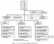
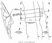
- Figure 1, STS 51-L Salvage Operation Organization, shows the command organization relationships and primary employment of assets.
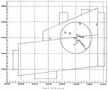
A. Initial Search Area
The initial search area established by SUPSALV was a parallelogram measuring 10 by 25 nautical miles as shown in Figure 2. This area was chosen to be 5 nautical miles on each side of the azimuth along which initial radar tracking analysis showed to be the major STS 51-L debris impact points. The water depths in the search area ranged from 70 feet of sea water (fsw) to approximately 1,200 fsw. This initial search area was west of the main axis of the Gulf Stream but still within the outermost boundaries of the stream. Gulf Stream currents were a significant handicap in conducting search operations.
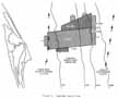
B. Expanded Search Area
The initial search area was incrementally enlarged as the optical and radar data was refined and sonar contacts were classified by divers, ROV's, and manned submersibles. A right Solid Rocket Booster (SRB) debris field was found north of the initial search area and a debris field containing portions of the left SRB was located just inside the eastern edge of the initial search area. Further analysis of trajectory information and the location of both SRB debris fields led to the expansion of the initial search area (Area A) to approximately 420 square nautical miles by adding Search Area B (reference Figure 3). As the search progressed, other areas of STS 51-L debris and potential areas for debris were identified and expanded the search area to 480 square nautical miles. The NR-1 conducted a large area search (3 x 20 nm) east of Area A. No SRB debris was identified in this area and, therefore, provided high confidence that the original search area's eastern border bounded all SRB debris.
C. Search Area Contact Summary and Location of Major STS 51-L Mission Sections
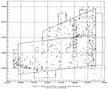
Through May 1, 1986, a total of 691 contacts were identified using the side scanning sonars. The search effort in the bounded area, as shown in Figure 3, Expanded Search Area; is complete. The right and left SRB debris fields are located, as shown, on.....
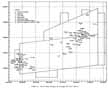
[O215] ...the eastern end of the search area. Figure 4, Search Area Display Contacts Identified During STS 51-L Search Operations, shows the location of all sonar contacts. Many of the contact locations defined debris fields which contained more that one and, in a few cases, up to 500 individual pieces of debris. Each debris field was assigned one contact number and all pieces in a field were listed and tracked under that contact number for management purposes.
D. Remarks on Search Operations
1. Accuracy of Sonar Located Contacts.
The actual location of the contacts identified during side scanning search operations proved accurate to within +/- 35 meters in shallow water depths and + 100 meters in deeper water depths. These location inaccuracies can be attributed to a combination of errors induced by:
(a) Navigational systems.
(b) Vortex shedding due to cross currents in the water column (stronger in deeper depths) resulting in transverse instability of the towed sonar "fish".
(c) Small variations in towing ship course, speed and ship motion (pitch and roll) due to winds and sea state, resulting in tow cable variations and additional sonar "fish" relative position errors.
These contact location inaccuracies were acceptable, as they were within the capabilities of ROV and manned submersible sonars and divers to relocate.
2. Side Scanning Sonar Remarks
(a) The tow speed of the side scanning sonar is important. If the speed is too slow, it will "slur" the trace and, if the speed is too fast, it may not adequately map ("paint") the contacts. Tow speeds of 2-4 knots are normal for side scanning sonar operations and this speed range proved acceptable for this operation as well. This speed is calculated with respect to the bottom (i.e., speed over ground or SOG) and not the ship's speed through the water. Therefore, a ship towing at 4 knots into a 2-knot current would only make 2 knots SOG.
(b) The stability of the towed sonar cylindrical tube, or "fish", is dependent upon its relative speed through the water, motion stability of the tow vessel, and cross currents. A higher relative speed and, therefore, more stability, is obtained by towing the "fish" into the current. Given the high Gulf Stream currents in this search area, it was necessary to tow into the current (i.e., ship heading south) most of the time. Motion stability (course, speed, pitch, and roll) of the tow vessel also affects the stability of the tow "fish." The more constant the motion stability of the vessel, the more stable the "fish" in both depth and transverse accuracy.
(c) Since a 165-meter (122 percent) overlap of bottom area coverage was used and the combined maximum sonar search transverse errors (detailed previously in paragraph III.D. I ) were estimated to be a maximum of 100 meters, there is a high confidence that the search area bottom was fully covered. Detailed evaluation and comparison of adjacent search line bottom area coverage sonar traces also verified full coverage was obtained (i.e., the same contacts appeared in the overlap area of adjacent traces).
IV. CONTACT CLASSIFICATION RESULTS
A. Introduction
Contact classification operations involved the collection of supporting evidence and documentation to determine the identity of contacts located during search operations. Supporting evidence and documentation for contact classification included: still photography, video tapes, manned submersible operator descriptions, diver descriptions, and the recovery of small pieces of debris if they appeared to be STS 51-L related and did not require special handling. NASA and SUPSALV personnel reviewed and evaluated the photographs, video tapes, diver reports, and associated recovered small items of debris to positively classify contacts. Three major classification categories were used: STS 51-L, Non-STS 51-L, and Unconfirmed. Contacts classified as STS 51-L debris were further assigned to one of the following major system categories: Orbiter (including Payload), Left SRB, Right SRB, External Tank, or to Shuttle if it could not be positively linked to one of the other categories.
B. NASA Priority Assignments for Recovery
Contacts classified as STS 51-L debris were prioritized by NASA to determine the order of recovery. Priorities were established based on (1) importance of object recovery relative to determining cause of mishap, and (2) humanitarian considerations. During the course of the salvage effort, established priorities were continually reviewed and revised as additional data and information concerning the sonar contacts was compiled. Daily meetings were convened between NASA, SUPSALV, DDMS, and ESMC to review STS 51-L Salvage Operations progress, redefine priorities, determine the specific employment of assets, and resolve technical problems associated with the recovery process.
C. Summary of Classification Efforts
Of the 691 contacts located during search operations through May 1, 1986, 490 contacts have been classified, 82 of which were classified as STS 51-L debris. Table 2, Summary of Contacts Classified STS 51-L Debris, provides a summary of pertinent classification information. Figure 5, Search Area Display of Contacts Classified STS 51-L Debris, shows the general location of contacts from Table 2. Note that in may cases (reference Table 2), a contact defines a field (area) of contacts versus just a single contact. This tracking method was used in order to reduce the monitoring of contacts to a manageable level. All contacts within a given field were normally investigated during classification operations.
D. Remarks on Classification Operations
1. Bottom Topography
Bottom topography within the search areas was a major factor with respect to the classification of contacts. Much of the actual STS 51-L debris consisted of small pieces (e.g., 1 ft. x 1 ft. and smaller); therefore, small local natural topographic features were the primary cause for the classification of Non-STS 51-L contacts. These contacts included: conch and clam shells, fish bed holes and mounds, coral heads, and small ridges. Shells were a problem in water depths of 60 to 200 feet. Fish beds were identified in water depths of 400 to 800 feet. Coral heads were located over small areas in water depths of 60 to 200 feet. Two ridge lines were identified, both of which run in a nearly north-south direction. One ridge line is located four miles from the eastern edge of search area A in approximately 1,000 feet of water. The other ridge line is located in the east central region of search areas A and B in 400 to 600 feet of water.
2. Discarded Equipment
The search area lies directly over a major merchant shipping lane and vessels navigating the area have occasionally dumped items of equipment into the ocean. Many contacts were, therefore, randomly scattered items of equipment such as 55-gallon drums, coils of wire, refrigerators, etc.
3. Aerospace Debris
Many launches have been initiated from Cape Canaveral Air Force Station (CCAFS) over the last forty (40) years. Debris from some of these flights lies randomly within the search area.
4. Miscellaneous Contacts
Other contacts which were classified as Non-STS 51-L debris include planes, shipwrecks, etc.
5. General Comments
Progress in the classification of STS 51 -L contacts for recovery was tedious and slow. This was due primarily to the large number of contacts involved and the high number of possibilities that existed within the search area for Non-STS 51-L contacts. Of the 490 contacts classified, 408 contacts were Non-STS 51-L, and 82 contacts were STS 51-L related. (1 in 5).
A. Introduction
Contacts classified as STS 51-L debris was prioritized by NASA for order of recovery. Procedures for establishing priorities for recovery and coordinating asset utilization were conducted in the same manner as previously addressed in Section IV.B. For major STS 51-L debris components requiring special recovery techniques, handling, and/or topside post-recovery preparations, specific salvage plans were developed. A list of salvage plans is provided as Table 3, Salvage Plans for STS 51-L Components.
Upon completion of recovery, debris was transported from the Naval Ordinance Test Unit (NOTU) through Cape Canaveral Air Force Station (CCAFS) to Kennedy Space Center (KSC) for analysis and evaluation by the NASA Reconstruction Teams and National Transportation Safety Board (NTSB) members.
B. Summary of STS 51-L Underwater Recovery Operations
A total of 62 individual STS 51-L objects or groups of objects were recovered from the ocean floor through May 1, 1986, 34 of which were SRB debris. Table 4, Summary of Underwater STS 51-L Contacts Recovered, is provided as a listing of recovered STS 51-L debris. Figure 6, Search Area Display of Salvaged STS 51-L Debris, provides the general location of recovered contacts.
C. Remarks on Recovery Operations
1. Divers
Divers were used extensively for recovery operations in shallow water area, (70-300 feet). Surface-supplied air, surface-supplied mixed gas (helium/oxygen), and scuba diving were conducted. Divers proved to be effective for the recovery of debris in shallow areas, where low ocean bottom visibility often imposes an operational limitation on the use of ROV's. The ability of divers to "work by feel" also proved advantageous for the recovery of items in the shallow areas where visibility was frequently less than one foot.
2. Remotely Operated Vehicles (ROV's)
Strong currents throughout the water column and occasional poor visibility limited the use of the Deep Drone. The Deep Drone was an effective asset when current conditions and visibility allowed employment. The Gemini proved to be very effective working in deeper depths and higher currents. Gemini utilized a two-cable configuration with a heavy depressor/tether winch module (TMS). The TMS was lowered to operating depth and provided additional weight to stabilize the main umbilical below the support ship. It decoupled the vehicle from umbilical drag and motion. The work vehicle was then free to maneuver via a 500-foot vehicle tether. The SCORPI was an efficient vehicle for classifying contacts in shallow water areas.
3. Manned Submersibles
Manned submersibles, which are not tethered, operate independent of the surface support ship and are very effective for operating on the bottom. These vehicles were most effective in the classification of contacts in the high surface current areas. Manned submersibles, however, are limited to operational periods of 6 to 8 hours/day. Furthermore, manned submersibles do not have sufficient power to lift heavy objects nor can they be easily used to attach lift lines since there is a possibility of entanglement, thus endangering the crew.
4. NR-1
This research submarine proved to be a very effective and efficient asset. The NR-1 operated during the most severe environmental conditions, stayed submerged for extended durations, and conducted wide area searches. The use of this asset resulted in the location and classification of many contacts in a relatively short period of time so that recovery efforts progressed more effectively.
5. Effects of Environment
Environmental factors were the major obstacles during this salvage operation. Weather systems resulting in high sea states and water turbidity contributed to lost time due to inability to launch and retrieve assets and loss of underwater visibility. The effects of currents at all locations in the water column severely hindered the operations of the divers, ROV's, manned submersibles, and side scanning sonar. Silt buildup, as much as two feet in some areas, severely reduced the ability to locate and recover debris. Because of these environmental conditions, a large number of assets were employed, thereby avoiding extension of the operation over a longer time period.
6. Random Scatter of Components
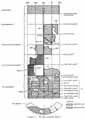
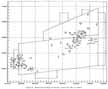
During most salvage operations, the location of the various debris components involved becomes clearer as contacts are located, classified, and recovered. Due to the nature of this mishap, the location of debris components which were classified and recovered was random. Structurally adjacent components of the right SRB were found separated by as much as five miles. Figure 7 shows the locations of recovered right SRB debris. The associated numbers show the assigned salvage contact number for each recovered piece of debris. Figure 8 illustrates the magnitude of the scatter problem.
7. Position Accuracy of Recovered Components
The position accuracy of recovered components was dependent upon the navigational accuracy of the recovery ship and the relative position accuracy of the component with respect to the ship. The primary navigation system used by ships conducting recovery operations was GPS/LORAN-C. The accuracy of GPS/LORAN-C was 10 to 25 meters, dependent upon whether fixes were based on satellite signals or compared/corrected LORAN-C signals. The relative position of the component with respect to the recovery ship was determined by several methods. Methods included the use of: pingers placed on the contact to determine relative position, ROV or manned submersible-to-ship relative positioning systems, and direct ship-to-component wire cable(s). Dependent upon the method used and the water depth, the ship-to-component relative position accuracy ranged from 10 to 25 meters. Recorded component position accuracy ranged from +/-35 meters in shallow water and +/- 50 meters in deep water.
The proper employment, utilization, and coordination of available assets was essential to the successful salvage of STS 51-L debris. Concurrent search, identification, and recovery operations usually involved the use of several assets to affect recovery of a single object. A good example is Contact #131 which is the right SRB aft center segment containing the tang portion of the suspect joint burn through area. This contact was initially located on March I, 1986, by the M/V Liberty Star using side scanning sonar in 560 feet of water. NR-1 operated at the site of Contact #131 on April 5, 1986, classified the item as possible STS 51-L debris, and video taped the contact. After review of the NR-1 video tape, the manned submersible, Sea Link I, operating from the R/V Edwin Link, was assigned to investigate the contact and obtain higher-quality video. On a dive conducted April 12, 1986, the Sea Link I on-board observers verified that Contact #131 was debris from the right SRB and included the tang portion of the joint area in question. Based on the physical size and weight of the debris, the M/V Stena Workhorse was assigned to conduct recovery. Utilizing the ROV Gemini, the M/V Stena Workhorse attached a lift line to the debris and recovered it on April 13, 1986. Therefore, the salvage of this single contact involved three surface vessels, a side scanning sonar, a research submarine, a manned submersible, an ROV, and heavy-lift crane.
The salvage of STS 51-L debris was unique due to the large geographic size (480 square nautical miles) of the search area, the small size of much of the debris being sought, the large number of contacts requiring investigation, and the random dispersion of STS 51-L on the ocean bottom. Environmental conditions within the search area were severe and varied, and often reduced, or even totally curtailed, the operational effectiveness of the STS 51-L salvage operations. These environmental conditions, coupled with the enormity of scope of this operation, necessitated [O221] the simultaneous employment of many different types and numbers of assets. Never before has a massive search and salvage operation of this scope and detail been undertaken. The establishment of a sound organization, strong cooperation within this organization, effective coordination of information and assets, and dedicated personal efforts by both salvage and reconstruction team members, were essential to the success of the STS 51-L Salvage Operation.
|
[O223] Table 3. Salvage Plans for STS 51-L Components (Sheet 2 of 3) | |||
|---|---|---|---|
|
. | |||
|
|
|
|
|
|
. | |||
|
Adden. No. VIII |
C0292 |
Addendum No. VIII (SRB Aft Seg/ET Attach Seg) to Requirements for 51-L SRB Retrieval Operations |
14 MAR 86 |
|
Adden. No. IX |
C0195 |
Addendum No. IX (SRB Case Cylinder Seg) to Requirements for 51-L SRB Retrieval Operations |
14 MAR 86 |
|
Adden. No. X |
C0021 |
Addendum No. X (SRB Aft Seg-Fwd Stiffener) to Requirements for 51-L SRB Retrieval Operations |
22 MAR 86 |
|
Adden. No. XI |
C0021 |
Addendum No. XI (SRB Aft Seg-Stiffener) to Requirements for 51-L SRB Retrieval Operations |
22 MAR 86 |
|
Adden. No. XII |
C0021 |
Addendum No. XII (SRB Aft Seg-Ring) to Requirements for 51-L SRB Retrieval Operations |
22 MAR 86 |
|
Adden. No. XIII |
C0021 |
Addendum No. XIII (SRB Aft SegFragment) to Requirements for 51-L SRB Retrieval Operations |
22 MAR 86 |
|
Adden. No. XIV |
C0502 |
Addendum No. XIV (SRB Cyl SegFld Joint Tang) to Requirements for 51-L SRB Retrieval Operations |
25 MAR 86 |
|
Adden. No. XV |
C0325 |
Addendum No. XV (SRB Case CylClevis Joint) to Requirements for 51-L SRB Retrieval Operations |
25 MAR 86 |
|
Adden. No. XVI |
C0021 (TAR #29-1) |
Addendum No. XVI (SRB Case CylClevis and Tang Joint) to Require meets for 51-L SRB Retrieval Operations |
29 MAR 86 |
|
Adden. No. XVII |
C0214 (TAR #214) |
Addendum No. XVII (SRB Case Segment) to Requirements for 51-L SRB Retrieval Operations |
3 APR 86 |
|
Adden. No.XVIII |
C0615 (TAR#615-1) |
Addendum No. XVIII (SRB Case CylTang) to Requirements for 51-L SRB Retrieval Operations |
4 APR 86 |
|
Adden. No. XIX |
C0615 (TAR#615-2) |
Addendum No. XIX (SRB Case CylClevis) to Requirements for 51-L SRB Retrieval Operations |
4 APR 86 |
|
[O224] Table 3. Salvage Plans for STS 51-L Components (Sheet 3 of 3) | |||
|---|---|---|---|
|
. | |||
|
|
|
|
|
|
. | |||
|
Adden. No. XX |
|
Addendum No. XX (SRB Hardware) to Requirements for 51-L SRB Retrieval Operations |
17 APR 86 |
|
Adden. No. XXI |
C0579 |
Addendum No. XXI (SRB Aft Seg-ET Attach) Requirements for 51-L SRB Retrieval Operations |
4 APR 86 |
|
Adden. No. XXII |
Various (See Note 1) |
Addendum No. XXII (SRB Hardware) to Requirements for 51-L SRB Retrieval Operations |
11 APR 86 |